

Kobold NWS-5225 Installation & Operation Instructions
KOBOLD Instruments, Inc. 1801 Parkway View Drive, Pittsburgh PA 15205
p
Telephone: (412) 788-2830 · FAX: (412) 788-4890 www.koboldusa.com
Specifications
Power Requirements:
Two Wire Switching: 24 to 240 VAC/VDC 50-60 Hz.
Three Wire Switching: 24 VDC
SPDT Relay: 24 VDC or 110 VAC depending
on model number
Solid State Switch Characteristics:
Max. Current: 500 mA.
Min. Current: 7.5 mA.
Leakage Current: 3 mA.
Voltage Drop: 2.5 Volts @ 500 mA.
5.0 Volts @ 20 mA.
10 Volts @ 7.5 mA.
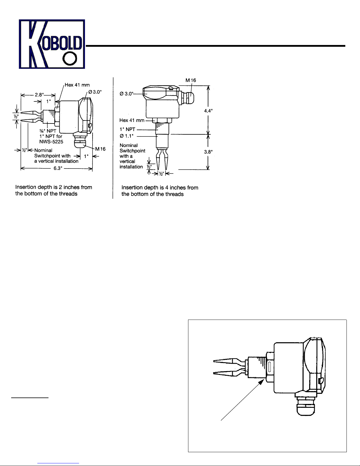
Installation
In order to ensure a leak tight seal, a thread sealant such as
Teflon tape should be used on the probe threads prior to installation.
Series NWS Fork Level switch
Installation/O
Description
KOBOLD’s Series NWS is a compact, vibrating
fork level switch which is suited for use with
non-viscous and viscous liquids as well as
many types of fine granular solids. The switch
employs an forked probe which vibrates at a
resonant frequency. When the probe is
immersed in a medium, the resonant frequency
is dampened. This frequency shift is sensed by
a detecting circuit and results in activation of a
solid state switch or SPDT relay depending on
the model.The Series NWS can be configured
either as a two wire or three wire controller and
is switchable from a normally open to normally
closed (wet-on or dry-on) switch function. Its
solid state design uses no moving parts in the
sensor or switch portions, making the switch
exceptionally reliable.
SPDT Relay Characteristics: 10A @ 110 VAC,
Switching Delay:
Wet to Dry: 500 mSec.
Dry to Wet: 50 mSec.
Fluid Temperature Range: -40 to 270°F
Max. Ambient Temp: 160°F with 200°F Fluid
Max. Operating Pressure: 1000 PSIG @-40 to 120°F
Electrical Protection: NEMA 4/IP 65
Fig. 2: Probe Orientation
eration Instructions
5A resistsive/2A inductive
@ 24 VDC
120°F with 270°F Fluid
760 PSIG @ 120 to 270°F
The NWS should be installed with the cable penetration facing downward. This will
prevent water from settling into the cable gland thereby minimizing leakage into
the electronics. After the unit is installed in its fitting the housing can be roatated to
achieve the proper cable gland orientation
Special Note:
To ensure reliable operation, the series NWS should be
installed in the vessel with the forks of the sensing probe in the
three o’clock and nine o’clock position. The Installation nut on
the NWS has a slotted positioning guide which can be used to
ensure that the probe is installed in the proper position (See
Fig. 2).
The guide slot on the probe installation
nut should be in the 12 O’clock or 6 O’clock
position to ensure that the probe is properly
oriented inside the tank
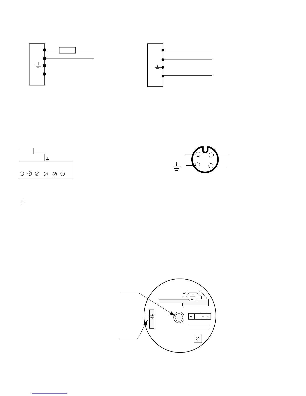
Electrical Connections
Fig. 3 Two Wire Connection
1
+VE
-VE
A
2
3
4
Load
24-240 VAC/VDC
Neut.
Line
The two wire connection switches line
voltage to the load device when switch
is activated. The load device is connected
in series with the NWS.
Fig. 5 Wiring for Relay Output ( R01 & R03)
V-
NC
C
NO
V+
Fig. 4 Three Wire Connection
+VE
-VE
1
A
2
3
4
Output
+
24 VDC In
-
The three wire configuration switches
24 VDC to the output when the NWS is
activated
Fig. 6 Plug Connector Pinout (option -M12) 24 VDC only
+VE
1
2
4
3
A
-VE
NO = Normally Open Contact
NC = Normally Closed Contact
= Safety Ground
V+
= Power, 110 VAC or 24 VDC
V-
depending on model
Operation
Status Indicator
Flashing: Switch not activated (open switch)
Steady: Switch activated (closed switch)
Logic Selector Switch
for normally open or
normally closed operation
Color Codes on Mating Connector
White = 1 = A
Blue = 2 = +VE
Black = 3 = Ground
Brown = 4 = -VE
LOAD/CHARGE/LAST
AC/DC 24-240 V
DRY-ON
VIOE
LEER
WET-ON
PLEIN
VOLL
-VE
+VE A
4
213
Rev. 10/05/01
 Loading...