

Warranty Service and Repair
If for some reason your product must be returned for factory service,
contact your Kobold distributor to receive a material return authorization number first, and provide them with the following information:
KOBOLD
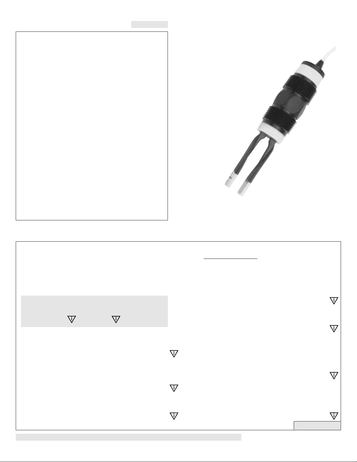
Tuning Fork Sensor
1. Part number, serial number
2. Name and telephone number of a person who can answer
questions related to the product and its application
3. Return shipping address
4. Brief description of the symptom
5. Brief description of the application
Once you have received a return authorization form, ship the product
prepaid in its original packing to:
KOBOLD Instruments Inc.
1801 Parkway View Drive
Pittsburgh, PA 15205
Please include any related symptom and application information with
your product. This information enables our service technicians to
process your repair order as quickly as possible.
NWP-1405 Series
Owner’s Manual
Version 2.1
12/2013, All rights reserved.
Part # NWP_1405_Manual
WARNING
Compass Corrosion Guide, available
damage or break the sensor and void the warranty.
Do not squeeze the forks together. Doing so could
ment and control points, each having a different sensing technology.
sive applications. In hazardous applications, use redundant measureThe NWP series sensor should not be used within flammable or explo-
Flammable, Explosive and Hazardous Applications:
codes.
be performed in accordance with all applicable national, state, and local
exceed a maximum of 36 volts DC. Electrical wiring of the sensor should
The supply voltage used to power the NWP series sensor should never
Wiring and Electrical:
1.667 psi per °C. above 25 °C.
up to 90 °C, and for use at pressures up to 150 psi @ 25 °C., derated @
The NWP series sensor is designed for use in application temperatures
Temperature and Pressure:
from Compass Publications (619-589-9636).
its application liquids, refer to the
liquids. To determine the chemical compatibility between the sensor and
the model which you have selected is compatible with the application
with the forks made of PPS (40% glass filled). Make sure that
body of the model NWP-1405 is made of PP (Polypropylene)
The NWP series sensor is available in one wetted material version. The
Material Compatibility:
check for leaks prior to system start-up.
within the fitting, beyond a maximum of 80 inch-pounds torque. Always
Use a proper sealant with all installations. Never overtighten the sensor
Proper Installation and Handling:
result in property damage or serious injury.
installed system, and maintain all components. The failure to do so could
is appropriate for the application, install it properly, perform tests of the
of applications, it is the user's responsibility to select a sensor model that
gies. While each of these sensors is designed to operate in a wide variety
Kobold manufactures a wide range of liquid level sensors and technolo-
User's Responsibility for Safety:
the exact model which you have purchased.
series. Please refer to the part number located on the sensor label to verify
different models of Tuning Fork sensors from Kobold, all in the NWP
OR USING THIS PRODUCT. This manual includes information on two
PLEASE READ THE ENTIRE MANUAL PRIOR TO INSTALLING
About this Manual:
Step One
SAFETY PRECAUTIONS
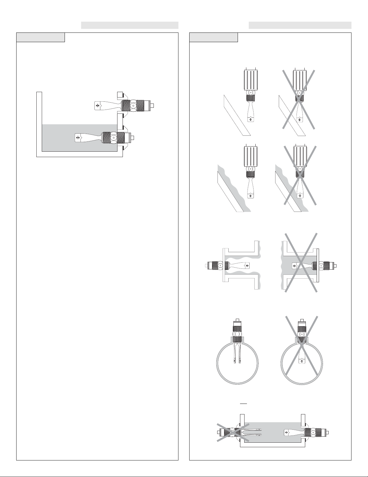
ORIENTATIONINSTALLATION
Step Two
Through Wall Installation:
Kobold’s NWP series sensors may be installed through the top, side or
bottom of a tank wall. The sensor has male 3/4" NPT threads on either side
of a 15/16" wrench flat. This enables the user to select the sensor’s mounting
orientation, installed outside of the tank in, or inside of the tank out.
Step Three
When installing the NWP, make sure that the forks do not touch the walls
of the tank. Consider possible build up along the inner tank wall.
Higher viscosity liquids may build up inside of a flange and cause the
NWP to fail wet.
Side View
If installing the tuning fork within a pipe, make sure the forks allow the
liquid to flow between them and not around them.
When installing the NWP horizontally, make sure that the forks orientation is vertical and not horizontal.
Side View
Side ViewSide View
Step Four Step Five
WIRING WIRING
[Dry Condition]
Sensor
(NO)
RED
GRN
SHLD
WHT
BLK
LOAD
LOAD
OR
[+]
[-]
[Dry Condition]
Sensor
(NC)
BLK
GRN
SHLD
WHT
RED
LOAD
LOAD
OR
[+]
[-]
[Dry Condition]
Sensor
(NO)
RED
GRN
SHLD
WHT
BLK
LOAD
[AC Power]
[+]
[-]
[Dry Condition]
Sensor
(NC)
BLK
GRN
SHLD
WHT
RED
LOAD
[AC Power]
[+]
[-]
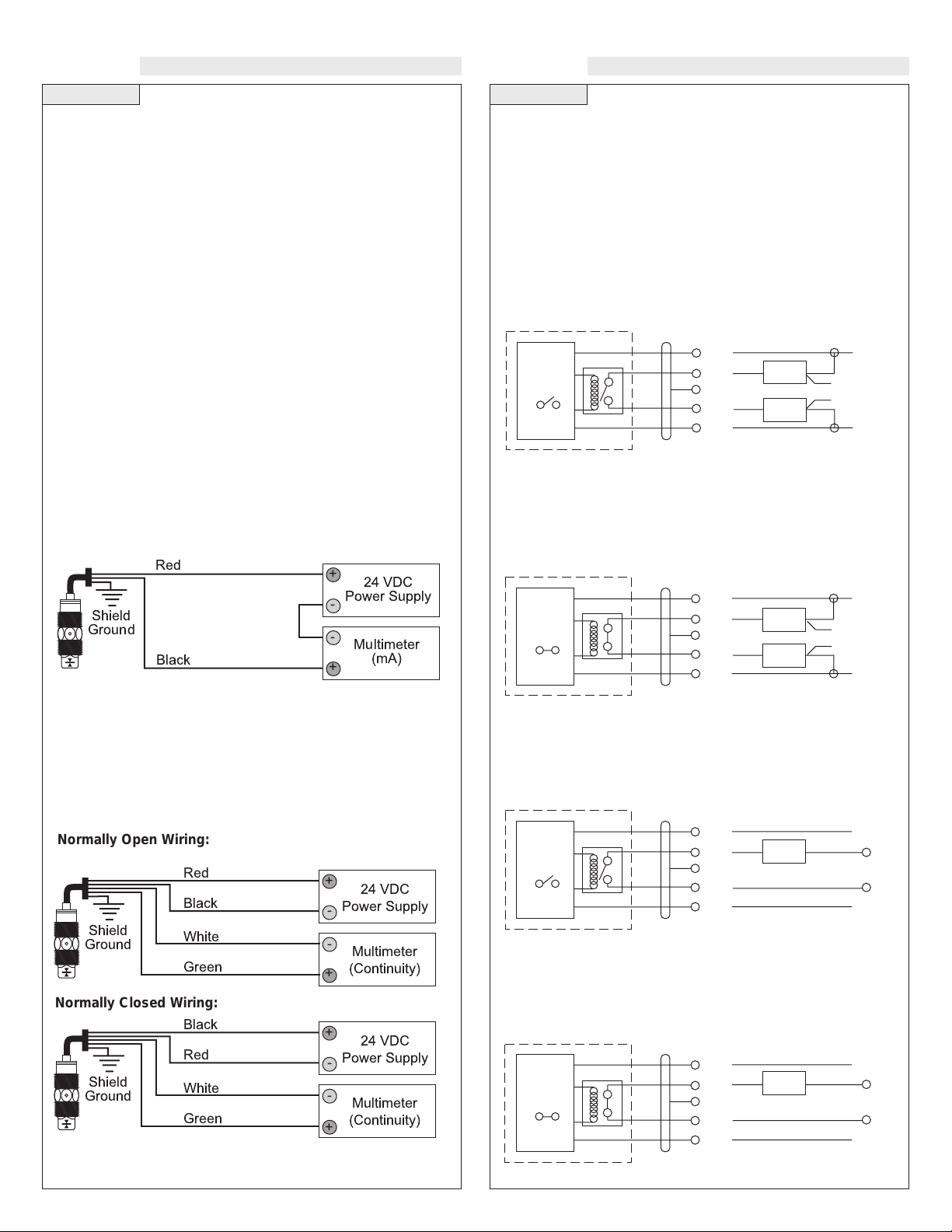
Wiring the Relay Output:
The NWP-1405 relay output can be wired as a dry contact to a
VDC or VAC power source. The NWP-1405 does require 12 - 36 VDC
power to operate the sensor and switch the relay. All illustrations
below identify a dry switch state as the normal position of the relay.
Switching a Normally Open DC Load:
The Red wire connects to Positive (+) of the power supply and the
Black wire connects to Negative (-). The LOAD can be attached to
either the Green or White wires. Complete the circuit by either connecting the Green to (+) VDC power or White to (-) VDC power (see
illustration below).
Switching a Normally Closed DC Load:
The Black wire connects to Positive (+) of the power supply and the
Red wire connects to Negative (-). The LOAD can be attached to
either the Green or White wires. Complete the circuit by either connecting the Green to (+) VDC power or White to (-) VDC power (see
illustration below).
Switching a Normally Open AC Load:
The Red wire connects to Positive (+) of the DC power supply and the
Black wire connects to Negative (-). The LOAD can be attached to
the Green wire and the Hot of the VAC power. Connect the White to
the Neutral of the VAC power (see illustration below).
Switching a Normally Closed AC Load:
The Black wire connects to Positive (+) of the DC power supply and
the Red wire connects to Negative (-). The LOAD can be attached to
the Green wire and the Hot of the VAC power. Connect the White to
the Neutral of the VAC power (see illustration below).
Supply Voltage:
The supply voltage to the NWP-1405 level switch should never
exceed a maximum of 36 VDC.
Alternative controllers and power supplies, with a minimum output
of 12 VDC up to a maximum output of 36 VDC, may also be used with
the NWP-1405 level switch.
Required Cable Length:
Determine the length of cable required between the NWP-1405
level switch and its point of termination. Allow enough slack to
ensure the easy installation, removal and/or maintenance of the sensor. The cable length may be extended up to a maximum of 1000 feet,
using a well-insulated, 14 to 20 gauge shielded four conductor cable.
Wire Stripping:
Using a 10 gauge wire stripper, carefully remove the outer layer of
insulation from the last 1-1/4" of the sensor's cable. Unwrap and discard the exposed foil shield from around the signal wires, leaving the
drain wire attached if desired. With a 20 gauge wire stripper, remove
the last 1/4" of the colored insulation from the signal wires.
Signal Outputs (Current sensing):
This method, when used with an appropriate controller, uses only
two wires (Red and Black). The sensor draws 5 mAwhen it is dry,
and 19 mA when wet. NC/NO status must be set by the controller. The
White and Green wires are not used.
Signal Output (Relay switching):
Allows the sensor to switch a small load on or off directly, using an
internal 1Arelay (60 VAC/60 VDC). The NWP-1405 level switch
relay utilizes 4 wires (red, black, white and green) and a bare shield
wire. The NO/NC status is set by the polarity of the voltage feeding
the red and black wires. The green wire is the common for the relay
and the white wire is the NO or NC, depending on the polarity of red
and black.
Red
Black
Shield
Ground
24 VDC
Power Supply
+
-
Multimeter
(Continuity)
-
+
White
Green
Red
Black
Shield
Ground
24 VDC
Power Supply
+
-
Multimeter
(mA)
-
+
Normally Open Wiring:
Black
Red
Shield
Ground
24 VDC
Power Supply
+
-
White
Green
Multimeter
(Continuity)
-
+
Normally Closed Wiring:
Step Seven
MAINTENANCE
General:
The NWP-1405 level switch requires no periodic maintenance
except cleaning as required. It is the responsibility of the user to
determine the appropriate maintenance schedule, based on the specific characteristics of the application liquids.
Cleaning Procedure:
1. Power: Make Sure that all power to the sensor, controller and/or
power supply is completely disconnected.
2. Sensor Removal: In all through-wall installations, make sure
that the tank is drained well below the sensor prior to removal.
Carefully, remove the sensor from the installation.
3.
4. Sensor Installation: Follow the appropriate steps of installa-
tion as outlined in the installation section of this manual.
Testing the installation:
1. Power: Turn on power to the controller and/or power supply.
2. Immersing the switch: Immerse the sensing tip in its applica-
tion liquid, by filling the tank up to the switches point of actuation. An alternate method of immersing the switch during preliminary testing is to hold a cup filled with application liquid up to
the switch's tip.
3. Test: With the switch being fluctuated between wet and dry
states, the switch indicator light in the controller should turn on
and off. If the controller doesn't have an input indicator, use a voltmeter or ammeter to ensure that the switch produces the correct
signal.
4. Point of actuation: Observe the point at which the rising or
falling fluid level causes the switch to change state, and adjust the
installation of the switch if necessary.
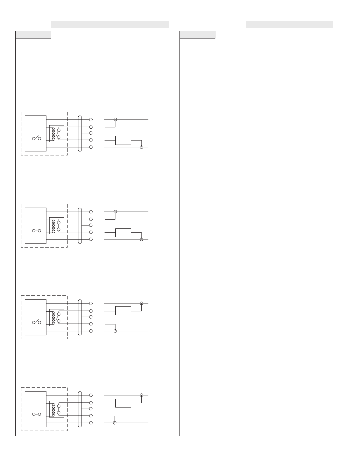
Step Six
WIRING
Wiring as a P-Channel or N-Channel output:
The NWP-1405 can be substituted for either a P-Channel (PNP,
sourcing) output or a N-Channel (NPN, sinking) output.
Normally Open DC Load as a P-Channel Output:
To wire as a N/O P-Channel output, follow the directions below. The
Red wire connects to Positive (+) of the power supply and the Black
wire connects to Negative (-). The Green wire is jumpered to the Red
wire while the White wire is connected to the LOAD. Jumper the
LOAD back to the Negative (-) to complete the circuit.
[Dry Condition]
Sensor
(NO)
RED
GRN
SHLD
WHT
BLK
LOAD
[+]
[-]
[Dry Condition]
Sensor
(NC)
BLK
GRN
SHLD
WHT
RED
LOAD
[+]
[-]
[Dry Condition]
Sensor
(NO)
RED
GRN
SHLD
WHT
BLK
LOAD
[+]
[-]
[Dry Condition]
Sensor
(NC)
BLK
GRN
SHLD
WHT
RED
LOAD
[+]
[-]
Normally Closed DC Load as a N-Channel Output:
To wire as a NC N-Channel output, follow the directions below. The
Black wire connects to Positive (+) of the power supply and the Red
wire connects to Negative (-). The White wire is jumpered to the Red
wire while the White wire is connected to the LOAD. Jumper the
LOAD back to the Positive (+) to complete the circuit.
Normally Open DC Load as a N-Channel Output:
To wire as a NO N-Channel output, follow the directions below. The
Red wire connects to Positive (+) of the power supply and the Black
wire connects to Negative (-). The White wire is jumpered to the
Black wire while the Green wire is connected to the LOAD. Jumper
the LOAD back to the Positive (+) to complete the circuit.
Normally Closed DC Load as a P-Channel Output:
To wire as a NC P-Channel output, follow the directions below. The
Black wire connects to Positive (+) of the power supply and the Red
wire connects to Negative (-). The Green wire is jumpered to the
Black wire while the White wire is connected to the LOAD. Jumper
the LOAD back to the Negative (-) to complete the circuit.
Cleaning the Sensor: Use a soft bristle brush and mild deter-
gent, carefully wash the NWP-1405 level switch. Do not use
harsh abrasives such as steel wool or sandpaper, which might
damage the surface sensor. Do not use incompatible solvents
which may damage the sensor's PP, PFA, PVDF or PPS plastic
body.
Operating Pressure (psi)
Sh iel d Ground :
Ba re
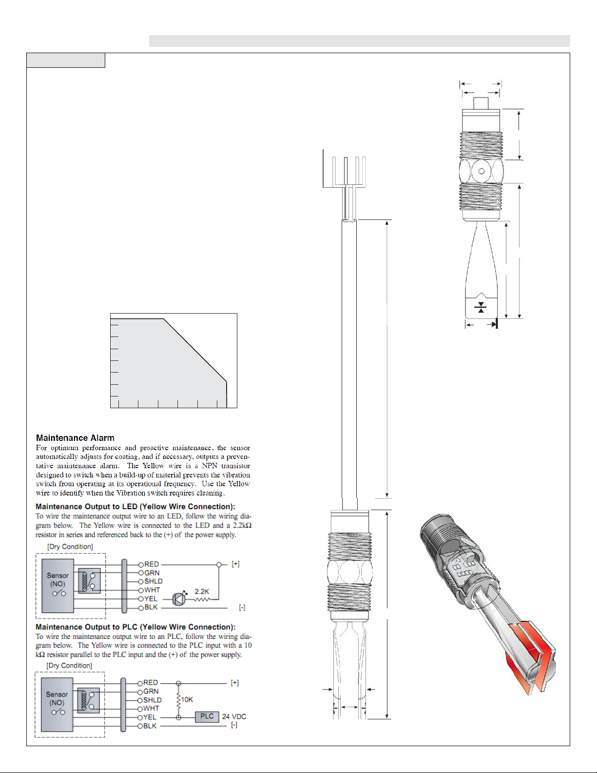
Maintenance : Yellow
Rela y
Outpu t :
White
Re la y C o mmo n :
Green
Po wer : (+) Re d
(- ) B lac k
8' Cable
SPECIFICATIONS
Unacceptable
Range
Acceptable
Range
Step Eight
Accuracy: ± 2 mm in water
Repeatability: ± 1 mm in water
Frequency: 400 Hz (dry)
Supply voltage: 12-36 VDC
Consumption: Dry: 8 mA nominal
Wet: 19 mA nominal
Contact type:
Contact rating:
Contact output:
Temperature range:
Pressure range:
Probe material:
Probe rating:
Mounting threads:
Cable type:
160
140
120
100
80
60
40
20
00
-20 00 20 40 60 80 100
(1) SPST relay
60 VAC/VDC @ 1A max.
Selectable NO/NC states
F: -40° to 194 °
C: -40° to 90°
150 psi @ 25°C., derated @ 1.667
psi per °C. above 25° C.
PP/PPS® (40% glass filled)
NEMA 6 / IP68
3/4" NPT
8 ft., 5-wire, 22 gauge with shield
ground & PP jacket
Temperature / Pressure Derating
Temperature (°C)
Dimensions
1.05"
.88"
1.14"
.55"
2.75"
1.98"
.50"
Technology
The Tuning Fork switch vibrates at a
nominal frequency of 400 Hz. As the
switch becomes immersed in a liquid or
slurry, a corresponding frequency shift
occurs. When the measured frequency
shift reaches an appropriate value, the
switch changes state indicating the
presence of a liquid or slurry medium.
0.35"
4.50"
.72"
.38"
 Loading...