

Kobold NVI Operating Instructions Manual

Operating Instructions
for
Vibrating Level Switches
Model: NVI

NVI
page 2 NVI K04/0517
1. Contents
1. Contents ........................................................................................................ 2
2. Note .............................................................................................................. 3
3. Instrument Inspection .................................................................................... 3
4. Regulation Use .............................................................................................. 3
5. Operating Principle ........................................................................................ 4
6. Mechanical Connection ................................................................................. 4
7. Electrical Connection .................................................................................... 7
7.1 General ................................................................................................ 7
7.2 Operation Diagram .............................................................................. 7
8. Commissioning .............................................................................................. 8
8.1 Density (Sensitivity) Adjustment (Switch A) ......................................... 8
8.2 High/Low Fail-Safe Mode (Switch C) ................................................... 8
8.3 Time Delay (Switch B) ......................................................................... 8
9. Technical Information .................................................................................... 9
10.Derating Diagram ........................................................................................ 10
11.Order Codes ............................................................................................... 10
12.Maintenance ............................................................................................... 10
13.Storage ....................................................................................................... 11
14.Guarantee ................................................................................................... 11
15.Dimensions ................................................................................................. 11
16.EU Declaration of Conformance .................................................................. 12
Manufactured and sold by:
Kobold Messring GmbH
Nordring 22-24
D-65719 Hofheim
Tel.: +49(0)6192-2990
Fax: +49(0)6192-23398
E-Mail: info.de@kobold.com
Internet: www.kobold.com

NVI
NVI K04/0517 page 3
2. Note
Please read these operating instructions before unpacking and putting the unit
into operation. Follow the instructions precisely as described herein.
The devices are only to be used, maintained and serviced by persons familiar
with these operating instructions and in accordance with local regulations
applying to Health & Safety and prevention of accidents.
When used in machines, the measuring unit should be used only when the
machines fulfil the EC-machine guidelines.
3. Instrument Inspection
Instruments are inspected before shipping and sent out in perfect condition.
Should damage to a device be visible, we recommend a thorough inspection of
the delivery packaging. In case of damage, please inform your parcel service /
forwarding agent immediately, since they are responsible for damages during
transit.
Scope of delivery:
The standard delivery includes:
Vibrating Level Switch model NVI
Operating Instructions
4. Regulation Use
Any use of the Vibrating Level Switch, model: NVI, which exceeds the
manufacturers specification may invalidate its warranty. Therefore any resulting
damage is not the responsibility of the manufacturer. The user assumes all risk
for such usage.
NVI
page 4 NVI K04/0517
5. Operating Principle
The KOBOLD NVI level switch is a mechanical system that is made to resonate
by an electronic switching operation. When the probe is covered by a medium,
the vibrations are damped. This change in the resonance frequency is converted
to a switching signal by electronic means.
The combined vibrating switch can be used in powdery media and granular
materials. The medium to be measured should have a density of at least 0.05
kg/dm3. The single rod design prevents deposit formation. The rod is selfcleaning, as the vibrations shake off the medium.
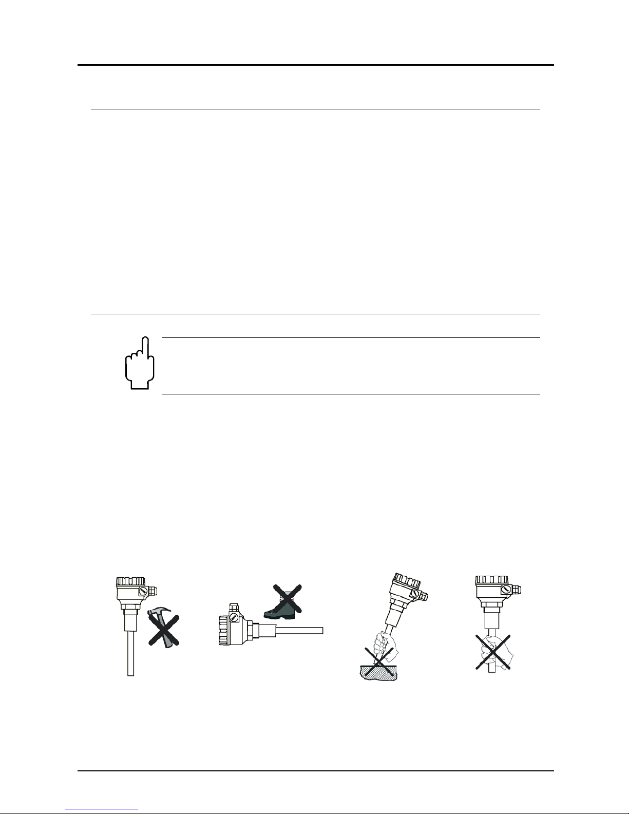
6. Mechanical Connection
Important! Handle the device with great care, especially the sensing
probe. A larger impact on the sensing probe may ruin its resonance
system. Probes exposed to falling material or mechanical loads
should be protected.
Prior to the installation, it is advised to test the switching function of the unit on
a sample quantity of material and to set „Density“ switch according to the
density of medium. (see 8. Commissioning)
Screw in the device by its hexagon neck. After screwing tight the process
connection, the housing can be rotated (max. 300 °), to adjust the cable glands
to the required position. In some cases such as material caving or arching you
will need to mount the vibration rod at a clearance from the desired limit.
The model NVI is not suggested to be used for low level detection in high
density materials.
Max. switching Min. switching
 Loading...