

Page 1
Operating Instructions
for
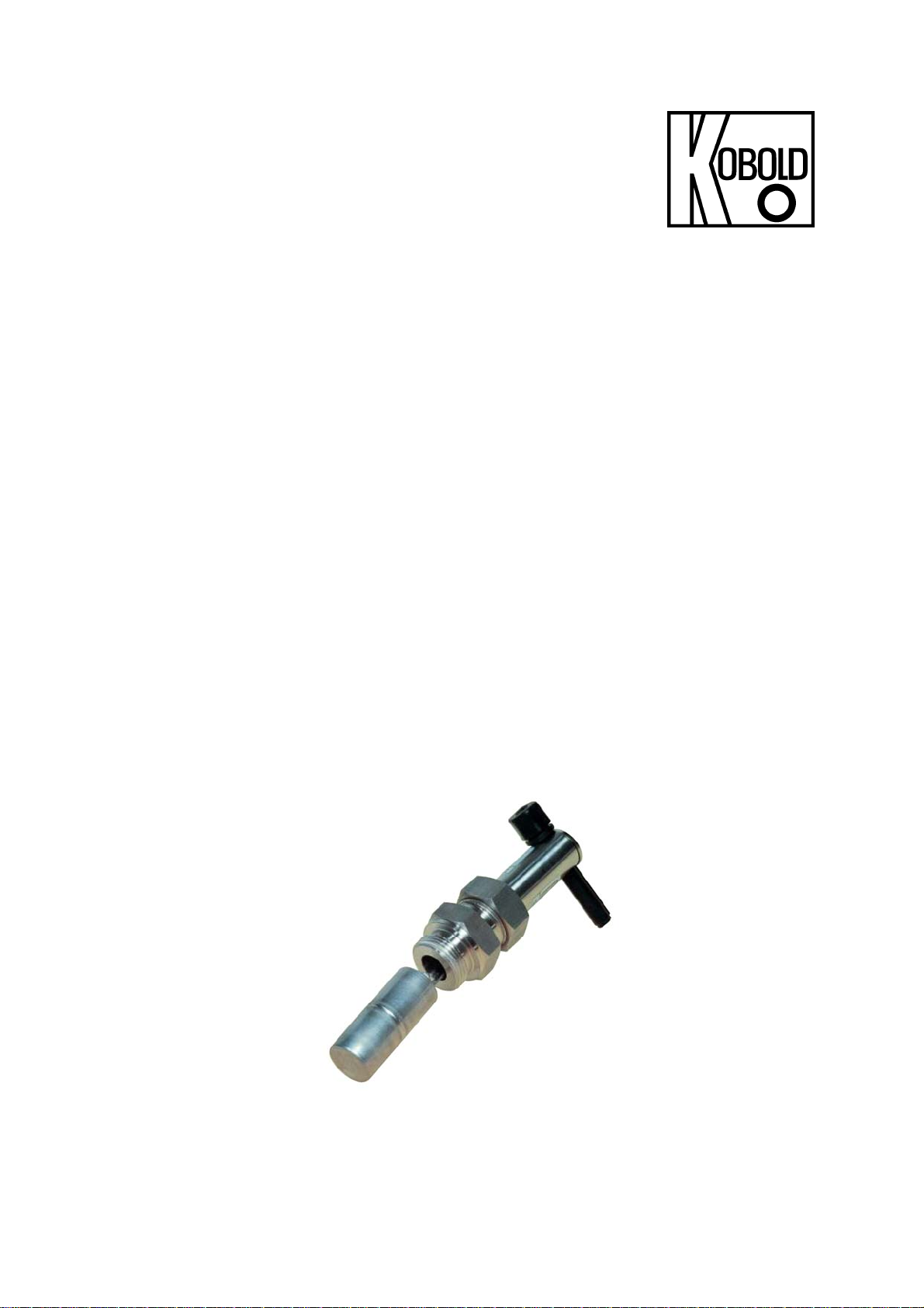
Level Switches
Model: NV
Page 2

NV
1. Contents
1. Contents ............................................................................. 2
2. Note .................................................................................... 3
3. Instrument Inspection ......................................................... 3
4. Regulation Use ................................................................... 3
5. Operating Principle ............................................................. 4
6. Mechanical Connection ...................................................... 4
7. Electrical Connection .......................................................... 5
8. Commissioning ................................................................... 5
9. Maintenance ....................................................................... 5
10. Technical Information ......................................................... 6
11. Order Codes ....................................................................... 7
12. Dimensions ......................................................................... 7
13. EU Declaration of Conformance ......................................... 8
Manufactured and Marketed by:
Kobold Messring GmbH
Nordring 22-24
D-65719 Hofheim
Tel.: +49 (0)6192-2990
Fax: +49(0)6192-23398
E-Mail: info.de@kobold.com
Internet: www.kobold.com
Page 2 NV K08/0917
Page 3

NV
2. Note
Please read these operating instructions before unpacking and putting the unit
into operation. Follow the instructions precisely as described herein.
The devices are only to be used, maintained and serviced by persons familiar
with these operating instructions and in accordance with local regulations
applying to Health & Safety and prevention of accidents.
When used in machines, the measuring unit should be used only when the
machines fulfil the EC-machine guidelines.
3. Instrument Inspection
Instruments are inspected before shipping and sent out in perfect condition.
Should damage to a device be visible, we recommend a thorough inspection of
the delivery packaging. In case of damage, please inform your parcel service /
forwarding agent immediately, since they are responsible for damages during
transit.
Scope of delivery:
The standard delivery includes:
Level Switch model: NV
Operating Instructions
4. Regulation Use
Any use of the Level Switch, model: NV, which exceeds the manufacturer’s
specification may invalidate its warranty. Therefore, any resulting damage is not
the responsibility of the manufacturer. The user assumes all risk for such usage.
The units of type NV are intended to be used for monitoring of liquid-level
measurement. Only use liquids which are chemically inert to the materials used in
the construction of these devices.
By using at least two level monitors, where one is used for minimum level and the
other for max. level, liquid level control may be accomplished.
NV K08/0917 Page 3
Page 4

NV
5. Operating Principle
The Kobold Level Switch model NV is a reasonably-priced compact instrument
for monitoring levels. A stainless steel cylindrical float attached to one end of a
balance arm moves up and down with the liquid level.
The motion of the float is transferred to a permanent magnet fitted at the other
end of the balance arm. The permanent magnet switches a reed contact that is
fitted in a sliding tube outside the medium. The tube is set as a N/O contact at the
factory, that is, the contact closes when the level rises. The switching function is
reversed by moving the tube. The instruments are delivered in standard sleeves
for side installation. PTFE tape is used to seal the switch.
6. Mechanical Connection
The float switch is to be attached in such a way that the float can move freely
over its entire range and must not come in contact with the walls, bottom, or
cover of the container. Positions, where turbulence may be encountered, due to
agitators or intake valves, are unsuitable for proper operation.
The container should not have freely moving solids or ferrite particles, since these
will deposit on float magnet- resulting in disturbance in switching process. If the
liquid contains sediments or suspended materials, special care must be exercised
in order to keep these materials away from the float system.
The switch should be attached to the system while keeping in mind the need for
easy access for installation and maintenance.
Ensure that the permitted max. operational pressure and temperature limits
are not exceeded.
Make sure that no remains of packing material exist inside the unit.
The installation position must be horizontal.
If possible, examine all the connection joints for proper sealing, just after
mechanical installation.
Page 4 NV K08/0917
Page 5

NV
7. Electrical Connection
Make sure that the electric supply lines are not active.
Connect the cable with your power supply.
The contact box is made of fibreglass reinforced plastic. This material provides
protective insulation according to VDI 0720 class II; a separate protection
conductor is not required.
Connection scheme
After connections are made to the desired external devices, the unit is ready for
operation.
8. Commissioning
Readjustment of switching unit
For the adjustment of switching unit, the locking disk on the upper part of housing
must be loosened and the switching unit repositioned. To assist the adjustment
procedure, a blue (white) or red arrow is provided on the switching unit. The
leading edge of locking disk serves as adjustment mark.
N.O. contact:
The switching unit is to be set within the range of red arrow.
The contact closes on increasing liquid-level.
N.C. contact:
The switching unit is to be set within the range of blue (white) arrow.
The contact opens on increasing liquid-level.
9. Maintenance
As long as the medium to be measured is not contaminated, the device NV is
maintenance-free. In particular, pay attention to ferrite particles in the medium,
which tend to settle on the magnet, and can lead to problems. Larger dirt particles
can cause seizure of the horizontal beam. Depending upon the degree of
pollution of your medium, we recommend checking the device(s) after regular
intervals.
NV K08/0917 Page 5
Page 6

NV
10. T echnical Information
Housing: NV-11...: brass, Ms 58
NV-12...: stainless steel, 1.4301
Connections: NV-11...: brass, Ms 58
NV-12...: stainless steel, 1.4301
Float: stainless steel, 1.4301
Leaf spring: stainless steel, 1.4310
Balance arm: stainless steel, 1.4310
Sleeve: NV-11...: brass, Ms 58
NV-12...: stainless steel, 1.4301
Contact tube: Polyamide
Seal: NV-11...: NBR
NV-12...: FPM
Max. temperature: 110 °C
Max. pressure: 16 bar
Installation position: horizontal
Bistable reed contact:
R N/O contact / N/C contact standard
max. 2 A, max. 230 V
max. 40 W, 40 VA
U Changeover contact standard
max. 0,5, max. 150 V
max. 20 W, 20 VA
C N/O contact / N/C contact
2 A, 20 V
max. 40 W
D Changeover contact
0.13 A, 150 V
max. 20 W
Elektr. Anschluss: PVC-Kabel
Electrical connection: 1.5 m cable, PVC
Contact resistance: max. 80 mΩ
Closing point: max. 6 mm (above centre line)
Opening point: max. 3 mm (below centre line)
Switching hysteresis: approximately 8 mm
Ex-area: ATEX Zone 1 as “Simple operator”
Density: > 0.8 kg/dm3 ...25 mm float
> 0.7 kg/dm3 ...50 mm float
Protection: IP 65
Average electrical switch contact life (MTTF):
AC/DC
AC/DC
0.18 A, 230 VAC
AC,
0.5 A, 40 VAC
AC,
®
USC
®
USC
at max. electrical load: 105 switching operations
at half load (<10% max. load): 5*107 switching operations
at low load (<10V/<1mA): 108 switching operations
Page 6 NV K08/0917
Page 7

NV
11. Order Codes
Example: NV-1101 R1
Model Material
NV-
11 = brass
12 = st.st.
1)
only for N/O contact “R” and “C”
2)
length as described
3)
only for N/O contact “R”
Connection/
Length of float
01 = G ¾; 25 mm
02 = M27x1.5; 25 mm
03 = G ¾; 50 mm
04 = M27x1.5; 50 mm
Contact type,
R = N/O contact
(Standard CE)
C = N/O contact
(cCSAus)
U = Changeover contact
(Standard CE)
D = Changeover contact
(cCSAus)
Cable type/length
PVC cable
1 =1.5 m (standard)
2 =2.0 m
4 =3.0 m
6 =4.0 m
8 =5.0 m
P = PVC-cable, special length
S = silicone cable
G = yellow PUR cable
1)
1)
1))
1)
2)3)
2)3)
2)
12. Dimensions
min. 63
AF 30
94
155 resp. 130
AF 32
50 or 25
G3/4 or M27x1.5
NV K08/0917 Page 7
Page 8

NV
13. EU Declaration of Conformance
We, KOBOLD Messring GmbH, Hofheim-Ts, Germany, declare under our sole
responsibility that the product:
Level Monitor model: NV...
to which this declaration relates is in conformity with the standards noted below:
EN 61010-1:2011
Safety requirements for electrical equipment for measurement, control and
laboratory use – Part 1: General requirements
EN 60529:2014
Protection through housing (IP-Code)
Also the following EC guidelines are fulfilled:
2014/35/EU Low voltage guidelines
2011/65/EU RoHS
EN 50581:2012 Technical documentation for the assessment of electrical
and electronic products with respect to the restriction of hazardous substances
Hofheim, 12. Sept. 2017
H. Peters M. Wenzel
General Manager Proxy Holder
Page 8 NV K08/0917
 Loading...