

Page 1
Operating Instruction
for
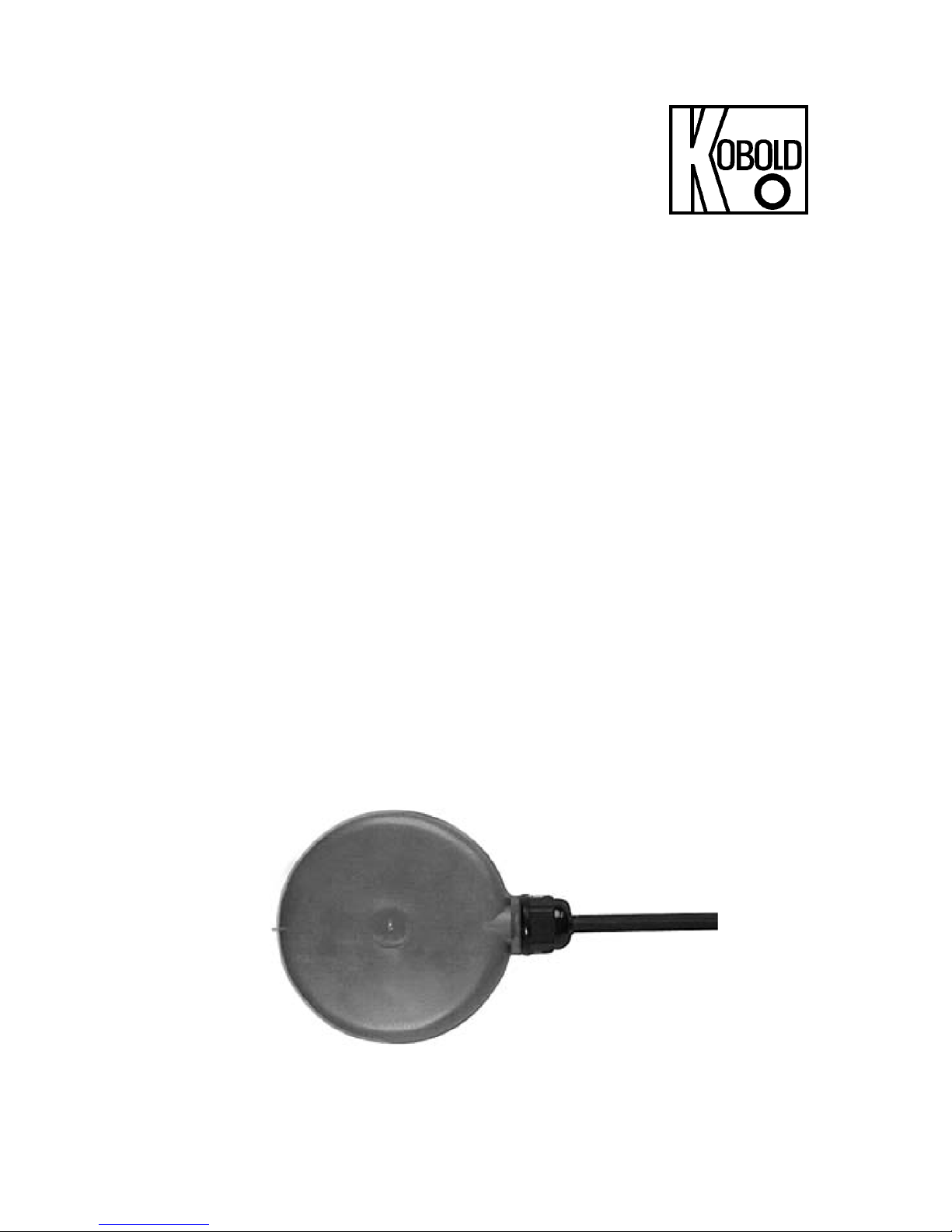
Float Switch
Model: NSM
Page 2

NSM
Page 2 NSM K01/1016
1. Contents
1. Contents ............................................................................. 2
2. Note .................................................................................... 3
3. Instrument Inspection ......................................................... 3
4. Regulation Use ................................................................... 3
5. Operating Principle ............................................................. 4
6. Mechanical Connection ...................................................... 4
7. Electrical Connection .......................................................... 5
8. Maintenance ....................................................................... 5
9. Technical Information ......................................................... 6
10. Order Codes ....................................................................... 6
11. Dimensions ......................................................................... 7
12. EU Declaration of Conformance ......................................... 8
Manufactured and Marketed by:
Kobold Messring GmbH
Nordring 22-24
D-65719 Hofheim
Tel.: 06192-2990
Fax: 06192-23398
Internet: http: //www.kobold.com
e-mail: [email protected]
Page 3

NSM
NSM K01/1016 Page 3
2. Note
Please read these operating instructions before unpacking and putting the unit
into operation. Follow the instructions precisely as described herein.
The devices are only to be used, maintained and serviced by persons familiar
with these operating instructions and in accordance with local regulations
applying to Health & Safety and prevention of accidents.
3. Instrument Inspection
These devices are checked before shipping and sent out in perfect condition.
Should damage to a device be visible, we recommend a thorough inspection of
the delivery packing. In case of damage, please inform your parcel service/
forwarding agent immediately, since they are responsible for damages during
transit.
Scope of delivery:
Standard scope of delivery applies:
Float switch, model: NSM
Operating instruction
4. Regulation Use
These units of type NSM are employed for purposes of monitoring the filling-level
status of liquids. Only such liquids may be measured which are compatible with
the materials used in the construction of these units.
Float switches are usable as switching elements for level control in almost any
situation, where a two-point control is sufficient to solve the problem under
consideration. These devices are easy to install and practically maintenance-free.
Float switches represent an inexpensive solution while offering high reliability at
the same time.
Page 4

NSM
Page 4 NSM K01/1016
5. Operating Principle
The float switch consists of a body with built-in micro-switch. The supplied contact
is a change-over type (SPDT), which can be used selectively as a N.O. or N.C.
contact.
The contact switches when exceeding or falling short of the horizontal float
position. Setting switch point is carried out through on-site assembly of the switch
at the desired position by cable-clamping. When top mounting, the switching point
is determined by means of ballast cable weights.
6. Mechanical Connection
The float switch cable is fastened centrally between the lower and upper levels.
The switching angle of the switch is approx. 45°. Thus the difference in level is
about 1.4 times that of free cable length.
Example: Free cable-length 10 cm
Level difference approx. 14cm
Attention: The bending radius of the cable is 15-times of the cable diameter.
Neoprene cable: approx. 11 cm
The cable should not be bound with strap-hardened cable binder and not in a
vertical direction, if possible. The use of bending protection trumpets is
recommended.
Page 5
NSM
NSM K01/1016 Page 5
7. Electrical Connection
The maximum electrical load of the switch is indicated on the instrument sticker.
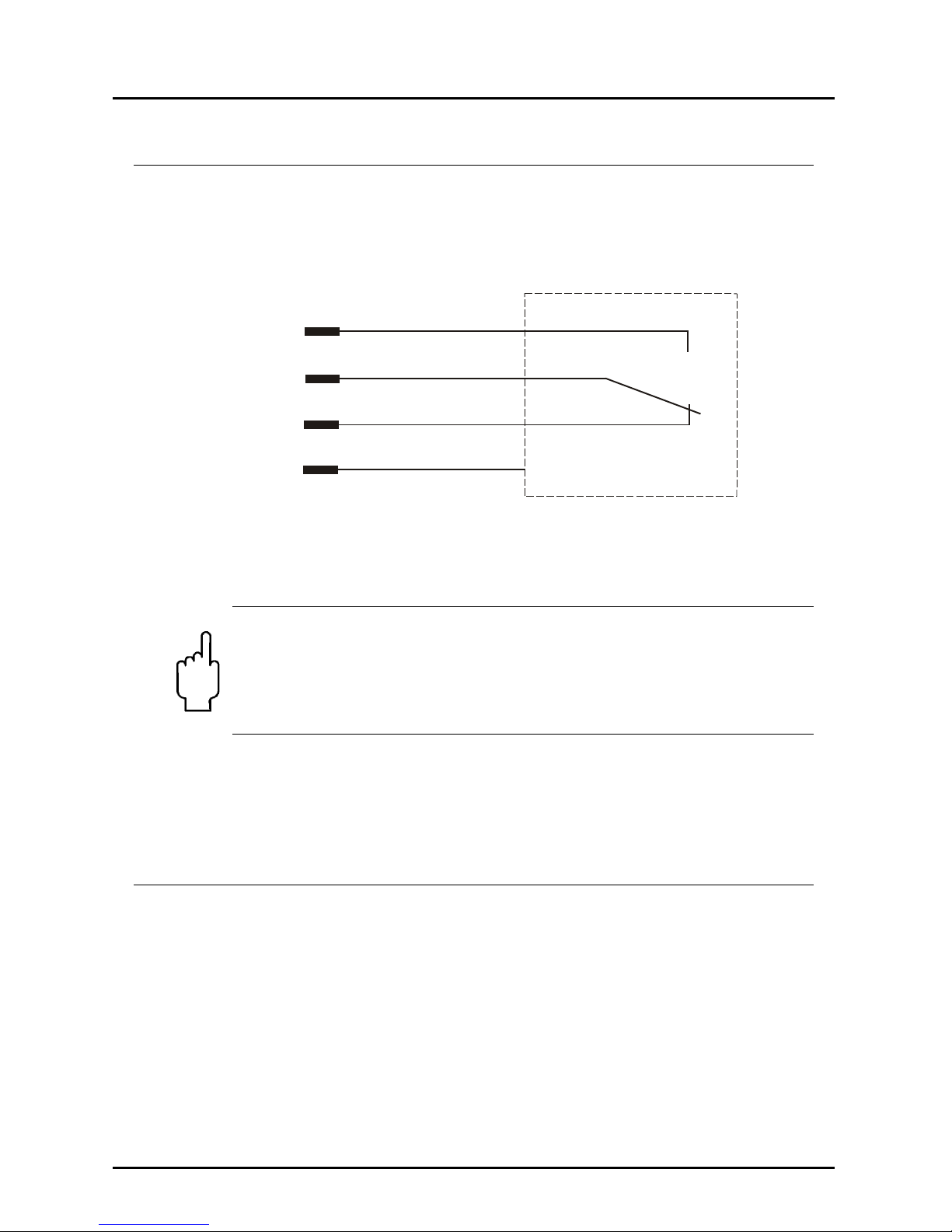
Wiring
Blue
Brown
Black
Green-yellow
N.O
.
N.C.
Yellow-green: Ground
Blue-brown: N.O. with increasing level
Brown-black: N.C. with increasing level
Note! Water can penetrate the cut-end jacketing of the cable and
seep along the line into the switch. Do not allow the liquid to rise
above this end. The wiring should be connected either in a dry area
or in a junction-box, satisfying the safety class IP65 requirement (or
better).The use of a ground-fault-interrupting circuit breaker is
recommended.
After connecting desired external devices to the limit-contact, the device is ready
for use.
8. Maintenance
Providing that, the medium to be measured is not contaminated, the NSM unit is
maintenance-free.
Page 6
NSM
Page 6 NSM K01/1016
9. T echnical Information
Material: float polypropylene
cable gland polyamide
Cable: standard: 2 m neoprene
option: silicone
Max. pressure: 3 bar
Max. temperature: 60 °C neoprene
95 °C silicone cable
Medium density: > 0.6 kg/ l
Contact: microswitch,
function changeover contact
Switch capacity: max. 250 VAC, max. 2 A
Class of protection: IP 68
Hysteresis: min. 140 mm
max. 500 mm
10. Order Codes
Example: NSM-02NEO
Description
Order no.
Standard: 2 m neoprene cable
NSM-O2 NEO
Option: silicone-rubber-insulated non-sheathed cable
NSM-YY SIL
Please specify cable length in clear text.
Page 7
NSM
NSM K01/1016 Page 7
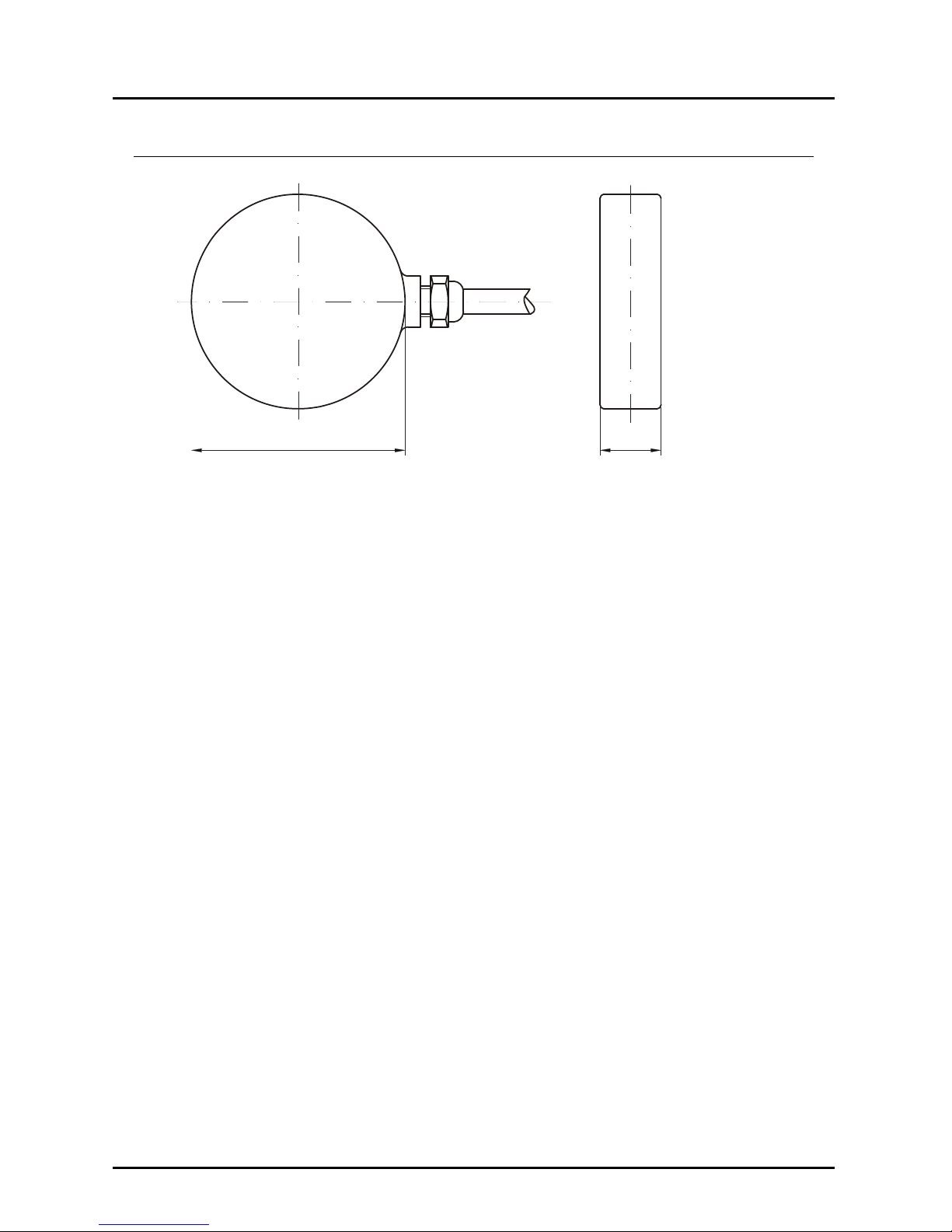
11. Dimensions
30100
Page 8

NSM
Page 8 NSM K01/1016
12. EU Declaration of Conformance
We, Kobold-Messring GmbH, Hofheim-Ts., Federal Republic of Germany,
declare that the product
Float Switch Type: NSM...
to which this declaration relates is in conformity with the standards noted below:
EN 60730-1:2012 Automatic electrical controls for household and similar use -
Part 1: General requirements
EN 60730-2-15:2011 Automatic electrical controls for household and similar use -
Part 2-15: Particular requirements for automatic electrical air flow, water flow and
water level sensing controls
Also the following EC guidelines are fulfilled:
2014/35/EU Low Voltage Directive
2011/65/EU RoHS
Hofheim, 01. Dec. 2016
H. Peters M. Wenzel
General Manager Proxy Holder
 Loading...