

Kobold NSC Operating Instructions Manual

Operating Instructions
For
Capacitance Level
Model: NSC

NSC
1. Content
1. Content ......................................................................................................... 2
2. Note .............................................................................................................. 3
3. Instrument Inspection .................................................................................... 3
4. Description .................................................................................................... 3
5. Operating principle ........................................................................................ 3
6. Mechanical connection .................................................................................. 4
7. Electrical connection ..................................................................................... 5
8. Adjustment .................................................................................................... 6
8.1 Module replacement ............................................................................ 8
9. Models .......................................................................................................... 9
10. Technical Data ............................................................................................ 10
11. Safety Instructions (ATEX) .......................................................................... 11
12. Installation in classified zone (ATEX) .......................................................... 13
13. Label Description (ATEX) ............................................................................ 13
14. Models ATEX .............................................................................................. 14
15. Declaration of conformance ( ATEX ) .......................................................... 15
16. Declaration of conformance ........................................................................ 16
17. ATEX Certificate .......................................................................................... 17
18. NOTES ........................................................................................................ 21
Manufactured by:
Kobold Mesura S.L.U
Avda. Conflent, 68 nave 15
08915 Badalona
Tel.: +34 93 460 38 83
Fax: +34 93 460 38 76
E-Mail: info.es@kobold.com
Internet: www.kobold.com
june 2017
Page 2 DT0307

NSC
2. Note
Please read these operating instructions before unpacking and putting the unit
into operation. Follow the instructions precisely as described herein.
The devices are only to be used, maintained and serviced by persons familiar
with these operating instructions and in accordance with local regulations
applying to health & safety and prevention of accidents.
3. Instrument Inspection
Instruments are inspected before shipping and sent out in perfect condition.
Scope of delivery
The standard delivery includes:
Capacitive Level Monitor NSC
Cable gland 1x M20x1,5 ( 2 atex version )
Operating Instructions
4. Description
This level switch instruments for solids NSC, has been designed to be used in all
applications where the level of the solid must be detected in tanks and silos.
5. Operating principle
The NSC sensor together with the wall of the tank is a capacitor.
The dielectric constant of this capacitor is the air when the product (media) doesn’t
reach the sensor. When the product covers the sensor, the dielectric constant is
the product one. The electronic circuit of the NSC detects this change and
activates an output relay.
DT0307 Page 3
NSC
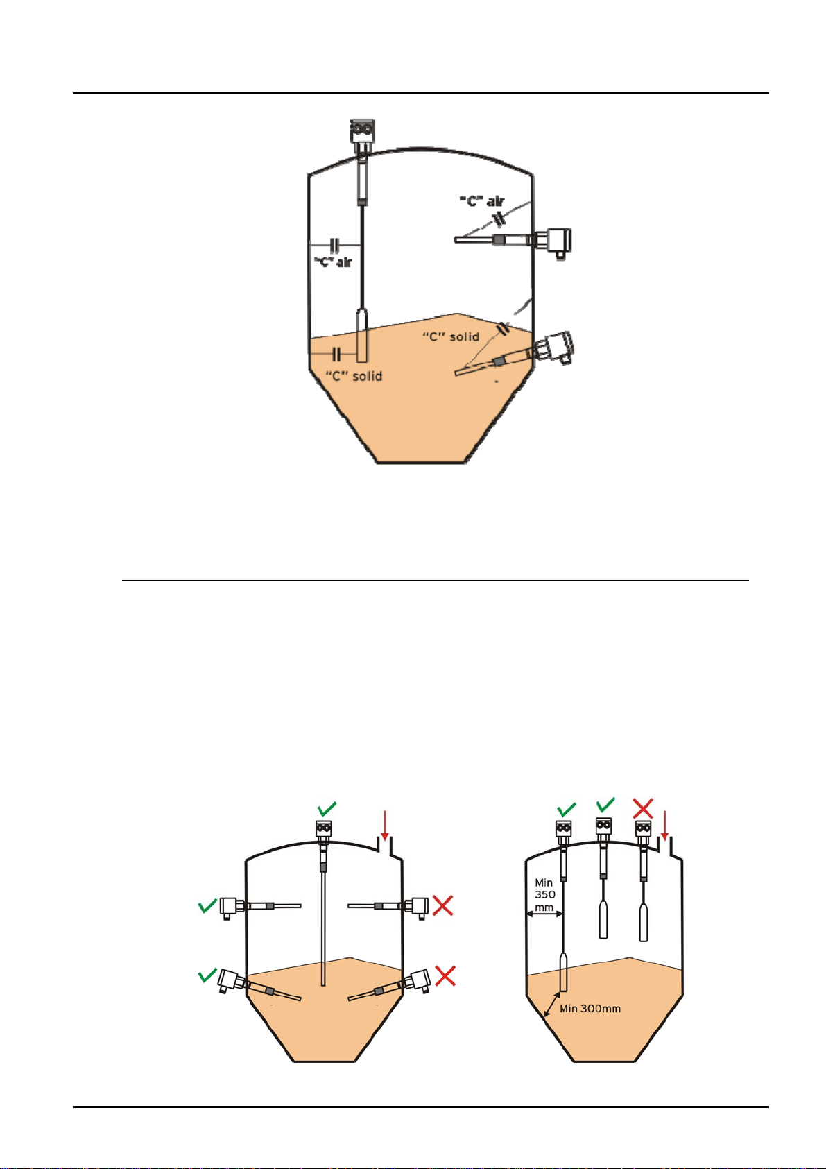
6. Mechanical connection
The NSC has a thread of 1”BSP male. The sensitive part of the probe goes from
the PP isolator to the end of the probe.
Check that lenght of probe is according the level to be detected.
When the housing is installed in the outdoor it is recommended to protect it against
sun radiation and rain by means of a small roof.
When installing the probe of the NSC by means of an extension sleeve, the max.
lenght of this sleeve must be 70mm to avoid short-circuit in between the tank and
the probe due to product accumulation inside the sleeve.
Page 4 DT0307
NSC
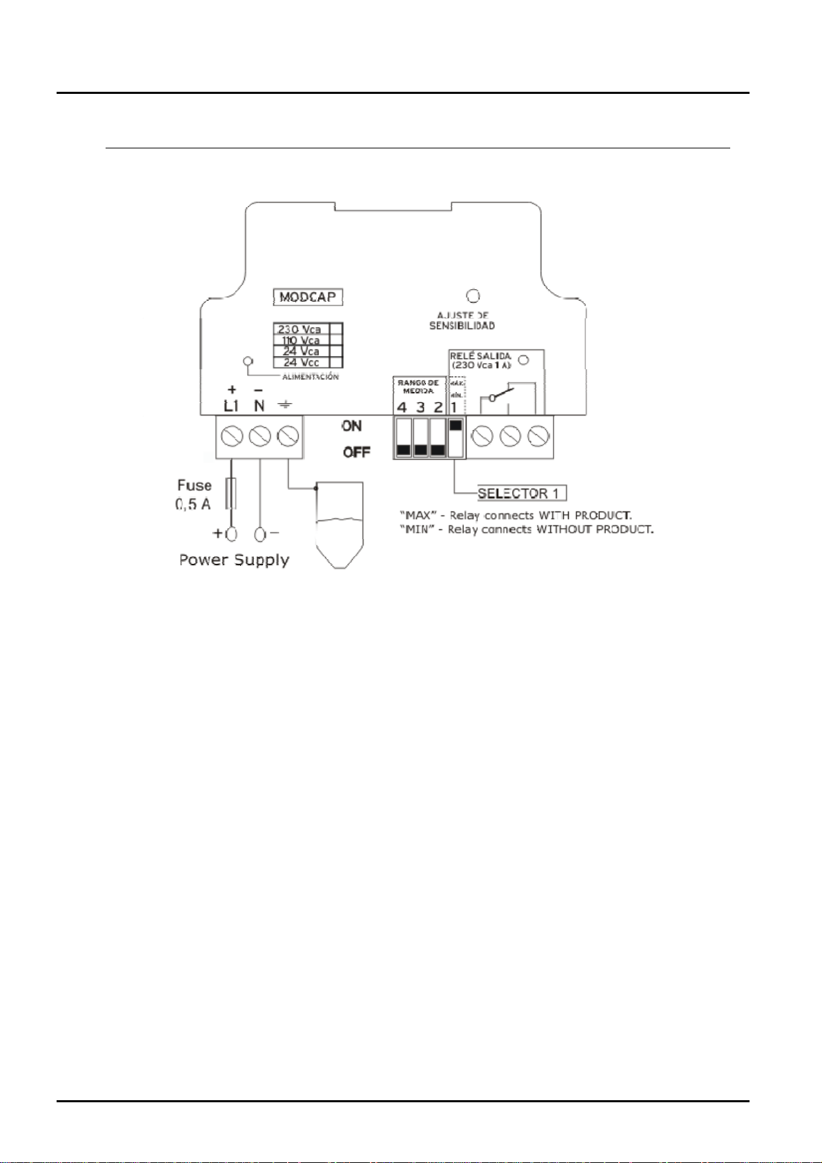
7. Electrical connection
VERY IMPORTANT
Be sure that power supply corresponds with the indicated in the equipment’s
label.
GREEN led lighting indicates that equipment is powered
RED led lighting indicates that output relay is activated.
Using SELECTOR 1, you can choose relay operation NO or NC when the
product covers the probe.
Protection fuse of 0.5mA must be put in serial with supply line.
Ground terminal is internally tied to the connection thread.
Be sure that ground line has same potential than ground of thank.
If you are not sure, please do not connect the ground terminal since the
instrument could be damaged.
DT0307 Page 5
NSC
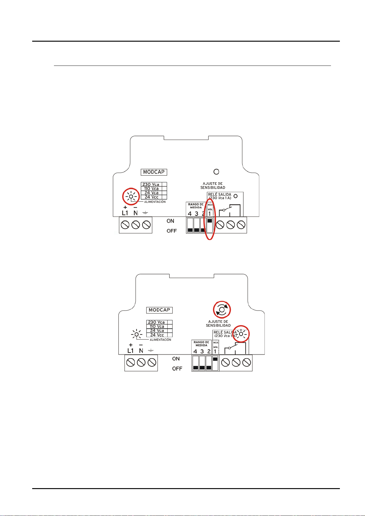
8. Adjustment
After installation and connection verification, we proceed to AJUST SENSITIVITY to fit
the NSC with the tank and the product to measure.
Check that product doesn’t reach the probe. Power supply GREEN LED must be ON
1. Put DIP-SWITCH 1 to “MAX” position.
2. Turn the “SENSITIVITY ADJUSTMENT screw” clockwise until RED LED
lights.
Page 6 DT0307
NSC
3. Turn slowly the “SENSITIVITY ADJUSTMENT screw” counter clockwise until
RED LED switches off.
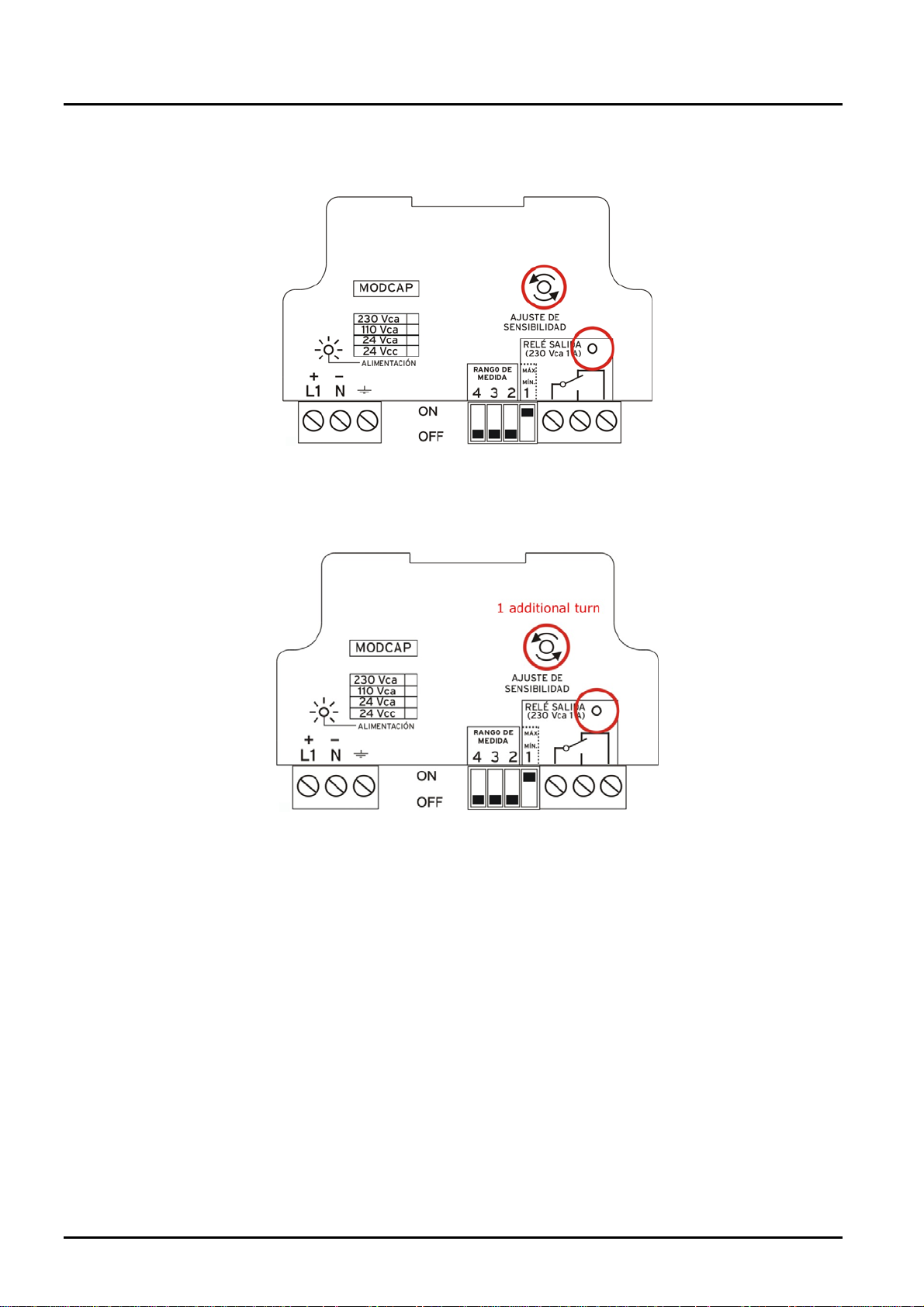
4. Turn 360º more counter clockwise to avoid a critical adjustment. In case of
sticky products it is recommended to increase this adjustment.
The instrument is now adjusted. When product will reach the probe relay will be
activated and RED LED will light.
If we want the relay to work the REVERSE, put DIP-SWITCH 1 to “MIN”.
Check that no product remains on the probe when unloading the tank.
DT0307 Page 7
NSC
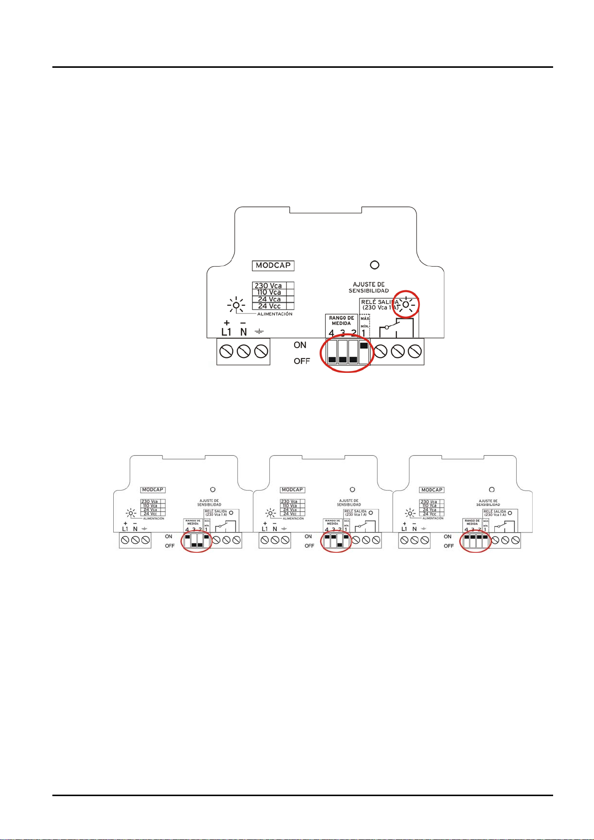
8.1 Module replacement
MODCAP modules are delivered with DIP-SWITCHES 2, 3 and 4 adjusted with its own
probe. In case of replacement, following procedure must be done with the probe free of
product:
1. With DIP-SWITCH 1 to “MAX” and 2, 3 and 4 to “MIN”, turn the multiturn
potentiometer totally to clockwise (20 turns). RED LED will switch ON.
2. In case that RED LED doesn’t lights, move DIP-SWITCH 4 (drawing 1) to
ON. If RED LED still remains OFF, do same with DIP SWITCH 3 (drawing 2)
and finally with DIP-SWITCH 2 (drawing 3) until RED LED finally lights.
Drawing 1 Drawing 2 Drawing 3
3. Once DIP-SWITCHES are correctly settled the SENSITIVITY ADJUSTMENT
must be done (chapter 8).
Page 8 DT0307
 Loading...