

Kobold NRF Instruction Manual
NRF-100_KM Rev. : 1.0 16/04/2002
Kobold two-wire NRF level transmitters
are designed to measure either liquid or
certain dry bulk media. The 12-36 VDC
4mA base current is the supply to the
unit. The NRF monitors level change by
converting movement of media UP or
DOWN the probe into pulse wave form
which is proportional to changes in
level. The amplifier converts this pulse
wave into 4 to 20 mA output signal. The
conversion of level movement to an
electrical signal is due to changes in
electrical capacitance. The probe and a
ground reference electrode, usually the
metal tank wall, have a certain capacitance in air. As the medium displaces
the air, a change occurs because of the
difference in the dielectric constants of
the medium and air.
Fig 1.
aran_v02 or higher
01/12/2002
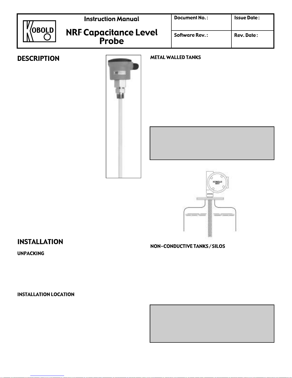
It is a common practice to use the metal tank wall as the
reference electrode. In such cases, it is required that the
probe housing makes a good electrical connection to the
tank wall. If there is any doubt about this connection due
to the use of PTFE thread tape, gaskets, paint, rust, or
any other reason, a separate grounding wire should be
installed between the probe and the tank housing. In case
the probe housing is non-metalic, or if the connection
fitting is non-metalic, a grounding wire must be connected
from the tank to the G terminal on the transmitter.
CAUTION: This unit contains CMOS electronics which
may be damaged by static electricity. Electronics may
be accessed by removing the top cover of the enclosure
(head). Do not remove the transmitter face plate (and
touch the electronics). There are no servicable parts.
The NRF comes complete with the transmitter mounted in
an enclosure, fitting and probe (Fig. 1). Micro-processor
based electronics are protected and potted within a metal
housing. Calibration is made via four push buttons
(Fig. 3) as explained later. Variety of options including
Stainless or PVC housings, rigid or flexible probes (bare
or jacketed), NPT, sanitary or flange connections are
available.
Unpack the instrument carefully. Inspect all components
for damage. Report any damage to Kobold within 24
hours. Check the contents of the packing slip and report
any discrepencies to Kobold.
The Kobold NRF level sensor should be located for easy
access for service, calibration and monitoring. Sensors
should not be exposed to ambient temperatures below
- 4 0°C (- 4 0° F) or above +70°C (+ 1 6 0° F). Special precau tion
should be made to prevent exposure to corrosive
atmosphere, excessive vibration, shock or physical
damage. It is preferable that the NRF is not installed in
proximity to high voltage wires or other sources of high
electrical noise.
Fig 2.
With plastic, concrete, wood, or any other non-conductive
walled vessels a reference electrode must be inserted
into a tank. Most commonly, this electrode will be in the
form of a concentric, ground tube (i.e. stilling well, Fig. 2)
or a metal rod installed in parallel with the probe. In all
cases, a good electircal connection must be made
between the ground reference electrode and the G
terminal of the transmitter (or probe housing).
CAUTION: When installing units with PTFE (or plastic)
coated rods or cables, be careful not to damage the
insulation. NPT threads have very sharp corners and
PTFE (or plastic) can be easily cut. In acidic and/or
conductive liquids damaged units may malfunction and
the metal rods can corrode
Page 1
NRF-100_KM Rev. : 1.0 16/04/2002
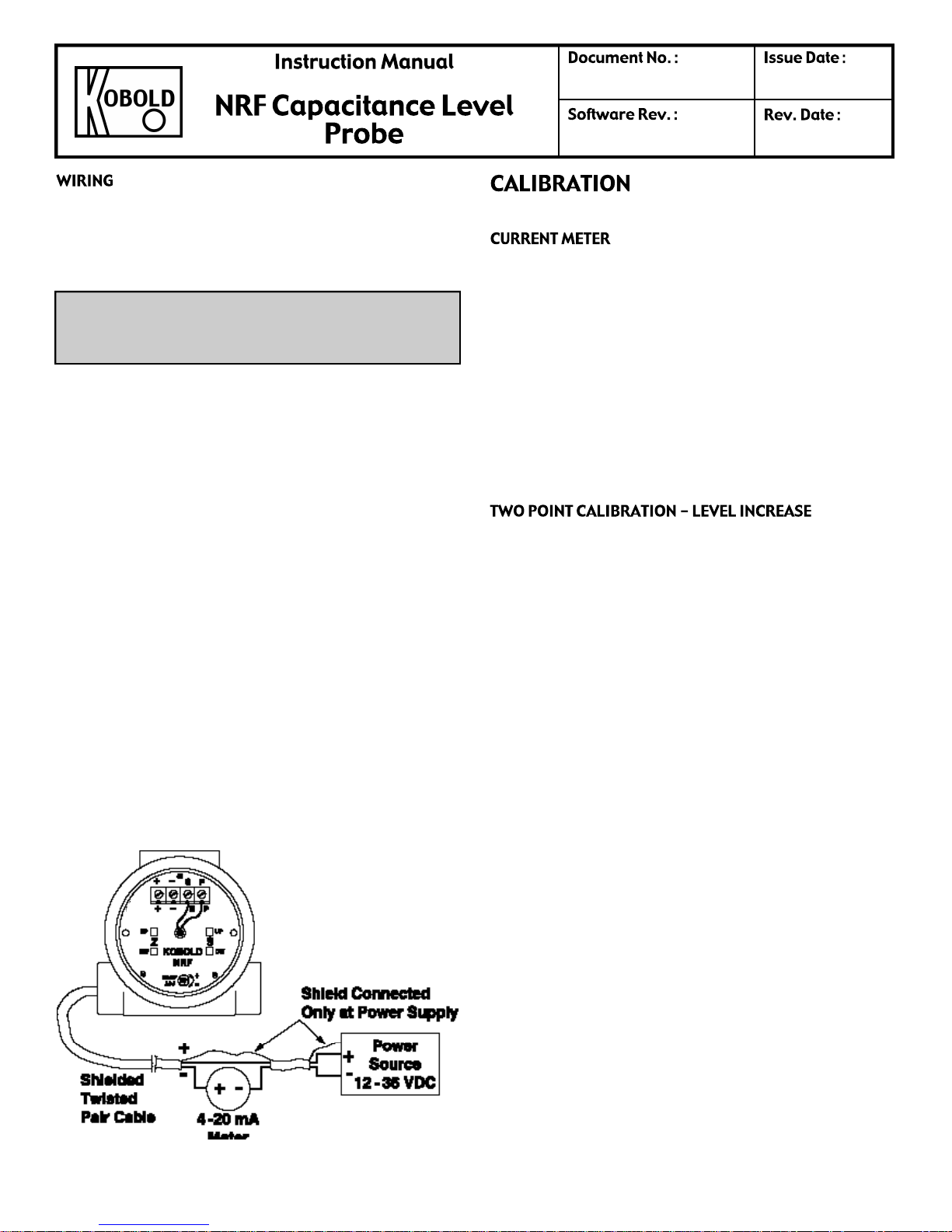
All wiring between the power supply and the transmitter
should be done with 18 AWG to 22 AWG shielded twisted
pair. The connection is made at the terminal strip within
the transmitter enclosure.
CAUTION: Units are designed to operate on the 12 to
36 VDC power only. Application of 110 VAC will destroy
the instrument.
1. Make sure the power source is turned off.
2. Pull power supply wires through conduit connection.
3. Connect the positive supply wire to the (+) terminal,
and the negative supply to the (-) terminal.
Note: Leave shield unattached at transmitter.
Connect the shield to ground at the power source.
4. Replace the transmitter enclosure (head) cover until
time to calibrate.
5. Connect positive supply wire to the positive terminal
of the transmitter. See Fig. 3.
6. Connect the loop current meter in series with the
negative supply wire as follows:
a. Negative transmitter wire to positive meter
terminal. See Fig. 3.
b. Negative meter terminal to negative power
source termianl. See Fig.3.
7. Turn ON the power. The meter may read anywhere
on the scale at either end. This is normal until calibra
tion has been completed. Proceed to the calibration
Instructions.
aran_v02 or higher
01/12/2002
In order to calibrate the transmitter, you must use the loop
current meter. It should read currents in the range of 1.00
to 25.00 mA, with a resolution of .01 mA. Using a meter
of less resolution will somewhat reduce the calibration
accuracy. To calibrate the instrument :
1. Remove enclosure (head) cover.
2. Connect the loop current meter as per instructions in
WIRING section(Fig. 3).
3. The loop current should now be in the range of 1.5
mA to 38 mA, which is normal at this point.
Three calibration procedures are described. Follow the
one which fits your application. Note the following definitions used in the calibration procedures, referring to Fig 4.
L = the level of material which corresponds to 4.00 mA of
loop current, i.e., the 0%
L1 = a material level higher than L
H1 = a material level higher than L1, but less than H.
H = the level of material in the vessel which corres-
ponds to 20.00 mA of loop current, i.e., the 100% level.
Note: To avoid the possibility of a “dead zone”, L must be
at least two (2) inches above the end of the probe for (4)
conductive media and four inches above for nonconductive media.
Page 2
CALIBRATION L- H = when material in tank can be set
to L (0%) and H (100%).
CALIBRATION L - H1 = when material in tank can be set
to L (0%) and H1 (less than 100 %).
CALIBRATION L1 - H1 = when material in tank can be
set to L1 (greater than 0 %) and H1 (less than 100%).
NOTE: Calibration procedure L-H gives the most
accurate results and is the recommended procedure in
all cases.
Fig. 3
 Loading...