

Kobold NQ series Installation & Operation Instructions
Specifications
Series NQ Ultrasonic Level Switch
Installation/Operation Instructions
Power Requirements:
Two Wire Switching: 24 to 240 VAC/VDC 50-60 Hz.
Three Wire Switching: 24 VDC
KOBOLD Instruments, Inc. 1801 Parkway View Drive, Pittsburgh PA 15205
Telephone: (412) 788-2830 · FAX: (412) 788-4890 www.koboldusa.com
Description
KOBOLD’s Series NQ level switch is a compact, ultrasonic
gap level switch which is suited for use with low-viscosity,
non-coating liquids. The switch employs an ultrasonic
transmitter and receiver in the switch probe. When the probe
is immersed in liquid, the gap fills, resulting in the ultrasonic
transmitter being acoustically coupled to the receiver. This
acoustic coupling is sensed by a detection circuit and results
in the activation of the integral, solid-state switch. The solidstate switch can be configured either as a two-wire or threewire controller. The unit is adjustable from a normally-open
to normally-closed (wet-on or dry-on) switch function via an
internal selector switch. Its solid-state design uses no
moving parts in the sensor or switch portions, making the
NQ level switch exceptionally reliable.
Solid State Switch Characteristics:
Max. Current: 500 mA.
Min. Current: 7.5 mA.
Leakage Current: 3 mA.
Voltage Drop: 4.5 Volts @ 500 mA.
10 Volts @ 7.5 mA.
Installation
1.) In order to ensure a leak-tight seal, a thread sealant such as
Teflon tape (or other appropriate thread sealant) should be used on
the probe threads prior to installation.
2.) The NQ must always be installed with the cable penetration facing
downward (between the 5 O’Clock to 7 O’Clock position) and creating
a drip loop with the cable. This will minimize the possibility of water
entering the cable gland thereby minimizing the possibility of water
migration into the electronics. After the unit is installed into the
process fitting, the housing may be rotated to achieve the proper
cable gland orientation.
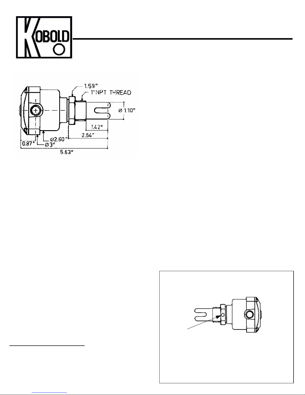
Probe Orientation Installation Note:
To ensure reliable operation, the NQ-2000 must be installed into the
vessel with the forks of the sensing probe in the 3 O’Clock and 9
O’Clock position. This will minimze any air bubbles that could collect
in the gap and interfere with the acoustic coupling. The installation
nut on the NQ has a guide dot or drilling which can be used to ensure
that the probe is installed in the proper position (See Fig. 2).
Switching Delay:
Wet to Dry: 500 mSec.
Dry to Wet: 150 mSec.
Fluid Temperature Range: -40 to 250°F
Max. Ambient Temp: 120°F with 250°F Fluid
Max. Operating Pressure: 290 PSIG @-40 to 250°F
Electrical Protection: IP 65
Fig. 2: Probe Orientation
Guide Dot
(Bottom View)
The guide dot or drilling on the probe installation
nut should be located in the 12 O’Clock or 6 O’Clock
position to ensure that the probe is properly
oriented inside the tank.
24-240 VAC/VDC
Wire Color Codes on Mating Connector
Brown = 1 = +24 VDC (+VE)
White = 2 = Equipment Ground
Blue = 3 = -DC Ground (-VE)
Black = 4 = Signal Out (A)
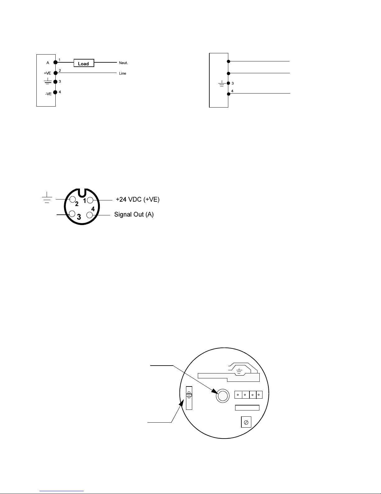
Electrical Connections
-DC Gnd. (-VE)
Fig. 3 Two-Wire Connection
The two-wire configuration switches line
voltage to the load device when switch
is activated. The load device is connected
in series with the NQ.
WARNING: ALWAYS CONNECT THE LOAD PRIOR TO
APPLYING POWER OR DAMAGE TO THE NQ WILL RESULT!
Fig. 5 Plug Connector Pinout (option -M12) 24 VDC only!
Fig. 4 Three-Wire Connection
+VE
-VE
1
A
2
Output
+
24 VDC In
-
The three-wire configuration switches
+24 VDC to the output when the NQ is
activated.
Operation
Status Indicator
Flashing: Switch not activated (open switch)
Steady: Switch activated (closed switch)
Logic Selector Switch
for normally open or
normally closed operation
LOAD/CHARGE/LAST
AC/DC 24-240 V
DRY-ON
VIOE
LEER
WET-ON
PLEIN
VOLL
-VE
+VE A
4
2 13
Rev. 1/12/15
 Loading...