

Page 1
Operating Instructions
for
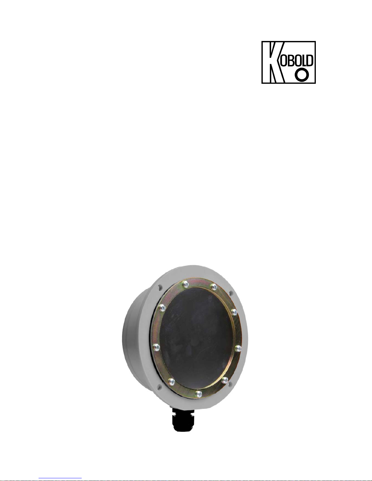
Membrane Level Monitor
for Bulk Goods
Model: NMF
Page 2

NMF
page 2 NMF K04/0218
1. Contents
1. Contents ........................................................................................................ 2
2. Note .............................................................................................................. 3
3. Instrument Inspection .................................................................................... 3
4. Regulation Use .............................................................................................. 3
5. Operating Principle ........................................................................................ 4
6. Mechanical Connection ................................................................................. 5
6.1 Installation with very coarse-grained and sharp-edged bulk goods ..... 5
7. Electrical Connection .................................................................................... 6
7.1 Connection diagram ............................................................................. 6
8. Technical Information / Configuration ............................................................ 7
8.1 Model NMF-E... configuration standard ............................................... 7
8.2 Model NMF-F...configuration for greater wall thicknesses ................... 7
8.3 Model NMF-D...configuration with double-membrane .......................... 8
8.4 Model NMF-B...configuration for higher temperatures ......................... 8
9. Order Codes ................................................................................................. 9
9.1 NMF-E ................................................................................................. 9
9.2 NMF-F .................................................................................................. 9
9.3 NMF-D ................................................................................................. 9
9.4 NMF-B ................................................................................................. 9
10.Dimensions ................................................................................................. 10
10.1 NMF-E... ............................................................................................ 10
10.2 NMF-F... ............................................................................................. 10
10.3 NMF-D... ............................................................................................ 11
10.4 NMF-B... ............................................................................................ 11
11.EU Declaration of Conformance .................................................................. 12
Manufactured and sold by:
Kobold Messring GmbH
Nordring 22-24
D-65719 Hofheim
Tel.: +49(0)6192-2990
Fax: +49(0)6192-23398
E-Mail: info.de@kobold.com
Internet: www.kobold.com
Page 3

NMF
NMF K04/0218 page 3
2. Note
Please read these operating instructions before unpacking and putting the unit
into operation. Follow the instructions precisely as described herein.
The devices are only to be used, maintained and serviced by persons familiar
with these operating instructions and in accordance with local regulations
applying to Health & Safety and prevention of accidents.
When used in machines, the measuring unit should be used only when the
machines fulfil the EC-machine guidelines.
3. Instrument Inspection
Instruments are inspected before shipping and sent out in perfect condition.
Should damage to a device be visible, we recommend a thorough inspection of
the delivery packaging. In case of damage, please inform your parcel service /
forwarding agent immediately, since they are responsible for damages during
transit.
Scope of delivery:
The standard delivery includes:
Membrane Level Monitor model: NMF
Operating Instructions
4. Regulation Use
Any use of the Membrane Level Monitor, model: NMF, which exceeds the
manufacturer’s specifications, may invalidate its warranty. Therefore, any
resulting damage is not the responsibility of the manufacturer. The user assumes
all risk for such usage.
Page 4

NMF
page 4 NMF K04/0218
5. Operating Principle
Membrane level monitors allow economic level monitoring of bulk goods in
storage vessels. They may be used to indicate full and empty states and load
demand for dusty, powdery, granulated and grainy bulk goods. They are suitable
for use with bulk materials (0.3 to 2.5 t/m3) and particle sizes up to 30 mm. The
devices will operate faultlessly provided the bulk goods flow easily at not too
small an angle. Only such materials exert sufficient operating pressure on the
detector fitted in the wall of the silo.
The housing made of cast aluminium or glass-fibre reinforced plastic carries the
membrane retained by a screwed-on ring. With its own weight the bulk material
presses against the membrane which is prestressed with a spring through to the
support. A plunger fixed to the membrane transfers the pressure directly to a
microswitch with changeover contact. If the bulk material subsides, the
membrane is relieved and the contact is switched back. The sensitivity can be
adjusted with a spring. The monitor can thus be optimised for the type of fill and
the installation conditions.
Page 5

NMF
NMF K04/0218 page 5
6. Mechanical Connection
6.1 Installation with very coarse-grained and sharp-edged bulk
goods
The installation of guards is recommended for very large grained and sharpedged materials with high specific weight.
A proposal for such a guard is
shown in the sketch. The guard
mounted over the level monitor
protects sensor and membrane
against damage from dropping bulk
material. The curtain (made of
rubber or plastic, for instance) protects
the membrane from excessive
wear by hanging against the membrane
as the amount of bulk material
increases. Make sure that
the monitor is not in the path of
the inflowing material, as otherwise
monitor and membrane would be
destroyed very quickly.
Page 6

NMF
page 6 NMF K04/0218
7. Electrical Connection
7.1 Connection diagram
Attention! Make sure that the voltage values of your system
correspond with the voltage values of the measuring unit.
Make sure that the supply wires are de-energised.
Plug in the system according to the connecting diagrams.
Attention! Incorrect wiring will lead to damage of the unit’s
electronics.
NONC C
P
3 or 4
Page 7

NMF
NMF K04/0218 page 7
8. Technical Information / Configuration
8.1 Model NMF-E... configuration standard
Materials: Membrane made of nitrile or FPM
retaining ring in galvanised steel
or stainless steel 1.4324
housing in glass-fibre-reinforced
plastic GRP
Weight: 480 g
Sensitivity: adjustable between 60 g and 200 g
Protection: IP 40 screwed fitting bottom
IP 53 screwed fitting top
Contact loading: max. 4 A at 250 VAC
Temperature range: -20 ... +60 °C
Max. pressure: depressurised, overpressure max. 1 bar
Cable entry fitting: M20 x 1.5
Switch-in delay: 0 s
Installation position: any
8.2 Model NMF-F...configuration for greater wall thicknesses
Materials: Membrane made of nitrile or FPM
retaining ring made of galvanised
steel or stainless steel 1.4324
housing in glass-fibre-reinforced
plastic GRP
Weight: 530 g
Sensitivity: adjustable between
60 g and 200 g
Protection: IP 40 screwed fitting bottom
IP 53 screwed fitting top
Contact loading: max. 4 A at 250 V
AC
Temperature range: -20 ... +60 °C
Max. pressure: depressurised, overpressure max. 1 bar
Cable entry fitting: M20 x 1.5
Switch-in delay: 0 s
Installation position: any
Page 8

NMF
page 8 NMF K04/0218
8.3 Model NMF-D...configuration with double-membrane
Materials: Membrane in nitrile or FPM
retaining ring made of galvanised
steel or stainless steel 1.4324
housing in glass-fibre-reinforced
plastic GRP
Weight: 750 g
Sensitivity: adjustable between 60 g and 200 g
Protection: IP 65
Contact loading: max. 4 A at 250 V
AC
Temperature range: -20 ... +70 °C
Max. pressure: depressurised, overpressure max. 1 bar
Cable entry fitting: M20 x 1.5
Switch-in delay: 0 s
Installation position: any
8.4 Model NMF-B...configuration for higher temperatures
Materials: Membrane made of NBR, FPM
or stainless steel 1.4301
retaining ring in cast aluminium
housing in cast aluminium
Weight: 1700 g
Sensitivity: adjustable between 100 g and 200 g
(NMF-BNA, NMF-BVA)
adjustable between 200 g and 500 g
(NMF-BEA)
Protection: P 40 screwed fitting top
IP 53 screwed fitting bottom
Contact loading: max. 4 A at 250 V
AC
Temperature range: Membrane NBR -20 ... +80 °C
FPM -20 ...+150 °C
st. steel -20 ... +200 °C
Max. pressure: depressurised, overpressure max. 1 bar
Cable entry fitting: M20 x 1.5
Switch-in delay: 0 s
Installation position: any
Page 9

NMF
NMF K04/0218 page 9
9. Order Codes
9.1 NMF-E
Order Details (Example: NMF-ENN)
Membrane Retaining ring Order no.
Nitrile
Galvanised steel
NMF-ENN
St. steel 1.4324
NMF-ENE
FPM
Galvanised steel
NMF-EVN
St. steel 1.4324
NMF-EVE
9.2 NMF-F
Order Details (Example: NMF-FNN)
Membrane Retaining ring Order no.
Nitrile
Galvanised steel
NMF-FNN
St. steel 1.4324
NMF-FNE
FPM
Galvanised steel
NMF-FVN
St. steel 1.4324
NMF-FVE
9.3 NMF-D
Order Details (Example: NMF-DNN)
Membrane Retaining ring Order no.
Nitrile
Galvanised steel
NMF-DNN
St. steel 1.4324
NMF-DNE
FPM
Galvanised steel
NMF-DVN
St. steel 1.4324
NMF-DVE
9.4 NMF-B
Order Details (Example: NMF-BNA)
Membrane Retaining ring Order no.
NBR Cast aluminium
NMF-BNA
FPM Cast aluminium
NMF-BVA
St. steel Cast aluminium
NMF-BEA
Page 10

NMF
page 10 NMF K04/0218
10. Dimensions
10.1 NMF-E...
10.2 NMF-F...
Page 11

NMF
NMF K04/0218 page 11
10.3 NMF-D...
10.4 NMF-B...
Page 12

NMF
page 12 NMF K04/0218
11. EU Declaration of Conformance
We, KOBOLD Messring GmbH, Hofheim-Ts, Germany, declare under our sole
responsibility that the product:
Membrane Level Monitor Model: NMF-...
to which this declaration relates is in conformity with the standards noted below:
EN 61010-1:2010 Safety requirements for electrical equipment for
measurement, control and laboratory use - Part 1: General requirements
EN 60529:2013 Degrees of protection provided by enclosures (IP Code)
Also the following EC guidelines are fulfilled:
2014/35/EU Low Voltage Directive
2011/65/EU RoHS (category 9)
Hofheim, 27. Febr. 2018
H. Peters M. Wenzel
General Manager Proxy Holder
 Loading...