

Kobold NMC Series, NMC-N, NMC-H, NMC-T, NMC-S Operating Instructions Manual

Operating instructions
for
Capacitive level transmitter
Model NMC
2 Wire (4 to 20mA)

NMC
1. Content
1. Content ......................................................................................................... 2
2. Note .............................................................................................................. 3
3. Instruments inspection .................................................................................. 3
4. Description ................................................................................................... 3
5. Application .................................................................................................... 3
6. Current simulation ........................................................................................ 4
7. Installation .................................................................................................... 4
8. Electrical connection ..................................................................................... 5
9. Programming ................................................................................................ 6
9.1 Calibrating probe ................................................................................. 6
9.2 Output Adjustment .............................................................................. 7
9.3 Output simulate ................................................................................... 8
9.4 Language ............................................................................................ 9
10. Technical Data............................................................................................ 10
11. Safety Instructions (ATEX) ......................................................................... 11
11.1 Validity ............................................................................................... 11
11.2 General considerations ..................................................................... 11
11.3 Protection against ESD (electro static discharges) ........................... 11
11.4 Chemical resistance .......................................................................... 12
12. Installation in classified zone (ATEX) ......................................................... 12
13. Label Description (ATEX) ........................................................................... 12
14. Declaration of conformance ATEX ............................................................. 13
15. Declaration of conformance ........................................................................ 14
16. ATEX Certified ............................................................................................ 15
17. Models ........................................................................................................ 20
18. Order details. .............................................................................................. 21
19. Notes .......................................................................................................... 22
Manufactured by:
Kobold Mesura S.L.U
Avda Conflent Nº68 Nave 15
08915 Badalona
Tel.: +34 93 460 38 83
Fax: +34 93 460 38 72
E-Mail: info.es@kobold.com
Internet: www.kobold.com
Edition: june 2017
Páge 2 DT0305

NMC
2. Note
Please read these operating instructions before unpacking and putting the unit into
operation. Follow the instructions precisely as described herein.
The devices are only to be used, maintained and serviced by persons familiar with
these operating instructions and in accordance with local regulations applying to
health & safety and prevention of accidents.
3. Instruments inspection
Instruments are inspected before shipping and sent out in perfect condition.
Scope of delivery
The standard delivery includes:
Capacitive Level Transmitter NMC
Cable gland M20
Operating Instructions
4. Description
The NMC transmitter is a two wire capacitance level transmitter for measuring
continuous level in tanks containing liquids.
5. Application
The probe of the NMC and the wall of the tank, forms an electric capacitor. The
dielectric of this capacitor when the tanks is empty, is the air.
When the liquid reaches the probe, the dielectric constant formed by the unit and
tank, changes.
An electronic circuit sited in the connecting module of NMC, converts this capacity
change in a variable current and proportional to the height of the liquid.
Due to each application is different, given that the kind and the measures of the
tank and the products that it contains change, every unit has to be adjusted to be
adapted to each tank and product.
Using the menus of the NMC , this operation is very easy.
The circuit, controled by microprocessor, stores all data and does the calculation. A
display LCD guides us in the calibration process.
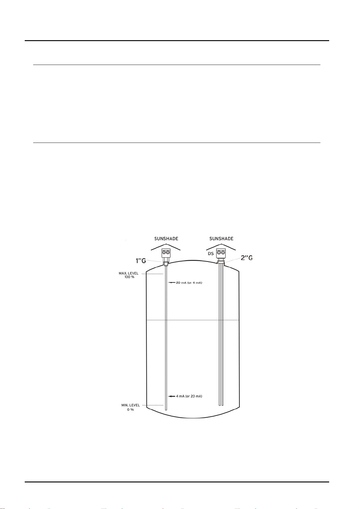
The output current signal is 4 to 20 mA. These values can be sited where we want
in the probe.
DT0305 Page 3
NMC
6. Current simulation
Using this option the NMC generates in the supply loop, a 4 to 20 mA current, in
steps of 1 mA. This function is very useful to make tests with independence of the
level of the tank.
7. Installation
The NMC is installed using a G1” (G2” in DS version).
The probe must be installed avoiding a good contact between the probe and the
tank’s wall.
Electronic of the NMC unit should be protected with shelter against development of
too high temperature by direct sunshine.
Be ensured that the connection to the tank has been done properly. The NMC ’s
thread should not been forced.
The electrical connection between the thread and the tank has to be good.
Páge 4 DT0305
NMC
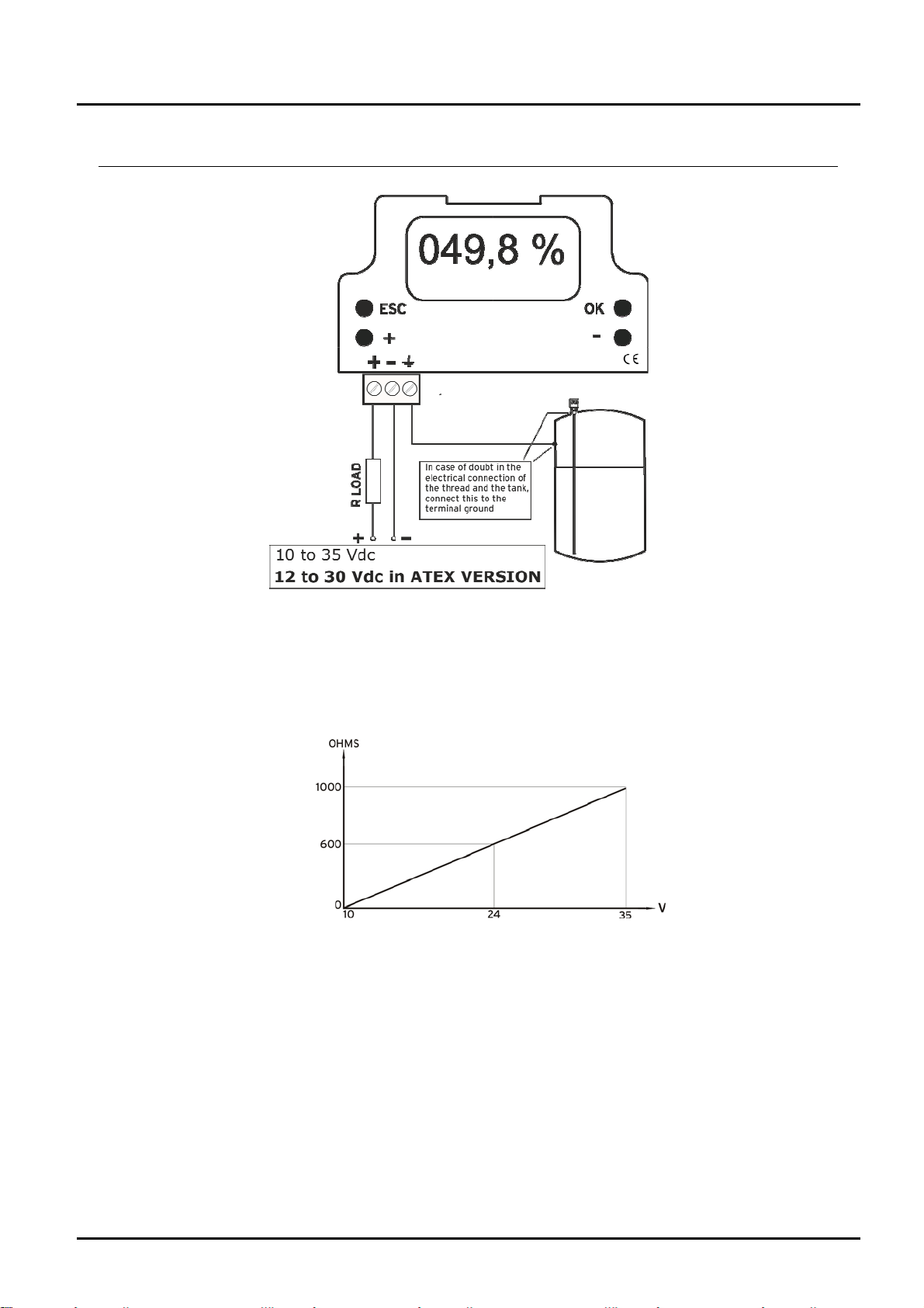
8. Electrical connection
The maximum resistance of the line in serial depends on the power supply. These
values have to be bear in mind for the good run of the NMC.
DT0305 Page 5

NMC
9. Programming
9.1 Calibrating probe
Calib.Probe OK
Output +
Language Back ESC
CALIBRATION
¿SURE?
YesOK NoESC
CALIBRATION
Low Level OK
High Level +
LOW LEVEL ADJUST
Enter the actual level in probe.
+And-: 010.0 % OK
Calibrating
PROBE
For low level
….WAIT….
***PROBE
CALIBRATED**
Calib.Probe OK
Output +
Language -
Back ESC
1. Pressing any key, you enter in the main menú.
Press (OK) to enter in calibration probe.
2. To avoid mistakes, asks again if you are sure that
you want to calibrate the unit. Press (OK) another
time to enter.
3. If the level in the tank is low, we will choose the
(OK) option to adjust the unit with the lowest level
4. If, for example, when you adjust the low level, the
level of the tank is the 10 % of the capacitance, we
will indicate it in the display using the ( + ) and ( - )
keys. Confirm with ( OK ).
5. In this moment the microprocessor makes the
operations to choose the best measurement range.
This operations takes some seconds.
6. When this operation is finished, the display shows
the message “PROBE CALIBRATED”.
7. Automatically the display shows the main menu.
Now need calibrate the High Level, then pressing
(OK) another time to enter in the calibration probe
menu.
Páge 6 DT0305

NMC
CALIBRATION
¿SURE?
Yes OK No ESC
CALIBRATION
Low Level OK
High Level +
HIGH LEVEL ADJUST
Enter the actual level
In probe
+ and - :080.0 % OK
Calibrating
PROBE
For low level
…. WAIT ….
*** PROBE
CALIBRATED ***
Calib.Probe OK
Output +
Language Back ESC
8. To avoid mistakes, asks again if you are sure that
you want to calibrate the unit. Press ( OK ) another
time to enter.
9. Pressing (+) we enter in High level calibration.
10. If when you adjust the high level, the liquid in the
tank is 80 % of the capacitance, we will indicate it in
the display using the (+) and (-) keys. Confirm with
(OK).
11. The microprocessor makes the operations to
calibrate the maximum level of the unit. This
operation takes some seconds.
12. The display shows this message to indicate NMC
has finished the calibration internal process.
When the liquid level will be in the minimum point, it
will indicate 000.0 % and when the liquid level will
be in the maximum, 100.0 %.
13. Automatically, the display shows the main menu.
Pressing ESC the unit returns to read state.
Pressing (+) we can enter in output adjustment
menu and simulation mode.
9.2 Output Adjustment
Calib.Probe OK
Output +
Language Back ESC
OUTPUT
Output SIM -
Output Adj +
Back ESC
DT0305 Page 7
1. Pressing any key, you enter in the main menu.
Press (+) to enter in Output.
2. Pressing (+), we enter in Output adjustment menu.

NMC
¿Where do you want the 4
¿Where do you want the 20
+ and - : 1 OK
Output SIM -
Output Adj +
Back ESC
OUTPUT ADJUST
mA output?
+ and - : 005.0 % OK
OUTPUT ADJUST
mA output?
+ and - : 095.0 % OK
MEASURE FILTER
Enter filter’s level
0 to 5
OUTPUT
049.8%
12.04 mA
3. This asks, where do you want the NMC gives us 4
mA. If you want it in 5 % of the probe. Using (+) and
(-) we indicate this value in the display. Confirm with
(OK)
4. We do the same for the 20 mA. In this case, if we
want this current in the 95 % of the probe, we will
indicate this value using (+) and (-).
Confirm with (OK)
5. Finished the adjustment, we can incorporate a filter
to avoid oscillations caused by quick movements of
the liquid’s surface. This value between 0 and 5
(maximum filter). Confirm with (OK)
6. Automatically return to output menu.
Pressing ESC return to measuring mode.
7. In this point, the NMC is adjusted. The number in
% indicates the height that reaches the level in the
probe (0 to 100). The value of the current will
depends f the adjustment of the points 3 and 4 of this
section, and it can be in any point of the probe. It
can be in maximum point and in the 20 mA at the
minimum.
9.3 Output simulate
Calib.Probe OK
Output +
Language Back ESC
OUTPUT
Output SIM -
Output Adj +
Back ESC
Páge 8 DT0305
1. Pressing any key, you enter in the main menu.
Press (+) to enter in Output.
2. Pressing (-), we enter in simulate output menu.
 Loading...