

Page 1

Operating instructions
for
Capacitive level transmitter
Model NMC
2 Wire (4 to 20mA)
Page 2

NMC
1. Content
1. Content ......................................................................................................... 2
2. Note .............................................................................................................. 3
3. Instruments inspection .................................................................................. 3
4. Description ................................................................................................... 3
5. Application .................................................................................................... 3
6. Current simulation ........................................................................................ 4
7. Installation .................................................................................................... 4
8. Electrical connection ..................................................................................... 5
9. Programming ................................................................................................ 6
9.1 Calibrating probe ................................................................................. 6
9.2 Output Adjustment .............................................................................. 7
9.3 Output simulate ................................................................................... 8
9.4 Language ............................................................................................ 9
10. Technical Data............................................................................................ 10
11. Safety Instructions (ATEX) ......................................................................... 11
11.1 Validity ............................................................................................... 11
11.2 General considerations ..................................................................... 11
11.3 Protection against ESD (electro static discharges) ........................... 11
11.4 Chemical resistance .......................................................................... 12
12. Installation in classified zone (ATEX) ......................................................... 12
13. Label Description (ATEX) ........................................................................... 12
14. Declaration of conformance ATEX ............................................................. 13
15. Declaration of conformance ........................................................................ 14
16. ATEX Certified ............................................................................................ 15
17. Models ........................................................................................................ 20
18. Order details. .............................................................................................. 21
19. Notes .......................................................................................................... 22
Manufactured by:
Kobold Mesura S.L.U
Avda Conflent Nº68 Nave 15
08915 Badalona
Tel.: +34 93 460 38 83
Fax: +34 93 460 38 72
E-Mail: info.es@kobold.com
Internet: www.kobold.com
Edition: june 2017
Páge 2 DT0305
Page 3

NMC
2. Note
Please read these operating instructions before unpacking and putting the unit into
operation. Follow the instructions precisely as described herein.
The devices are only to be used, maintained and serviced by persons familiar with
these operating instructions and in accordance with local regulations applying to
health & safety and prevention of accidents.
3. Instruments inspection
Instruments are inspected before shipping and sent out in perfect condition.
Scope of delivery
The standard delivery includes:
Capacitive Level Transmitter NMC
Cable gland M20
Operating Instructions
4. Description
The NMC transmitter is a two wire capacitance level transmitter for measuring
continuous level in tanks containing liquids.
5. Application
The probe of the NMC and the wall of the tank, forms an electric capacitor. The
dielectric of this capacitor when the tanks is empty, is the air.
When the liquid reaches the probe, the dielectric constant formed by the unit and
tank, changes.
An electronic circuit sited in the connecting module of NMC, converts this capacity
change in a variable current and proportional to the height of the liquid.
Due to each application is different, given that the kind and the measures of the
tank and the products that it contains change, every unit has to be adjusted to be
adapted to each tank and product.
Using the menus of the NMC , this operation is very easy.
The circuit, controled by microprocessor, stores all data and does the calculation. A
display LCD guides us in the calibration process.
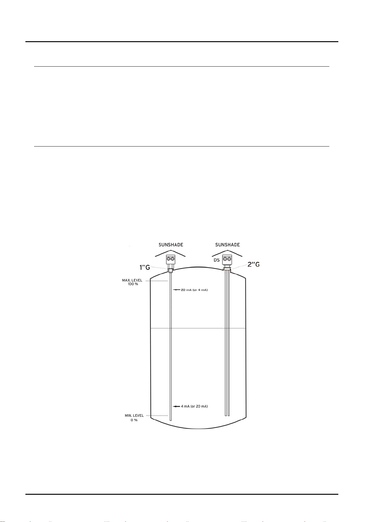
The output current signal is 4 to 20 mA. These values can be sited where we want
in the probe.
DT0305 Page 3
Page 4
NMC
6. Current simulation
Using this option the NMC generates in the supply loop, a 4 to 20 mA current, in
steps of 1 mA. This function is very useful to make tests with independence of the
level of the tank.
7. Installation
The NMC is installed using a G1” (G2” in DS version).
The probe must be installed avoiding a good contact between the probe and the
tank’s wall.
Electronic of the NMC unit should be protected with shelter against development of
too high temperature by direct sunshine.
Be ensured that the connection to the tank has been done properly. The NMC ’s
thread should not been forced.
The electrical connection between the thread and the tank has to be good.
Páge 4 DT0305
Page 5
NMC
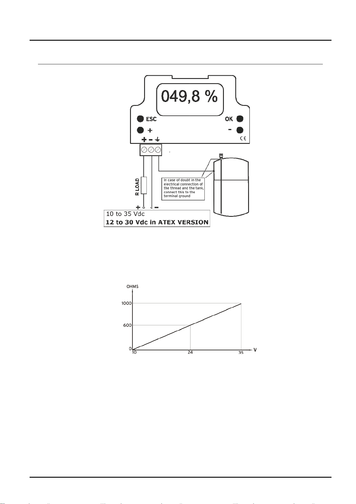
8. Electrical connection
The maximum resistance of the line in serial depends on the power supply. These
values have to be bear in mind for the good run of the NMC.
DT0305 Page 5
Page 6

NMC
9. Programming
9.1 Calibrating probe
Calib.Probe OK
Output +
Language Back ESC
CALIBRATION
¿SURE?
YesOK NoESC
CALIBRATION
Low Level OK
High Level +
LOW LEVEL ADJUST
Enter the actual level in probe.
+And-: 010.0 % OK
Calibrating
PROBE
For low level
….WAIT….
***PROBE
CALIBRATED**
Calib.Probe OK
Output +
Language -
Back ESC
1. Pressing any key, you enter in the main menú.
Press (OK) to enter in calibration probe.
2. To avoid mistakes, asks again if you are sure that
you want to calibrate the unit. Press (OK) another
time to enter.
3. If the level in the tank is low, we will choose the
(OK) option to adjust the unit with the lowest level
4. If, for example, when you adjust the low level, the
level of the tank is the 10 % of the capacitance, we
will indicate it in the display using the ( + ) and ( - )
keys. Confirm with ( OK ).
5. In this moment the microprocessor makes the
operations to choose the best measurement range.
This operations takes some seconds.
6. When this operation is finished, the display shows
the message “PROBE CALIBRATED”.
7. Automatically the display shows the main menu.
Now need calibrate the High Level, then pressing
(OK) another time to enter in the calibration probe
menu.
Páge 6 DT0305
Page 7

NMC
CALIBRATION
¿SURE?
Yes OK No ESC
CALIBRATION
Low Level OK
High Level +
HIGH LEVEL ADJUST
Enter the actual level
In probe
+ and - :080.0 % OK
Calibrating
PROBE
For low level
…. WAIT ….
*** PROBE
CALIBRATED ***
Calib.Probe OK
Output +
Language Back ESC
8. To avoid mistakes, asks again if you are sure that
you want to calibrate the unit. Press ( OK ) another
time to enter.
9. Pressing (+) we enter in High level calibration.
10. If when you adjust the high level, the liquid in the
tank is 80 % of the capacitance, we will indicate it in
the display using the (+) and (-) keys. Confirm with
(OK).
11. The microprocessor makes the operations to
calibrate the maximum level of the unit. This
operation takes some seconds.
12. The display shows this message to indicate NMC
has finished the calibration internal process.
When the liquid level will be in the minimum point, it
will indicate 000.0 % and when the liquid level will
be in the maximum, 100.0 %.
13. Automatically, the display shows the main menu.
Pressing ESC the unit returns to read state.
Pressing (+) we can enter in output adjustment
menu and simulation mode.
9.2 Output Adjustment
Calib.Probe OK
Output +
Language Back ESC
OUTPUT
Output SIM -
Output Adj +
Back ESC
DT0305 Page 7
1. Pressing any key, you enter in the main menu.
Press (+) to enter in Output.
2. Pressing (+), we enter in Output adjustment menu.
Page 8

NMC
¿Where do you want the 4
¿Where do you want the 20
+ and - : 1 OK
Output SIM -
Output Adj +
Back ESC
OUTPUT ADJUST
mA output?
+ and - : 005.0 % OK
OUTPUT ADJUST
mA output?
+ and - : 095.0 % OK
MEASURE FILTER
Enter filter’s level
0 to 5
OUTPUT
049.8%
12.04 mA
3. This asks, where do you want the NMC gives us 4
mA. If you want it in 5 % of the probe. Using (+) and
(-) we indicate this value in the display. Confirm with
(OK)
4. We do the same for the 20 mA. In this case, if we
want this current in the 95 % of the probe, we will
indicate this value using (+) and (-).
Confirm with (OK)
5. Finished the adjustment, we can incorporate a filter
to avoid oscillations caused by quick movements of
the liquid’s surface. This value between 0 and 5
(maximum filter). Confirm with (OK)
6. Automatically return to output menu.
Pressing ESC return to measuring mode.
7. In this point, the NMC is adjusted. The number in
% indicates the height that reaches the level in the
probe (0 to 100). The value of the current will
depends f the adjustment of the points 3 and 4 of this
section, and it can be in any point of the probe. It
can be in maximum point and in the 20 mA at the
minimum.
9.3 Output simulate
Calib.Probe OK
Output +
Language Back ESC
OUTPUT
Output SIM -
Output Adj +
Back ESC
Páge 8 DT0305
1. Pressing any key, you enter in the main menu.
Press (+) to enter in Output.
2. Pressing (-), we enter in simulate output menu.
Page 9

NMC
SIMULATE OUTPUT
Back ESC
+ and - : 04 mA OK
9.4 Language
Calib.Probe OK
Output +
Language Back ESC
LANGUAGE
+&- : English OK
3. In this screen, using the (+) and (-) keys, the loop
current (2 wire) will change in steps of 1mA. With this
option, you can do current testes without generator.
Pressing (OK) returns to menu show in point 2.
Pressing (ESC) returns to read mode.
1. Pressing any key, you enter in the main menu.
Press (-) to enter in Language.
2. Pressing (+) or (-) we can choose the language for
the display.
Language available: Spanish, English, German,
Italian, French, Portuguese and Catalan.
Pressing (OK) return to main menu in language
selected.
DT0305 Page 9
Page 10

NMC
10. Technical Data
Note: Kobold Mesura makes every attempt to ensure the accuracy of these
specifications but reserves the right to change them at any time.
Measuring principle: Capacitive (for liquids up to 1000 pF)
Probe length: 265…4000 mm (shorter versions on request)
Accuracy: ±2 mm
Medium temp.: max. 90 ºC, NMC-H max.125 ºC
Max. pressure: 30 bar at 20 ºC, 10 bar at 90 ºC
Media DC-value: ε
Materials: Housing: Polycarbonate
Connection: St.steel 1.4305 (NMC-N,NMC-T,NMC-H)
PVDF (NMC-S)
Probe: - St.steel with PTFE coating (NMC-N, NMC-T)
- PVDF coating (NMC-S)
- St.steel probe 1.4305 with internal sensor
(st.steel with PTFE coating) (NMC-T)
Mech.Connection: G1 male (NMC-N,NMC-H,NMC-T)
G2 male (NMC-S)
Supply voltage: 10…35 Vdc
12…30 Vdc for ATEX
Electr.connection: via 1 (2) cable gland M20
Output: 4-20mA, two wire
Protection: IP 65
= min. 1.5
r
ATEX Ex II 2/1 GD Ex ia IIC T4 Gb/Ga
Ex ia IIIC T85ºC Db/Da
-20ºC<Ta<+60ºC
Páge 10 DT0305
Page 11

NMC
11. Safety Instructions (ATEX)
11.1 Validity
These safety instructions must be applied to the capacitive level transmitters series
NMC...E when used in explosive atmospheres.
11.2 General considerations
Working principle of NMC..E is capacitive and these instruments are used to
measure and control the level on a liquid of any zone. Including zones with
explosion risk.
Level instruments NMC..E have an analogue output 4-20 mA two wires, and are
used to measure the level in a tank. They can be used in explosive atmospheres
group IIA, category 1/2GD
NMC..E have a housing with the electronic module and a probe that can be rigid
(one or two roads) or flexible.
The probe can be installed in explosion risk areas 1/2GD.
The process connection element and the housing must be installed in area 2GD.
When installing these instruments in explosive zones, all general instructions and
recommendations regarding installations in explosive zones, as well as the
instructions of this safety manual must be followed.
Verify that all data in the label of the instrument fits the installation requirements.
EN60079-0, EN60079-11, EN60079-26, EN60079-31 must be followed.
Switch off power supply before open housing or be sure there is no explosion risk.
Verify that housing is closed before switch on the instrument.
It is very important to verify that ground terminal of the instrument is connected to
ground of the installation.
Installation in hazardous zones must be done by trained people.
11.3 Protection against ESD (electro static discharges)
Instruments with plastic parts that can produce electro static discharges, have a
label for it.
It is important to follow some rules to avoid ESD:
-Avoid frictions.
-Do not clean the instrument with a dry cloth.
-Do not install in locations close to pneumatic flow of materials or close to steam
exhaust systems.
11.4 Chemical resistance
Materials in touch with the instrument must be chemically resistant specially when
used in hazardous zones category 1/2GD.
DT0305 Page 11
Page 12

NMC
12. Installation in classified zone (ATEX)
In classified zones, NMC EX version, must
be installed with the housing in zone 21, 22
dust and 1, 2 for Gas (category 2) or NOT
CLASSIFIED.
Process connection is mounted in the border
wall between areas of category 2 and 1.
Probe can be mounted in ZONE 20,21 or 0,1
(category 1).
Installation must be done by people trained
in ATEX environments.
13. Label Description (ATEX)
Páge 12 DT0305
Page 13

NMC
14. Declaration of conformance ATEX
DT0164
DECLARACIÓN DE CONFORMIDAD EU
EU DECLARATION OF CONFORMITY
EU-KONFOMITÄTSERKLÄRUNG
DÉCLARATION DE CONFORMITÉ
DICHIARAZIONE DI CONFORMITÀ EU
KOBOLD MESURA SLU
Avda. Conflent 68, nave 15 08915 Badalona (España)
Declara, bajo la propia responsabilidad, que el producto
Declares under our sole responsibility, that the product
Erklärt in alleiniger Verantwortung, dass das produkt
Déclare sous sa seule responsabilité, que le produit
Dichiara sotto la propia responsabilità, che il prodotto
NMC…E
A los cuales se refiere esta declaración, son conformes a las siguiente Directivas Europeas:
To which this declaration relates is in conformity with the following European Directives:
Mit folgenden Richtlinien konform ist:
À auxquels se réfère cette déclaration, ils sont conformes aux Directives Européennes suivant :
A ai quali si riferisce questa dichiarazione, sono conformi alle direttive europee seguente:
EMC2014/30/EU LVD2014/35/EU Atex2014/34/EU RoHS2011/65/EU
Normas armonizadas y documentos de la normativa aplicados:
Applied harmonised standards and normative documents:
Angewandte harmonisierte Normen und normative Dokumente:
Normes harmonisées et documents normatifs appliqués
Norme armonizzate e documenti normativi applicati:
EN61010-1 :2011 EN60079-0:2006 (acc. EN60079-0:2013)
EN61000-6-2 :2006 EN60079-26:2007 (acc. EN60079-26:2015)
EN60079-11:2007 (acc. EN60079-11:2013)
Certificado de examen CE de tipo
EC-type examination certificate Marking
EG-baumusterprübescheinigung Kennzeichnung
Attestation d´examen CE de type Inscription
Certificazione per esame di tipo CE Marcatura
Marcado
LOM07ATEX2032X
II 2/1 GD Ex ia IIC T4 Gb/Ga
Ex ia IIIC T85ºC Db/Da
-20ºC <
Ta < +60ºC
Fabricado en: KOBOLD MESURA SLU Avda. Conflent 68, nave 15 08915 BADALONA (Spain)
Made in:
Hergestellt in:
Fabriqué dans:
Fabbricato in:
Organismo notificado
Notified organism Number notification
Zertifizierungsstelle Zertifikatsnummer
Organization annoncée Nombre notification
Organismo informato Notifica di numero
: LOM 0163 Número notificación : LOM 05ATEX9070
Badalona june 2017 Gerente
DT0305 Page 13
Page 14

NMC
15. Declaration of conformance
DECLARACIÓN DE CONFORMIDAD EU
EU DECLARATION OF CONFORMITY
EU-KONFOMITÄTSERKLÄRUNG
DÉCLARATION DE CONFORMITÉ
DICHIARAZIONE DI CONFORMITÀ EU
KOBOLD MESURA SLU
Avda. Conflent, 68 nave 15 08915 Badalona (España)
Declara, bajo la propia responsabilidad, que el producto
Declares under our sole responsibility, that the product
Erklärt in alleiniger Verantwortung, dass das produkt
Déclare sous sa seule responsabilité, que le produit
Dichiara sotto la propia responsabilità, che il prodotto
NMC…
A los cuales se refiere esta declaración, son conformes a las siguiente Directivas Europeas:
To which this declaration relates is in conformity with the following European Directives:
Mit folgenden Richtlinien konform ist:
À auxquels se réfère cette déclaration, ils sont conformes aux Directives Européennes suivant :
A ai quali si riferisce questa dichiarazione, sono conformi alle direttive europee seguente:
EMC2014/30/EU LVD2014/35/EU RoHS2011/65/EU
Normas armonizadas y documentos de la normativa aplicados:
Applied harmonised standards and normative documents:
Angewandte harmonisierte Normen und normative Dokumente:
Normes harmonisées et documents normatifs appliqués
Norme armonizzate e documenti normativi applicati:
EN61010-1 :2011 EN61000-6-2 :2006
Fabricado en
Made in:
Hergestellt in:
Fabriqué dans:
Fabbricato in:
: KOBOLD MESURA SLU Avda. Conflent, 68 nave 15 08915 BADALONA (Spain)
Badalona June 2017 Gerente
DT0490
Páge 14 DT0305
Page 15

NMC
16. ATEX Certified
DT0305 Page 15
Page 16

NMC
Páge 16 DT0305
Page 17

NMC
DT0305 Page 17
Page 18

NMC
Páge 18 DT0305
Page 19

NMC
DT0305 Page 19
Page 20

NMC
17. Models
Páge 20 DT0305
Page 21

NMC
18. Order details
Version Probe length* Mechanical
ATEX Supply
connection
NMC-N
NMC-H
NMC-T
NMC-S 9G9 = G2, PVDF
…1 = up to 1 meter
…2 = up to 2 meter
…3 = up to 3 meter
….4 = up to 4 meter
2G6 = G1, st. steel
0 = without
E= ATEX
* Please specify in writing length.
3 = 10…35 Vdc
DT0305 Page 21
Page 22

NMC
19. Notes
Páge 22 DT0305
Page 23

NMC
DT0305 Page 23
Page 24

KOBOLD MESURA S.L.U
Avda Conflent Nº68 Nave 15
08915 Badalona
Tel.: +34 93 460 38 83
Fax: +34 93 460 38 76
E-Mail: info.es@kobold.com
www.kobold.com
Technical data
Subject to change without prior notice
 Loading...