

Page 1
Operating Instructions
for
Liquid Level Transducer
Model: NM-..
Page 2

NM
1. Contents
1. Contents........................................................................................................2
2. Note ..............................................................................................................3
3. Regulation Use .............................................................................................3
4. Operating Principle .......................................................................................4
5. Instrument Inspection....................................................................................5
6. Mechanical Connection.................................................................................5
7. Electrical Connection ....................................................................................6
7.1. General................................................................................................6
7.2. Level Sensors with remote Sensor......................................................6
7.3. Operation in explosion-hazardous zones 1 or 2 ..................................7
8. Technical Information....................................................................................8
9. Order Codes .................................................................................................8
10. Maintenance .................................................................................................9
11. Assistance in Case of Problems .................................................................10
Manufactured and sold by:
Kobold Messring GmbH
Nordring 22-24
D-65719 Hofheim
Tel.: +49(0)6192-2990
Fax: +49(0)6192-23398
E-Mail: info.de@kobold.com
Internet: www.kobold.com
page 2 NM 07/04
Page 3

2. Note
Please read these operating instructions before unpacking and putting the unit
into operation. Follow the instructions precisely as described herein.
The devices are only to be used, maintained and serviced by persons familiar
with these operating instructions and in accordance with local regulations
applying to Health & Safety and prevention of accidents.
When used in machines, the measuring unit should be used only when the
machines fulfil the EWG-machine guidelines.
3. Regulation Use
Kobold level transducers are used for the continuous level indication and level
control of all kinds of liquids. The simple design with only one moving part (the
float) allows for demanding applications where special reliability is demanded.
Kobold level transducers allow the continuous level indication and level control of
liquids unaffected by electrical conductivity, temperature, pressure or viscosity.
The level transducer may only be used in liquids that will assure free movement
of the float. The following points must be noted:
NM
• no large particles
• density of the fluid must not be less than that specified for the float type
• viscosity, pressure and temperature to be held within the limits given in the
technical specifications.
• no corrosive media
A variety of transducers in various designs, connecting configurations and
materials are available for the acquisition of the measuring values. The analogue
control instruments provide an electrical output signal which can be changed over
from 0-20 to 4-20 mA and stepless adjustable relay contacts for level control.
They may also contain integral level indicating circuitry (option RM).
NM 07/04 page 3
Page 4

NM
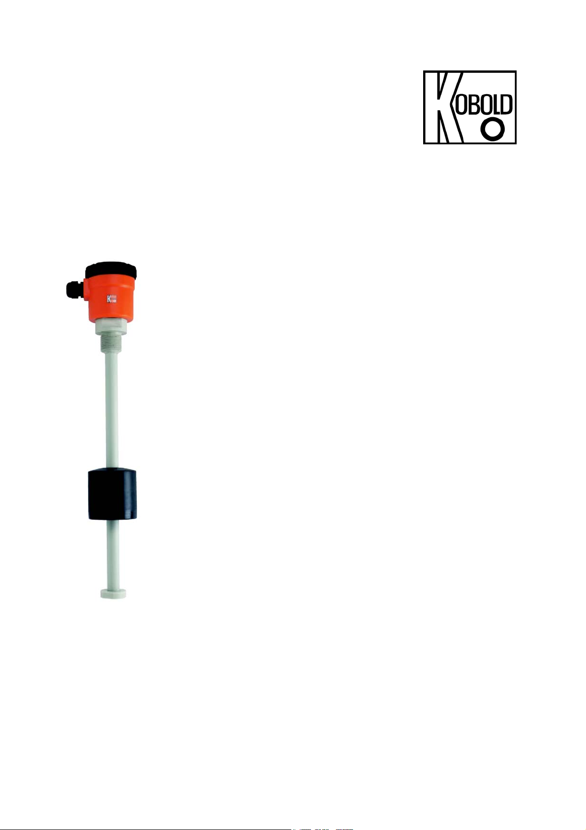
4. Operating Principle
The KOBOLD–Liquid Level Transducers
consist of a tube on which a float travels with
inserted magnet, similar to the Kobold level
float switch; however, in the NM, the magnet
remotely actuates the reed contacts inside the
tube.
The well-known principle of the level float
switch has been changed however, such that
the tube of the level transducer contains an
electric resistance chain and a reed contact
chain.
The float remotely actuates the contacts
through the tube wall and a voltage proportional
to the liquid level can be taken from the chain.
This voltage sensing corresponds to the
function of the slide of a resistance
potentiometer.
The sensed voltage is fed into a controller
which, depending on model chosen, generates
a current signal equivalent to the liquid level
(model DFM), additionally allows the control of
(2) adjustable alarms (model DST) or, in
addition to the above two functions, allows a
direct level indication (model DFA). Alternately,
with option “RM”, the unit outputs a 4-20mA
signal directly.
In order to meet the requirements for high
measuring and control accuracy, the electric
resistance chain is designed for measurement
in 10 mm increments up to an instrument
length of 2 m and in 20 mm increments for longer instruments.
page 4 NM 07/04
Page 5

5. Instrument Inspection
Instruments are inspected before shipping and sent out in perfect condition.
Should damage to a device be visible, we recommend a thorough inspection of
the delivery packaging. In case of damage, please inform your parcel service /
forwarding agent immediately, since they are responsible for damages during
transit.
Scope of delivery:
The standard delivery includes:
• Liquid Level Transducer, model: NM
• Operating Instructions
Caution: Heavy mechanical stress such as bending, impact or shock loads
to the level transducer could damage the transducer and/or the magnet.
NM
6. Mechanical Connection
The transducer has to be screwed into the flange, cap or the tank wall from the
outside or inside of the tank. For inside mounting the cable has to be routed
through the opening prior to mounting. Sealing of the connection threads should
be done with Teflon tape or similar. If the connection is not threaded the
transducer has to be inserted through a borehole and then secured with a
counter nut. Please pay close attention to correct sealing.
If the float has to be removed, pay attention to correct orientation when replacing
the float. The mark "TOP BI" indicates the top of the float.
NM 07/04 page 5
Page 6

NM
C
7. Electrical Connection
7.1. General
• Ensure that the supply wires are de-energized.
• To reduce the possibility of interference from other electric circuits the cables
should be wired separately.
• Please pay attention to the potentially detrimental operating conditions
regarding the placement of the cable.
• Connect the level transducer to the electronics in accordance with the
connection diagram below.
*Attention: The colours of the internal wires are only used for the internal wiring
and therefore only visible on level transducers with terminal box.
• When connecting the level transducer to the Kobold transmitters model DFA,
DST and DFM, please read the operating instructions of these units.
7.2. Level Sensors with remote Sensor
• Ensure that the electrical supply lines are powerless.
• To avoid faults caused by electrical fields from other circuits, the cables should
not be installed adjacent to other cables.
• Unscrew cover and run supply lines through cable gland.
• Connect the remote sensor to the electronics according to the wiring diagram
below.
-
-
16-32 V D
+
+
-
+
page 6 NM 07/04
Page 7

7.3. Operation in explosion-hazardous zones 1 or 2
For operation of the level transducer in hazardous zones 1 or 2, two safety
barriers to separate the intrinsically safe and non-intrinsically safe circuits must
be installed in the transducer circuit. This is possible only for special level
transducers with a total internal resistance of 40 kΩ.
NM
NM 07/04 page 7
Page 8

NM
8. Technical Information
Control voltage: max. 24 V
Control current: max. 0,1 A
Hysteresis: approx. half of resolution
Total resistance: approx. 5 kΩ (intrinsically safe: approx.
40 kΩ)
Model Resolution
NM-298... 15 mm -20..+130 °C 15 bar min. 0,87 g/cm³
NM-299... 15 mm -20..+130 °C 15 bar min. 0,72 g/cm³
NM-310...PVC
NM-320...PPH
NM-301...
NM-302...
NM-318...(PVC)
NM-328...(PPH)
NM-338...(PTFE)
10 mm
(20 mm > 2 m)
10 mm
[20 mm > 2 m)
10 mm
(20 mm > 2 m)
10 mm
(20 mm > 2 m)
10 mm
(20 mm > 2 m)
10 mm
(20 mm > 2 m)
10 mm
(20 mm > 2 m)
Temperature
of media
-20..+60 °C 6 bar min. 0,72 g/cm³
-20..+90 °C 6 bar min. 0,72 g/cm³
-20..+130 °C
-20..+130 °C
-20..+60 °C 6 bar min. 0,6 g/cm³
-20..+90 °C 6 bar min. 0,59g/cm³
-20..+130 °C 6 bar min. 0,79 g/cm³
Max. operating pressure Density of
media
15 bar
(depending on flange)
15 bar (depending on
flange)
min. 0,8 g/cm³
min. 0,8 g/cm³
9. Order Codes
Mechanical connection Model Elecctrical connection Resistance
G 3/8 NM-298 R10...
G 1 ½ NM-302 R40...
Flange DN 50 PN 10 NM-302 F50...
Flange DN 65 PN 10 NM-302 F65...
Flange DN 80 PN 10 NM-302 F80...
Flange DN 100 PN 10 NM-302 F1H...
Please specify measuring length “L” and cable length in writing.
page 8 NM 07/04
...S= Silicone cable
...Y= special connection
...R= connection box
...M= with transmitter
...Y= special connection
...0= 5 kΩ
...E= 40 kΩ
Page 9

Mechanical connection Model Electrical connection Resistance
...C = PVC cable
G ½ NM-299 R15...
G ½ NM-301 R15...
Flange DN 100 PN 10 NM-301 F1H...
Please specify measuring length “L” and cable length in writing.
...S = silicone cable
...Y = special connection
...R = connection box
...M = with transmitter
...Y = special connection
...0= 5 kΩ
...E= 40 kΩ
Mechanical connection Model Electrical connection Resistance
G2/ PVC NM-310 R50...
G2/ PPH
Flange DN 65/ PVC
Flange DN 65/ PPH NM-320 F65...
Please specify measuring length “L” and cable length in writing.
NM-320 R50...
NM-310 F65...
...R= connection box
...M= with transmitter
...Y= special connection
...0= 5 kΩ
...0= 40 kΩ
NM
Mechanical connection/
Model Electrical connection Resistance
material
G1/ PVC NM-318 R25...
Flange DN 80 PN 10/ PVC NM-318 F80...
G 1/ PPH NM-328 R25...
Flange DN 80 PN 10/ PPH NM-328 F80...
G 1/ PTFE NM-338 R25...
Flange DN 80 PN 10/ PTFE NM-338 F80...
Please specify measuring length “L” in writing.
...R= connection box
...M= with transmitter
...Y= special connection
10. Maintenance
The level transducer requires no maintenance. The tube and float should
occasionally be inspected for deposits or corrosion, and should be cleaned from
time to time.
...0= 5 kΩ
...0= 40 kΩ
NM 07/04 page 9
Page 10

NM
11. Assistance in Case of Problems
page 10 NM 07/04
 Loading...