

Page 1
Operating instructions
for
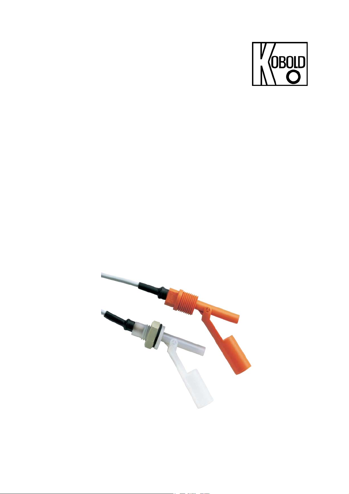
Plastic Level Switch for Liquids
Model: NKP
Page 2

NKP
1. Contents
1. Contents........................................................................................................2
2. Note ..............................................................................................................3
3. Instrument Inspection....................................................................................3
3. Regulation Use .............................................................................................3
4. Operating Principle .......................................................................................4
5. Instrument Inspection....................................................................................4
6. Mechanical Connection.................................................................................4
7. Electrical Connection ....................................................................................5
8. Technical Information....................................................................................6
9. Order Codes .................................................................................................7
10. Dimensions ...................................................................................................7
11. Declaration of Conformance .........................................................................8
Manufactured and sold by:
Kobold Messring GmbH
Nordring 22-24
D-65719 Hofheim/Germany
Tel.: +49 (0)6192-2990
Fax: +49(0)6192-23398
E-mail: info.de@kobold.com
Internet: www.kobold.com
Seite 2 NKP 11/04
Page 3

2. Note
Please read these operating instructions before unpacking and putting the unit
into operation. Follow the instructions precisely as described herein.
The devices are only to be used, maintained and serviced by persons familiar
with these operating instructions and in accordance with local regulations
applying to Health & Safety and prevention of accidents.
By usage in machines, the measuring unit should be used only when the
machines fulfil the EWG-machine guidelines.
3. Instrument Inspection
Instruments are inspected before shipping and sent out in perfect condition.
Should the damage to a device be visible, we recommend a thorough inspection
of the delivery packing. In case of damage, please inform your parcel service/
forwarding agent immediately, since they are responsible for damages during
transit.
NKP
Scope of supply:
• Plastic Level switch, model: NKP
• Operating instructions
4. Regulation Use
Model NKP devices are for use when monitoring liquid levels. The device should
only be used with liquids that are compatible with the unit’s materials of
construction. Level control is often accomplished with at least two level switches one acting to sense the minimum level and the other for maximum level
detection.
NKP 11/04 Seite 3
Page 4

NKP
5. Operating Principle
The plastic level switch NKP is designed for economical control of liquids in
vessels. Many industrial applications can be realized with two different plastic
versions each with three different mountings. The switch is remarkable for its
maintenance-free design, small dimensions and reed contacts with high switch
capacity. The switch is mounted on the side of the vessel. A hinged plastic float
with a magnet floats up and down through the liquid level. The encapsulated reed
contact is operated by the magnet. The switching function (N/O contact/N/C
contact) is determined by the installation position. The switching function is
reserved by simply rotating the switch through 180 °C.
6. Mechanical Connection
The level switch should be mounted so that the float can move freely over its
entire path without hitting the walls, floor or roof of the container. Avoid fitting the
switch where agitators or inlet valves could expose it to excessive turbulence.
Make sure that the medium does not contain solids or ferrite particles, as they
could collect on the float magnet and interfere with the switching operation. If the
liquid does contain sediment or suspended matter, you must be sure they do not
come into contact with the float system.
4 Nm of torque should be applied to the mounting nut for the NKP-6
Mount the switch so that it is easily accessible for installation and maintenance.
• Make sure that the allowed max. process pressures and service temperature
for the device are not exceeded.
• Mount the unit on a horizontal axis.
• Check that the joints are tight, immediately after installation.
Seite 4 NKP 11/04
Page 5

Mounting position
The mounting position of the level switch determines the contact operation.
NKP
7. Electrical Connection
Attention! Be sure that the supply voltage of your system is the same as
that specified on the device nameplate.
• Before proceeding, be sure that the electrical supply lines are de-energised.
• Attach the connection cable to your system, as indicated in the diagram below.
• The level switch is totally insulated; a protective grounding conductor is not
required.
NKP 11/04 Seite 5
Page 6

NKP
r
Conductor colour code
N/O contact
b
The device is ready for operation once you have connected your own process
devices.
bl
8. Technical Information
Switch housing: NKP-14.., -24.., -64..: polypropylene
NKP-15.., -25.., -65..: PVDF
Connections: NKP-1..: G 1/2
NKP-2..: 1/2" NPT
NKP-6..: M 16
Float: NKP-14.., -24.., -64..: polypropylene
NKP-15.., -25.., -65..: PVDF
Seal: NKP-6401: NBR
NKP-6501: FPM (FPM)
alternative: EPDM
Max. temperature: NKP-14.., NKP-24.., NKP-64..: 80 °C
NKP-15.., NKP-25.., NKP-65..: 100 °C
Max. pressure: 10 bar
Installation position: horizontal (±30 ° from the horizontal plane)
Contact components: N/O contact /N/C contact (depending on the
Installation)
Electrical connection: stranded cable AWG20, 2-core, PVC, 1 m
Switch capacity: max. 230 VAC/VDC /
max. 40 VA / 2 A
Contact resistance: max. 80 mΩ
Min. electric streng: 400 VDC/ 1 s
Medium density: NKP-14.., -24.., -64..: > 0.6 g/cm³
NKP-15.., -25.., -65..: > 0.95 g/cm³
Protection: IP 68
Seite 6 NKP 11/04
Page 7

9. Order Codes
Example (NKP-1401)
Model Connection Housing Cable
1 = G ½
NKP-
* Please specify in wiriting.
2 = ½ NPT
6 = M 16
10. Dimensions
401 = polypropylene
501 = PVDF
NKP
1 = 1 m PVC cable
1,6 = 1,6 m PVC cable
3 = 3 m PVC cable
Y = special length*
NKP 11/04 Seite 7
Page 8

NKP
11. Declaration of Conformance
We, KOBOLD-Messring GmbH, Hofheim-Ts, Germany, declare under our sole
responsibility that the product:
Level switch model: NKP...
to which this declaration relates is in conformity with the standards noted below:
DIN EN 61010-1 2002-08
Safety requirements for electrical measuring, control and laboratory instruments
DIN EN 60529 2000-09
Protection type through housing (IP code)
in accordance with the general requirements of the guideline
Low voltage guideline 73/23 EEC
Hofheim, 06. Dec. 2002
H. Peters M. Wenzel
Seite 8 NKP 11/04
 Loading...