

Page 1

Operating instructions
for
Capacitive Level Monitor
NCW
Page 2

NCW
1. Content
1. Content ......................................................................................................... 2
2. Note .............................................................................................................. 3
3. Instruments Inspection .................................................................................. 3
4. Description .................................................................................................... 3
5. Regulation Use .............................................................................................. 3
6. Operating principle ........................................................................................ 4
7. Mechanical connection .................................................................................. 4
8. Electrical connection ..................................................................................... 5
9. Adjustment .................................................................................................... 6
10.Models .......................................................................................................... 9
11.Technical Data ............................................................................................ 10
12.EU Declaration of conformance .................................................................. 11
13.Notes ........................................................................................................... 12
Manufactured by:
9.1 Module replacement ............................................................................ 8
Kobold Mesura S.L.U
Avda Conflent Nº68 Nave 15
08915 Badalona
Tel.: +34 93 460 38 83
Fax: +34 93 460 38 76
E-Mail: [email protected]
Internet: www.kobold.com
Edition: May 2017
Page 2 DT0453
Page 3

NCW
2. Note
Please read these operating instructions before unpacking and putting the unit in
operation. Follow the instructions precisely as described herein.
The devices are only to be used, maintained and serviced by persons familiar with
these operating instructions and in accordance with local regulations applying to
Health & Safety and prevention of accidents.
3. Instruments Inspection
Instruments are inspected before shipping and sent out in perfect condition.
Scope of delivery
The standard delivery includes:
Capacitive Level Monitor NCW
Cable gland M20
Operating Instructions
4. Description
All NCW level switch instruments can be used in any application where one level of
liquid in a tank or a silo must be detected
5. Regulation Use
The capacitive Level Monitor is indicated to punctual level detection in tanks
containing liquids.
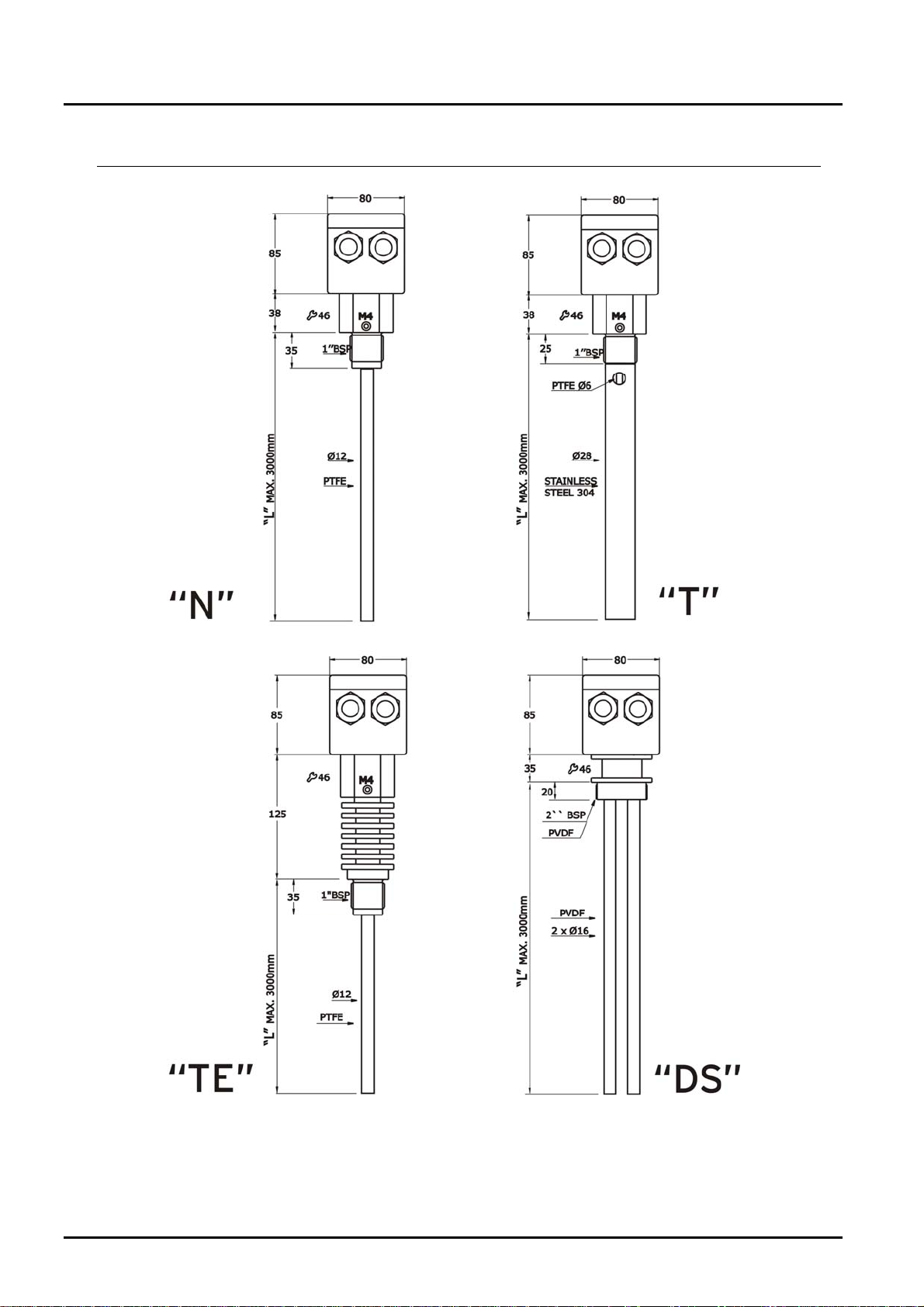
The are 4 basic models:
NCW-N: Rigid probe in PTFE, for general applications in metallic tanks.
NCW-T: Rigid probe in PTFE with stainless steel tube (ground tube). For products
with a low dielectrical constant and non metallic tanks.
NCW-H: Rigid probe in PTFE with special thread made of stainless steel for high
Temperatures (125ºC)
NCW-S: Double rigid probe in PVDF for NON METALLIC tanks containing
aggressive liquids that attack stainless steel.
DT0453 Page 3
Page 4
NCW
6. Operating principle
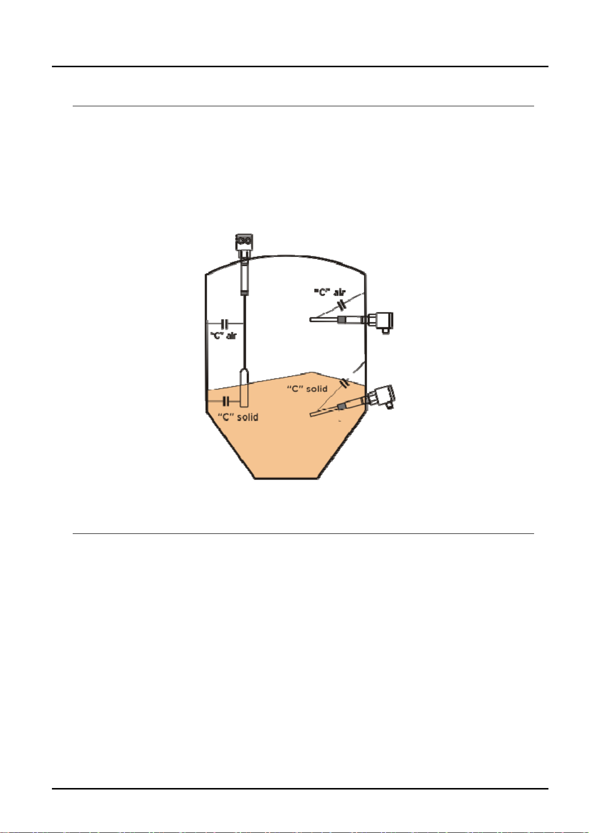
The NCW sensor together with the wall of the tank is a capacitor.
The dielectric constant of this capacitor is the air when the product (media) doesn’t
reach the sensor. When the product covers the sensor, the dielectric constant is the
product one. The electronic circuit of the NCW detects this change and activates an
output relay.
7. Mechanical connection
Before installation:
Remove all packing materials and transport retainers and ensure that no
such materials remain in the device.
Make sure that the permitted max. operational pressure and temperature
limits are not exceeded (see Technical Information)
Protect the measuring sensor from external damage.
The units may not be installed at a location within an inductive field.
If possible, check directly after mechanical installation whether the
connection thread to the pipe is fully sealed.
Installation:
The NCW is installed using a 1”BSP, (2”BSP Thread in NCW-S version)
Check if probe’s length is correct to detect the level. At the end of the probe there
is a stopper to guaranty the electrode waterlight.
This part (10mm aprox.) is not sensible to the liquid.
Page 4 DT0453
Page 5

NCW
8. Electrical connection
DT0453 Page 5
Page 6
NCW
VERY IMPORTANT
Be sure that power supply corresponds with the indicated in the equipment’s
label.
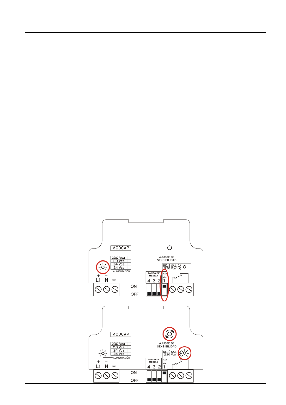
GREEN led lighting indicates that equipment is powered
RED led lighting indicates that output relay is activated.
Using SELECTOR 1, you can choose relay operation NO or NC when the product
covers te probe.
Protection fuse of 0.5mA must be put in serial with supply line.
Ground terminal is internally tied to the connection thread.
Be sure that ground line has same potential than ground of thank.
If you are not sure, please do not connect the ground terminal since the
instrument could be damaged.
9. Adjustment
After installation and connection verification, we proceed to AJUST SENSITIVITY to fit
the NCW with the tank and the product to measure.
Check that product doesn’t reach the probe. Power supply GREEN LED must be ON
1. Put DIP-SWITCH 1 to “MAX” position.
2. Turn the
“SENSITIVI
TY
ADJUSTM
ENT screw”
clockwise
until RED
LED lights.
Page 6 DT0453
Page 7
NCW
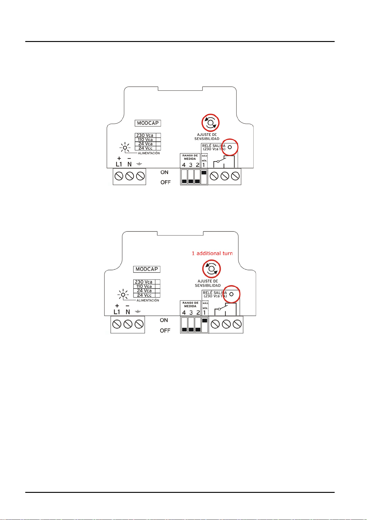
3. Turn slowly the “SENSITIVITY ADJUSTMENT screw” counter clockwise until
RED LED switches off.
4. Turn 360º more counter clockwise to avoid a critical adjustment. In case of
sticky products it is recommended to increase this adjustment.
The instrument is now adjusted. When product will reach the probe relay will be
activated and RED LED will light.
If we want the relay to work the REVERSE, put DIP-SWITCH 1 to “MIN”.
Check that no product remains on the probe when unloading the tank.
DT0453 Page 7
Page 8
NCW
9.1 Module replacement
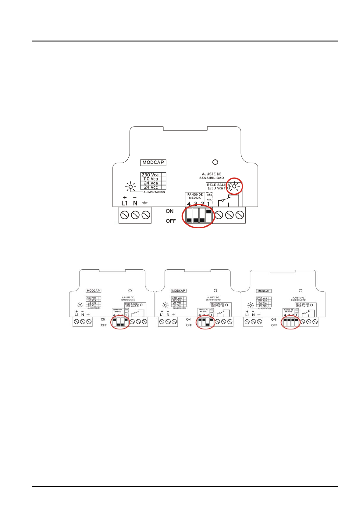
MODCAP modules are delivered with DIP-SWITCHES 2, 3 and 4 adjusted with its own
probe. In case of replacement, following procedure must be done with the probe free of
product:
1. With DIP-SWITCH 1 to “MAX” and 2, 3 and 4 to “MIN”, turn the multiturn
potentiomenter totally to clockwise (20 turns). RED LED will switch ON.
2. In case that RED LED doesn’t lights, move DIP-SWITCH 4 (drawing 1) to
ON. If RED LED still remains OFF, do same with DIP SWITCH 3 (drawing 2)
and finally with DIP-SWITCH 2 (drawing 3) until RED LED finally lights.
drawing 1 drawing 2 drawing 3
3. Once DIP-SWITCHES are correctly settled the SENSITIVITY ADJUSTMENT
must be done (chapter 8).
Page 8 DT0453
Page 9
NCW
10. Models
DT0453 Page 9
Page 10

NCW
11. T echnical Data
Note: Kobold Mesura makes every attempt to ensure the accuracy of these
specifications but reserves the right to change them at any time.
Supply: 24, 110, 230 Vac or 18 to 36 Vdc.
Max. Power: 1 VA
Process connection: 1G
Other connections: Flange DIN, clamp, etc.
Power supply and relay status LED.
Polycarbonate housing IP.65.
Ambient Temperature: -20…+60 ºC.
Process Temperature: max. 90ºC (125ºC model H).
Cable gland 2 x M20.
Relay Output: max. 250 Vca 1 A.
Sensitivity adjustment by multi-turn trimmer.
Vdc polarity reverse protection.
Minimum or maximum security adjustment.
Rod version probe covered with PTFE
Electromagnetic compatibility
EN 61010-1:2011 y EN61000-6-2:2006
Page 10 DT0453
Page 11

NCW
12. EU Declaration of conformance
DT0341
DECLARACIÓN DE CONFORMIDAD EU
EU DECLARATION OF CONFORMITY
EU-KONFOMITÄTSERKLÄRUNG
DÉCLARATION DE CONFORMITÉ EU
DICHIARAZIONE DI CONFORMITÀ EU
Ava. Conflent 68 nave 15, 08915 Badalona (España)
Declara, bajo la propia responsabilidad, que el producto
Declares under our sole responsibility, that the product
Erklärt in alleiniger Verantwortung, dass das produkt
Déclare sous sa seule responsabilité, que le produit
Dichiara sotto la propia responsabilità, che il prodotto
NCW...
A los cuales se refiere esta declaración, son conformes a las siguiente Directivas Europeas:
To which this declaration relates is in conformity with the following European Directives:
Mit folgenden Richtilinien Konform ist:
À auxquels se réfère cette déclaration, ils sont conformes aux Directives Européennes suivant :
A ai quali si riferisce questa dichiarazione, sono conformi alle direttive europee seguente:
EMC2014/30/EU LVD2014/35/EU RoHS2011/65/EU
Normas armonizadas y documentos de la normativa aplicados:
Applied harmonised standards and normative documents:
Angewandte harmonisierte Normen und normativer Dokumente:
Normes harmonisées et documents normatifs appliqués
Norme armonizzate e documenti normativi applicati:
EN61010-1:2011
EN61000-6-2:2006
Fabricado en
Made in:
Hergesteltlt in:
Fabriqué dans:
Fabbricato in:
Badalona 17 May 2017 Gerente
: KOBOLD MESURA SLU Avda. Conflent 68 nave 15, 08915 BADALONA (Spain)
KOBOLD MESURA S.L.U.
DT0453 Page 11
Page 12

NCW
13. Notes
Page 12 DT0453
Page 13

NCW
DT0453 Page 13
Page 14

NCW
Page 14 DT0453
Page 15

KOBOLD MESURA S.L.U
Avda Conflent Nº68 Nave 15
08915 Badalona
Tel.: +34 93 460 38 83
Fax: +34 93 460 38 76
E-Mail: [email protected]
www.kobold.com
Technical data
Subject to change without prior notice
 Loading...