

Page 1
KOBOLD Instruments Inc.
1801 Parkway View Drive
Kobold Instruments Canada Inc.
Pittsburgh, PA 15205
PH: 412-788-2830
FAX: 412-788-4890
www.koboldusa.com
9A Aviation
Point Claire, QC H9R 4Z2
PH: 514-428-8090
FAX: 514-428-8899
Precautions
Series NC
Liquid Level Switches
• User's Responsibility for Safety: KOBOLD manufactures a
wide range of process sensors and technologies. While each
of these technologies are designed to operate in a wide
variety of applications, it is the user's responsibility to select
a technology that is appropriate for the application, to install it
properly, to perform tests of the installed system, and to
maintain all components. The failure to do so could result in
property damage or serious injury.
• Proper Installation and Handling: Use a proper sealant
with all installations. Never overtighten the switch within its
fittings. Always check for leaks prior to system start-up.
• Wiring and Electrical: This is an electrically operated
device and only properly trained personnel should install and
maintain this product. Be sure that the voltage and current
supplied to the switch is within the recommended limits.
Electrical wiring should be performed in accordance with all
applicable national, state and local codes.
• Temperature and Pressure: The NC series float switch is
available in several material combinations. Temperature and
pressure maximums vary depending upon the material
selected. Consult the technical specifications for limits on a
particular model prior to installation. Operation outside these
limitations will cause damage to the unit and possible injury
to personnel.
Mechanical Installation:
• Material Compatibility: Make sure that the NC series
float switch is chemically compatible with the application
liquids. While the switch wiring is liquid resistant when
installed properly, it is not designed to be immersed.
The fitting should be mounted and sealed appropriately
so that the wiring does not normally come into contact
with fluid. Waterproof designs are possible on several
models. Use of the NC series float switches with
viscous, sticky or coating type liquids is not
recommended as float movement will be impeded.
Additionally, some solutions or mixtures may cause the
float to become inoperative if allowed to dry.
• Flammable, Explosive and Hazardous Applications:
The NC series switches (except for models NCS1074EX and NCS-7203) are not an explosion-proof
design. They should not be used in applications where
an explosion-proof design is required.
• Make a Fail-Safe System: Design a fail-safe system
that accommodates the possibility of switch or power
failure. In critical applications, KOBOLD recommends
the use of redundant backup systems and alarms in
addition to the primary system.
Electrical Installation:
Vertically Mounted Models:
Install with the float positioned vertically or up to a 30° inclination,
at top or bottom of the tank.
Switch logic is changed by removing the float retainer clip,
reversing (inverting) the float, and reinstalling the retainer clip.
Float differential (actuating/deactuating point) is approx. 1/8”.
Side-Mounted Models: NCS-5161 and NCB-5171:
Drill and deburr a 13/32” diameter hole for mounting.
Install with the float positioned vertically or up to a 30° inclination.
Switch logic is changed by: inverting the unit, or by removing the
float retainer clip, reversing (inverting) the float, and reinstalling
the retainer clip.
Side-Mounted Model: NCP-5094:
Drill and deburr a 1/2” diameter thru hole for mounting.
Install with the float positioned horizontally within 15° inclination.
Switch logic is changed by inverting the float switch assembly.
Switch Ratings Max Resistive Load
V.A. Volts
0-50 0.4 0.4
20
240 0.06 0.08
0-50 1.0 1.5
100
240 0.2 0.4
Switch Rating of UL Recognized Units: 20 VA
Plastic Stem: 50 - 240 VAC Pilot Duty
Metal Stem: 120 - 240 VAC Pilot Duty
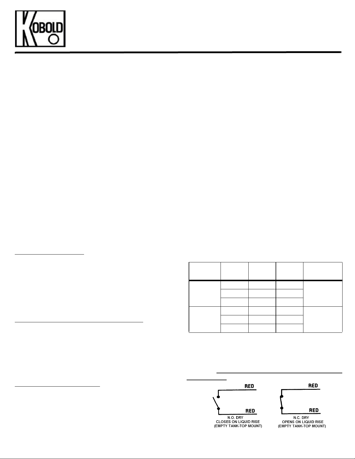
Wiring Diagram:
CAUTION: Contact protection is REQUIRED when switching
inductive loads. Consult KOBOLD for additional information.
Amps DCAmps ACAmps AC
Max.
1.0120 0.15 0.16
3.0120 0.4 0.8
FM Rev. 1/2/03
NC_manual_01-02-03
Page 2
IF THE FOLLOWING INSTRUCTIONS ARE NOT FOLLOWED, THE REED
Load
SWITCHES IN THIS DEVICE WILL BURN OUT!
This device incorporates reed switches which are used for sensing purposes and can only switch
very small loads (pilot duty service). They are not designed to directly switch solenoid valves,
motors and other high current devices.
When testing reed switches for operation only use an Ohmmeter and not a light.
Common accepted practice is to use an interface relay rated to handle the required electrical
load. In this way, the low current signal from the reed switch energizes the relay coil, which in turn
switches the larger load current.
PLEASE READ CAREFULLY!!
How to avoid damaging the reed switch:
TO PROTECT THE REED SWITCH AGAINST INDUCTIVE KICKBACK, EVEN IF THE RELAY
COIL CURRENT RATING IS WELL BELOW THE REED SWITCH RATING:
When a reed switch is used to drive external relays, voltage spikes can be generated at
coil activation.
If the source is an AC operated device, install a varistor (MOV), or Resistor/Capacitor Filter
across the relay coil.
If the source is a DC operated device, a general purpose diode ( IN 4004 ) placed across
the relay coil prevents electrical spikes. Connect the cathode (banded side) to the more
positive side of the coil.
AC Circuit Example
110 VAC
(Line)
Reed Switch
Pilot Duty
Relay
Coil
MOV or
RC Filter
Neutral
MOV Type: GE # V130 LA1
RC Filter Type: Paktron # 0.2uF/220 Ohm @400 V
Relay
Contact To
DC Circuit Example
Diode
1N4004
Reed Switch
Pilot Duty
+VDC
Relay
Coil
Relay
Contact To
- VDC
Page 3
KOBOLD Series NCG/NCM Multipoint Level Switches
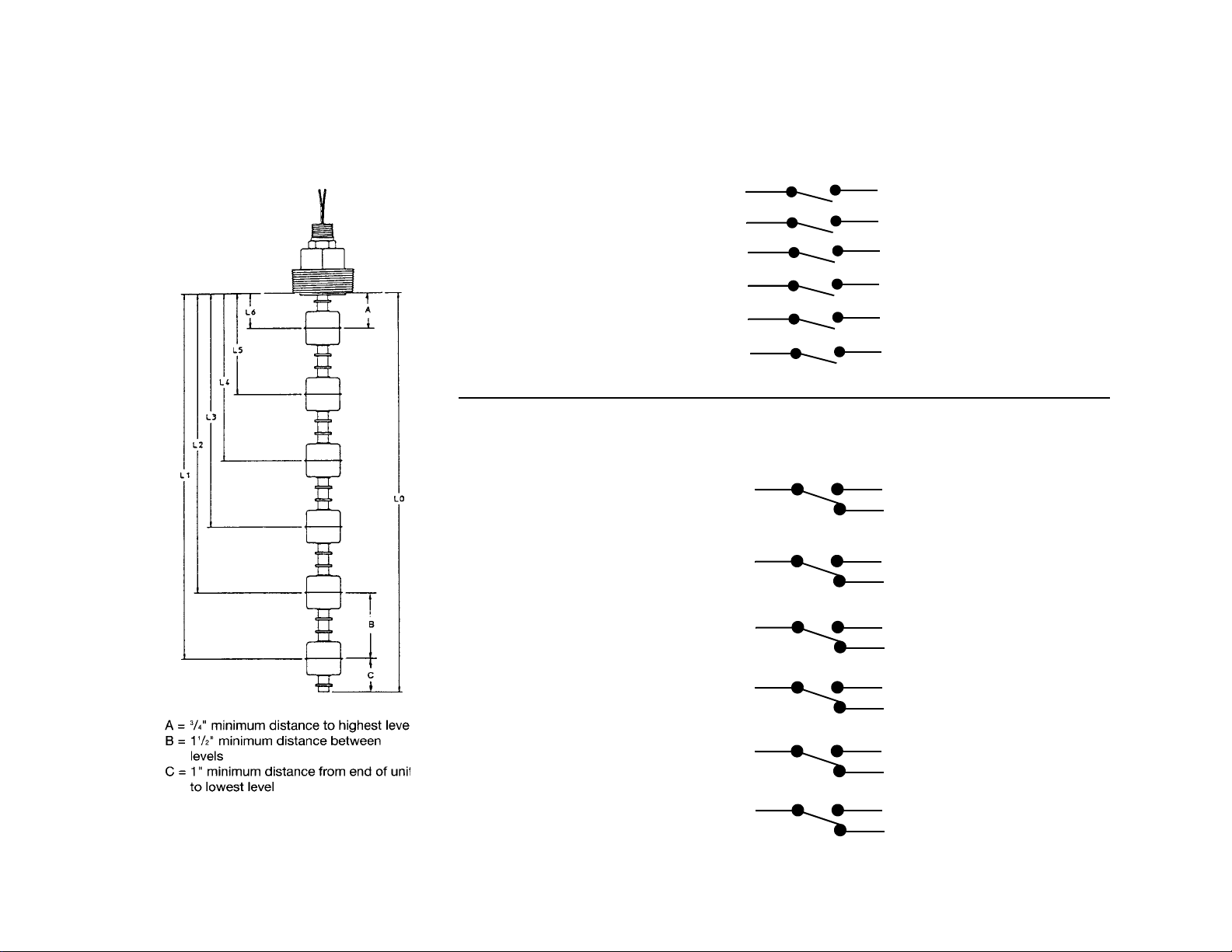
Wiring Diagram
SPST Switch Wiring
L6 Gray
L5 Orange
L4 Brown Brown
L3 Blue
L2 Yellow
L1 Red
Gray
Orange
Blue
Yellow
Red
SPDT Switch Wiring
L6 Gray
L5 Orange
L4 Brown
Wh/Gray
Wh/Blk/Gray
Wh/Orange
Wh/Blk/Orange
Wh/Brown
Wh/Blk/Brown
L3 Blue
L2 Yellow
L1 Red
Wh/Blue
Wh/Blk/Blue
Wh/Yellow
Wh/Blk/Yellow
Wh/Red
Wh/Blk/Red
Manual-NCG_8-01
FM Rev. 8/3/01
 Loading...