

Kobold NBK-R series, NBK-RM series, NBK-RT series, NBK-RA series, NBK-RT200 Operating Instructions Manual
...Page 1
Operating Instructions
for
Limit switch
Model: NBK-R
NBK-RM
NBK-RT
NBK-RA
Page 2

NBK-R...
page 2 NBK-R... K04/0617
1.Contents
1. Contents ........................................................................................................ 2
2. Note .............................................................................................................. 3
3. Instrument Inspection .................................................................................... 3
4. Regulation Use .............................................................................................. 3
4.1 Electrical limit switch ............................................................................ 4
5. Operating Principle ........................................................................................ 4
6. Mechanical Connection ................................................................................. 5
7. Electrical Connection .................................................................................... 6
8. Commissioning .............................................................................................. 7
9. Technical Information .................................................................................... 8
10.Order Codes ................................................................................................. 9
11.Illustrations .................................................................................................... 9
12.EU Declaration of Conformance .................................................................. 10
13.Type Examination Certificate ...................................................................... 11
Manufactured and sold by:
Kobold Messring GmbH
Nordring 22-24
D-65719 Hofheim
Tel.: +49 (0)6192-2990
Fax: +49(0)6192-23398
E-Mail: info.de@kobold.com
Internet: www.kobold.com
Page 3

NBK-R...
NBK-R... K04/0617 page 3
2.Note
Please read these operating instructions before unpacking and putting the unit
into operation. Follow the instructions precisely as described herein.
The devices are only to be used, maintained and serviced by persons familiar
with these operating instructions and in accordance with local regulations
applying to Health & Safety and prevention of accidents.
When used in machines, the measuring unit should be used only when the
machines fulfil the EC-machine guidelines.
3.Instrument Inspection
Instruments are inspected before shipping and sent out in perfect condition.
Should damage to a device be visible, we recommend a thorough inspection of
the delivery packaging. In case of damage, please inform your parcel service /
forwarding agent immediately, since they are responsible for damages during
transit.
Scope of delivery:
The standard delivery includes:
Electrical Limit Switches Model: NBK-R, NBK-RM, NBK-RT or NBK-RA
Operating Instructions
4.Regulation Use
Any use of the device which exceeds the manufacturer’s specification may
invalidate its warranty. Therefore, any resulting damage is not the responsibility of
the manufacturer. The user assumes all risk for such usage.
The Limit Switches for the NBK Bypass Level Indicators are used for continuos
measuring, display and monitoring of liquids in tanks or vessels. Depending on
the design the limit switches are suitable for applications with a higher operating
temperature or for the use in hazardous areas.
Page 4

NBK-R...
page 4 NBK-R... K04/0617
4.1 Electrical limit switch
- For standard applications NBK-R/NBK-RM: Bistable changeover contact fitted in
a polycarbonate housing with 3m connection cable
- For high temperature applications NBK-RT200/-RT400: Bistable changeover
contact fitted in an aluminium die cast housing with terminal connectors.
- For ATEX applications NBK-RA: Bistable changeover contact as an
encapsulated proximity switch fitted in metallic cast housing with 3 m connection
cable.
ATEX-marking for contact NBK-RA (encapsulated version):
II 2G Ex mb IIC T6 / T5 Gb
II 2D Ex mb IIIC IP67 T 105 °C Db
Use the contacts appropriate and as intended.
Make sure that only accessories are used in hazardous areas that meet
all the requirements of the European directives and national legislation.
The contacts NBK-RA with ATEX approval meet the requirements of category
2 GD. The proximity switches with ATEX approval are used in the following
zones:
2G in zone 1
3G in zone 2
2D in zone 21
3D in zone 22
5.Operating Principle
Kobold Bypass Limit Transmitter are used for the monitoring of limit values in
tanks or vessels.
They are firmly attached with mounting plates and ribbon clamps to the Bypass
Level Indicator, model NBK, and can be moved to any position on the bypasstube within the measuring length.
The reed-contacts in the limit switches react bistable and they are switched by
the magnetic float inside the NBK tube as passing by.
One or more limit switches can be mounted on the bypass.
Page 5
NBK-R...
NBK-R... K04/0617 page 5
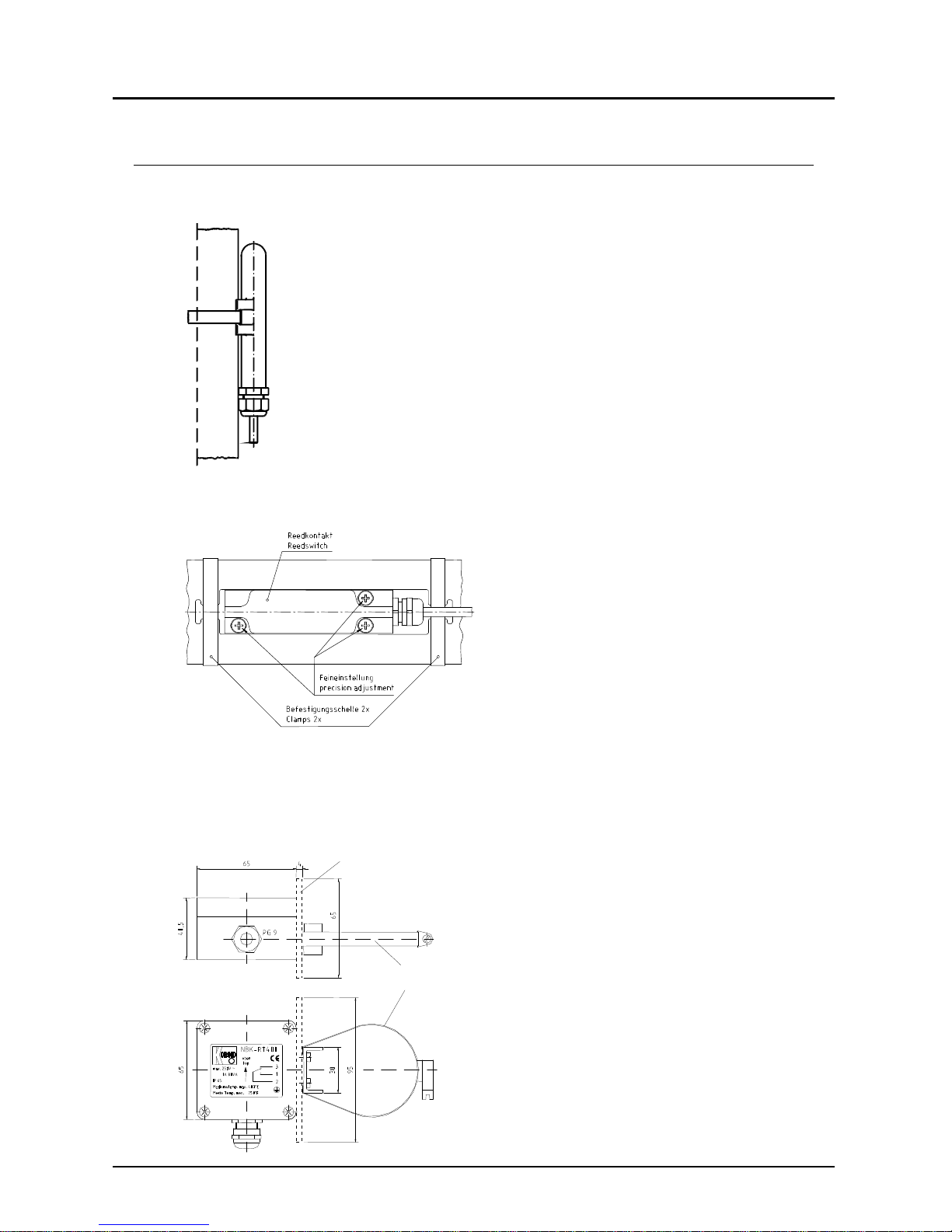
6.Mechanical Connection
NBK-R/NBK-RM
Mount and tighten the reed switch (NBK-R, NBK-RM
and NBK-RA) - if available - on the bypass tube at the
opposite side of the roller indicator with the provided
ribbon clamps (ex contact: two ribbon clamps). The height
of the switch contacts may be selected at will. The cable
connection must point downwards. The switch must be
attached close to the bypass tube. Due to technical
adaptations, it may come to malfunctions, when installing
new contacts in an existing plant. If the contact does not
switch during the float passes by, the preassembled
spacer (stainless steel) must be removed.
NBK-RA
NBK-RT200/400
The high temperature switch
RT200/400 will be mounted to the bypass
tube with the tube clip fixed at the contact
housing.
Th
ermal screening
(for 400°C-switch only)
Clamp
Page 6

NBK-R...
page 6 NBK-R... K04/0617
ATEX
- contact
brown
blue
black
1
3
2
blue
bl
ack
brown
Wit
h cable connection
Connect ion box
7.Electrical Connection
Limit switch NBK-R, NBK-RM, NBK-RT, NBK-RA
Attention!
Observe the allowed electrical ratings for the limit switch.
Maximum values
NBK-R
NBK-RM
Standard-
contact
NBK-RT
High
temperature
contact
NBK-RA
ATEX-contact
Switching capacity:
60 W/VA 80 VA 45 W/VA
Switching current:
1 A 1 A 0,6 A
Switching voltage:
230 V
AC/DC
250 V
AC/DC
230 V
AC/DC
Install the switch (if available) according to the
diagram and connect it to the electrical controller.
When switching inductive loads, such as contactors,
relays, etc., electrical limit values should not be
exceeded, also temporarily by e.g. voltage peaks.
The use of a contact protection relay is
recommended to avoid overloading the reed
contacts.
Valid regulations for hazardous areas, and
regulations for installation (DIN/VDE 0165), should
be observed when installing the NBK level indicator
in zone 1 or 2 of hazardous areas (no combustible
liquids).
Note to NBK-RT200:
The contact must be connected by an adequate
switch amplifier (e. g. REL-6005/-6010) to allow for
an ATEX-conform connection of the contact NBKRT-200 (see connecting example).
Note to NBK-RA:
Protect the circuit of the limit contact with a fuse.
This fuse must tolerate the permitted nominal
current of the switching contact and must have a
deactivating ability according to the possible short
circuit current of the power system at the place of
installation. The contact is activated by the North
Pole of a magnet and deactivated by its South Pole.
NBK-RA
NBK-R
NBK-RM
NBK-RT
Page 7

NBK-R...
NBK-R... K04/0617 page 7
Connecting example NBK-RT200 with a switch amplifier REL
to
clamp 1 or 3
to
clamp 2
1
2
3
NBK-RT200
Power supply unit acc.
IEC 60947-5-6
(e. g . REL-600x)
8. Commissioning
Commissioning of the electrical reed switch
Function of switches
All switches have three connection poles (black (2), blue (3) and brown (1)).
The black wire (2) is the common pole for both switching functions (N/C and N/O
contact).
The float must pass the switch once in both directions so that the switching function is in line with the terminal connection diagram and table below.
These instructions are often ignored when an alarm lamp is connected directly
with the result that the alarm lamp incorrectly indicates a fault.
When the switch has been passed, it is ready for operation and requires no
maintenance.
black (2) / blue (1) black (2) / brown (3)
float above open closed
float below closed open
Hysteresis
Hysteresis is the difference between contact closing
and opening points. A hysteresis of approximately 15
mm float travel is achieved by factory tuning of the
float magnet and contact strength.
Page 8

NBK-R...
page 8 NBK-R... K04/0617
9. T echnical Information
Limit contacts, model NBK-R/NBK-RM
Contact operation: bistable changeover contact
Switching hysteresis: approximately 15 mm
Max. switching capacity: 60 W/VA; 230 V
AC/DC
; 1 A
Contact resistance: 100 m
Medium temperature: max. 100 °C
Ambient temperature: max. 75 °C
Connection: 3 m PVC cable
Housing: polycarbonate
Protection: IP 67
Limit contacts, model, NBK-RT200/-RT400
Contact operation: bistable changeover contact
Switching hysteresis: approximately 15 mm
Max. switching capacity: 80 VA; 250 V; 1 A
Contact resistance: <20 m
Medium temperature: max. 200 °C (-RT200) / 400 °C (-RT 400)
Ambient temperature: 145 °C (RT200) / 350 °C (-RT400)
Connection: terminal connectors, screwed cable gland
Housing: aluminium die cast housing, terminal connectors
Protection: IP 65
ATEX limit switch, model NBK-RA
Contact operation: bistable changeover contact
encapsulated
Switching hysteresis: approximately 15 mm
Max. switching capacity: 45 VA, 230 V
AC/DC
, 0,6 A
Temperature class: T6 / T5
Max. medium temperature: 70 °C / 85 °C
Connection: 3 m PVC cable
Housing: metallic, cast (GD-ZN Al 4 Cu1)
Protection: IP 67
ATEX-marking: II 2G Ex mb IIC T6/T5 Gb
II 2D Ex mb IIIC IP67 T 105 °C Db
Page 9

NBK-R...
NBK-R... K04/0617 page 9
10. Order Codes
NBK-R
NBK-RM
Standard limit contact (bistable changeover contact)
NBK-RT200
High temperature limit contact, t
max
200 °C,
in conjunction with an external, intrinsically safe switch amplifier
as Simple Operator
NBK-RT400
High temperature limit contact, t
ma
x
400 °C
NBK-RA
ATEX-limit contact, encapsulated,
II 2G Ex mb IIC T6/T5 Gb
II 2D Ex mb IIIC IP67 T 105 °C Db
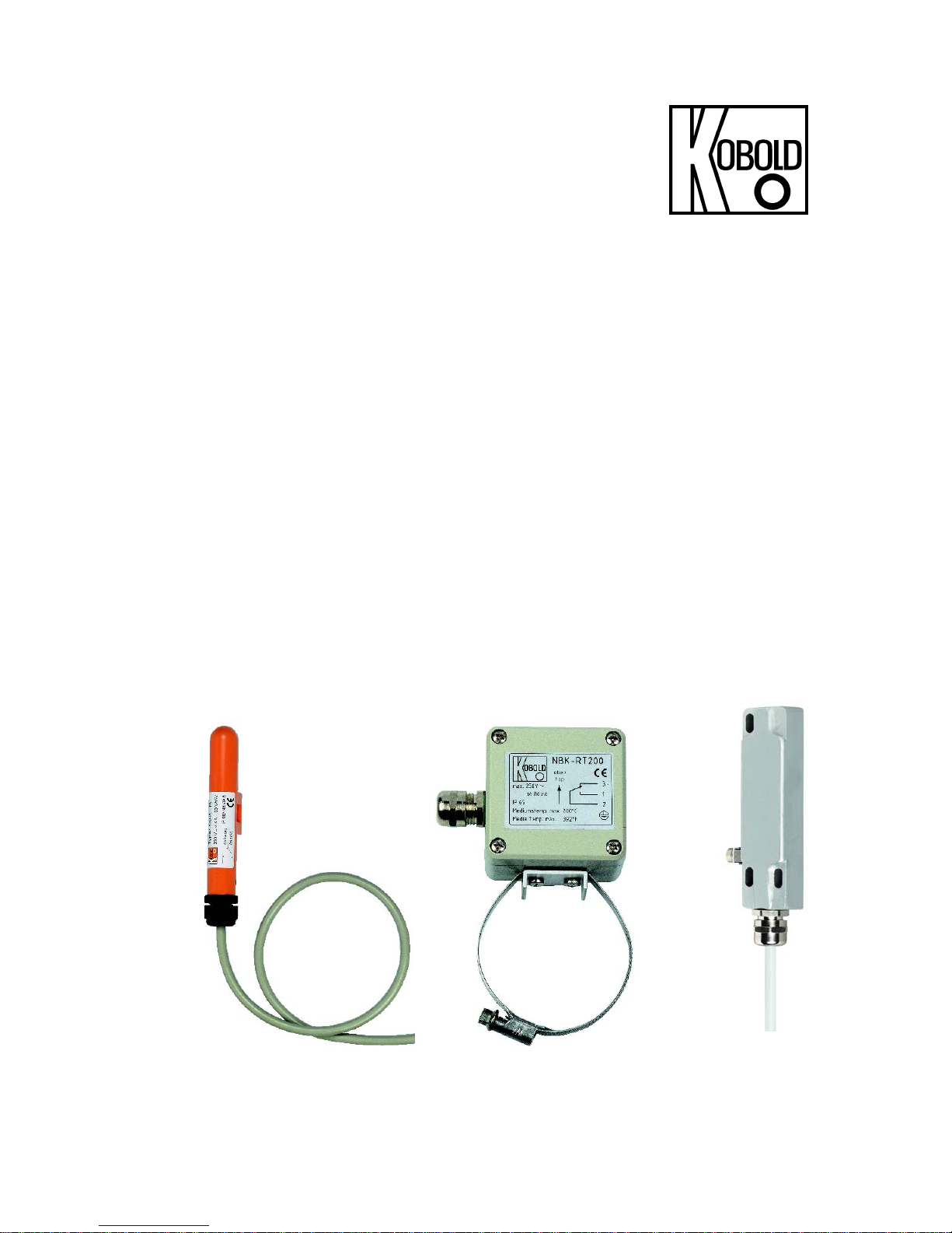
11. Illustrations
NBK-R/NBK-RM NBK-RT NBK-RA
Page 10

NBK-R...
page 10 NBK-R... K04/0617
12. EU Declaration of Conformance
We, KOBOLD Messring GmbH, Hofheim-Ts, Germany, declare under our sole
responsibility that the product:
Limit Contact model: NBK-R / NBK-RM / NBK-RT
to which this declaration relates is in conformity with the standards noted below:
DIN EN 61010-1: 2010
Safety requirements for electrical measuring, control and laboratory instruments
EN 60529:2014
Protection type through case (IP code)
Also the following EEC guidelines are fulfilled:
2014/35/EU Low Voltage Directive
2011/65/EU RoHS
Furthermore we declare that the product
model: NBK-RA (ELOBAU 610*)
to which this declaration relates is in conformity with the standards noted below:
EN 60079-0:2012 General Requirements
EN 60079-11:2012 Intrinsic Safety ‘i’
EN 60079-18:2009 Equipment protection by encapsulation ‘m’
EN 60079-26:2007 Equipment with equipment protection level (EPL) Ga
EC type examination test BVS 03 ATEX E 126 X
also the following EEC guidelines are fulfilled:
2014/34/EU ATEX
Hofheim, 28. June 2017
H. Peters M. Wenzel
General Manager Proxy Holder
Page 11

NBK-R...
NBK-R... K04/0617 page 11
13. Type Examination Certificate
Page 12

NBK-R...
page 12 NBK-R... K04/0617
Page 13

NBK-R...
NBK-R... K04/0617 page 13
Page 14

NBK-R...
page 14 NBK-R... K04/0617
Page 15

NBK-R...
NBK-R... K04/0617 page 15
Page 16

NBK-R...
page 16 NBK-R... K04/0617
 Loading...