

Page 1
Operating Instruction
for
Mini Bypass Level
Indicator
Model: NBK-M
Page 2

NBK-M
1. Contents
1. Contents ........................................................................................................ 2
2. Note .............................................................................................................. 3
3. Instrument Inspection .................................................................................... 3
4. Regulation Use .............................................................................................. 4
4.1. Bypass measuring tube system ........................................................... 4
4.2. Electrical limit switches (option) ........................................................... 4
4.3. Remote Sensor Reed Contact Chain of Resistors (option ..M.. / option
4.4. Remote sensor magnetostrictive sensor (option ..T..) ......................... 5
5. Operating Principles ...................................................................................... 5
6. Mechanical Connection ................................................................................. 6
7. Electrical Connection .................................................................................... 7
7.1. Switch (option) ..................................................................................... 7
7.2. Remote sensor Reed Contact Chain of Resistors (option ..W..) .......... 7
7.3. Remote Sensor: Chain of Resistors with 2-wire Transmitter (option
7.4. Remote Sensor: Magnetostrictive Sensor with 4-wire Transmitter
8. Commissioning .............................................................................................. 9
9. Trouble Shooting ......................................................................................... 10
10.Maintenance ............................................................................................... 10
11.Technical Information .................................................................................. 11
12.Order Codes ............................................................................................... 12
13.Dimensions ................................................................................................. 13
14.Options ........................................................................................................ 15
15.EU Declaration of Conformance .................................................................. 16
Manufactured and sold by:
..W..) .................................................................................................... 5
..M..) .................................................................................................... 8
(option ..T..) ......................................................................................... 8
Kobold Messring GmbH
Nordring 22-24
D-65719 Hofheim
Tel.: +49(0)6192-2990
Fax: +49(0)6192-23398
E-Mail: info.de@kobold.com
Internet: www.kobold.com
Page 2 NBK-M K03/0717
Page 3

NBK-M
2. Note
Please read these operating instructions before unpacking and putting the unit
into operation. Follow the instructions precisely as described herein.
The devices are only to be used, maintained and serviced by persons familiar
with these operating instructions and in accordance with local regulations
applying to Health & Safety and prevention of accidents.
When used in machines, the measuring unit should be used only when the
machines fulfil the EWG-guidelines.
Classification per PED 2014/68/EU
In acc. with Article 4, Paragraph 3, "Sound Engineering Practice", of the
PED 2014/68/EU no CE mark.
Diagram 1, Pipe, Group 1 dangerous fluids
Diagram 2, Pipe, Group 2 no dangerous fluids
3. Instrument Inspection
Instruments are inspected before shipping and sent out in perfect condition.
Should damage to a device be visible, we recommend a thorough inspection of
the delivery packaging. In case of damage, please inform your parcel service /
forwarding agent immediately, since they are responsible for damages during
transit.
Scope of delivery:
The standard delivery includes:
Mini Bypass Level Indicator model: NBK-M
Operating Instructions
NBK-M K03/0717 Page 3
Page 4

NBK-M
4. Regulation Use
Any use of the Mini-Bypass Level Indicator, model: NBK-M, which exceeds the
manufacturer’s specifications, may invalidate its warranty. Therefore, any
resulting damage is not the responsibility of the manufacturer. The user assumes
all risk for such usage.
The NBK-M Mini Bypass Level Indicator is used for continuous measurement,
indication, and monitoring of liquids in tanks, vessels, reservoirs, basins etc.
Information is displayed on a magnetically coupled roller indicator.
4.1. Bypass measuring tube system
The bypass tube is attached at the side of the vessel with a connecting flange or
threaded pipe. The installation position is always vertical. The NBK should only
be used for liquids with the medium density specified on the nameplate.
Otherwise the indication will deviate and the float may sink or float too high.
Vessel inner pressure and medium temperature should not exceed the specified
maximum values, as this can lead to the destruction and/or malfunction of the bypass system. It is imperative that the materials used are compatible with to the
liquid being measured.
Proper operation is also impaired by:
High degree of soiling
Large suspended particles
Crystallisation
Ferrite particles
4.2. Electrical limit switches (option)
The optional electrical limit value controllers serve to signal a preset level.
Important!
Attention !
Observe the approved electrical ratings for the limit value controller.
Maximum values
Breaking capacity: 60 VA 80 VA
Switching current: 0.8 A 1 A
Switching voltage: 230 V 230 V
Page 4 NBK-M K03/0717
Standard
contact
High temperature
contact
Page 5

NBK-M
4.3. Remote Sensor Reed Contact Chain of Resistors
(option ..M.. / option ..W..)
The optional remote electrical sensor converts the liquid level to a resistance
value, which serves to transmit the level as an electrical signal. Downstream
control electronics transform the signal to a standard signal (e.g.
4–20 mA), or control the level.
Please note max. medium and ambient temperatures.
4.4. Remote sensor magnetostrictive sensor
(option ..T..)
Remote level transmission can be achieved by mounting a magnetostrictive sensor outside the bypass tube. A continuous standard 4 to 20 mA signal is obtained
with a built-in transmitter. This signal can then be displayed on analogue or digital
indicators.
Please pay attention to the maximum medium- and the ambient
temperatures!
5. Operating Principles
The NBK-M works according to the principle of communicating tubes with a float,
that is, the level in the bypass tube corresponds to the level in the vessel. A float
with encased ring magnet in the bypass tube follows the liquid level, and transfers
it, in a non-contacting manner, to a roller indicator that is externally attached. As
the float passes by, the red/white rollers rotate through 180° about their own axis.
Red indicates the actual level, whereas white means no level.
Contact devices and / or remote sensors can also be fitted. The arrangement is
not important as the annular magnetic field acts in all directions.
NBK-M K03/0717 Page 5
Page 6
NBK-M
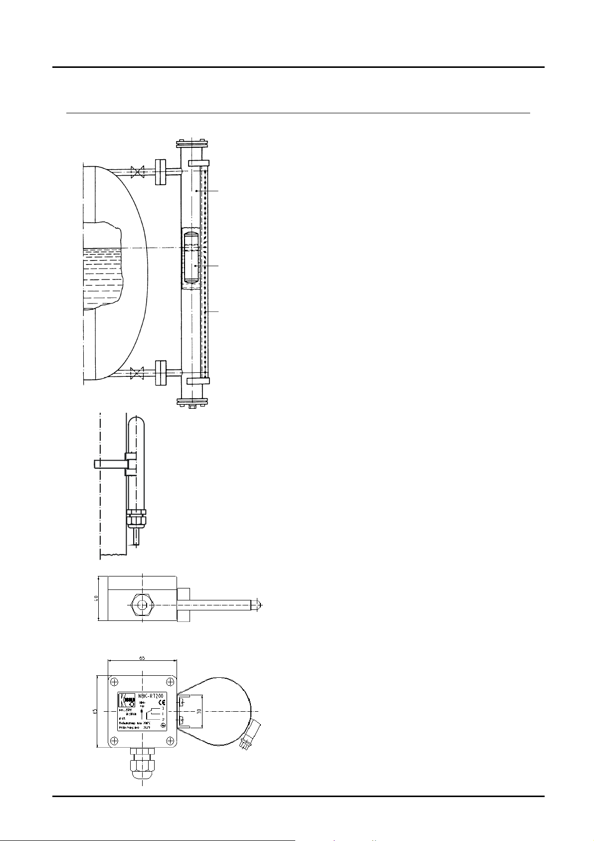
6. Mechanical Connection
Standpipe
Indicator
Float
Roller
indicator
Remove bottom flange from bypass
tube, and insert the cylindrical float in
the NBK bypass tube with the designation "TOP" at the top. Re-position the
gasket and close the bottom flange
again; firmly tighten with screws. Mount
and tighten the bypass tube to the vessel to be monitored with process connection and seal.
Normally it is sufficient to fix the complete NBK with both process connections. However should the NBK be subjected to constant shock or strong vibrations it is recommended that the instrument is secured with rubber-damped
tube clips.
The bypass tube should never be
welded.
Mount and tighten the magnetic roller
indicator - if not already mounted - on
the bypass tube with the two
accompanying ribbon clamps.
Mount and tighten the reed switch - if
available and not already mounted - on
the bypass tube at the opposite side of
the roller indicator with the
accompanying ribbon clamp (ex contact:
2 ribbon clamps).
The height of the switch contacts may
be selected at will. The cable connection
must point downwards. Tighten the tube
clips until the gap cannot be closed any
further. The switch must be snug
against the stand tube. The switching
function of the switch is impaired by an
enlarged air gap.
Mount and tighten remote sensor - if
available and not already mounted - on
the bypass tube with the ribbon clamp.
The remote sensor must cover both
process connections fully. The cable
terminal box is situated at the top.
Page 6 NBK-M K03/0717
Page 7

7. Electrical Connection
g
t
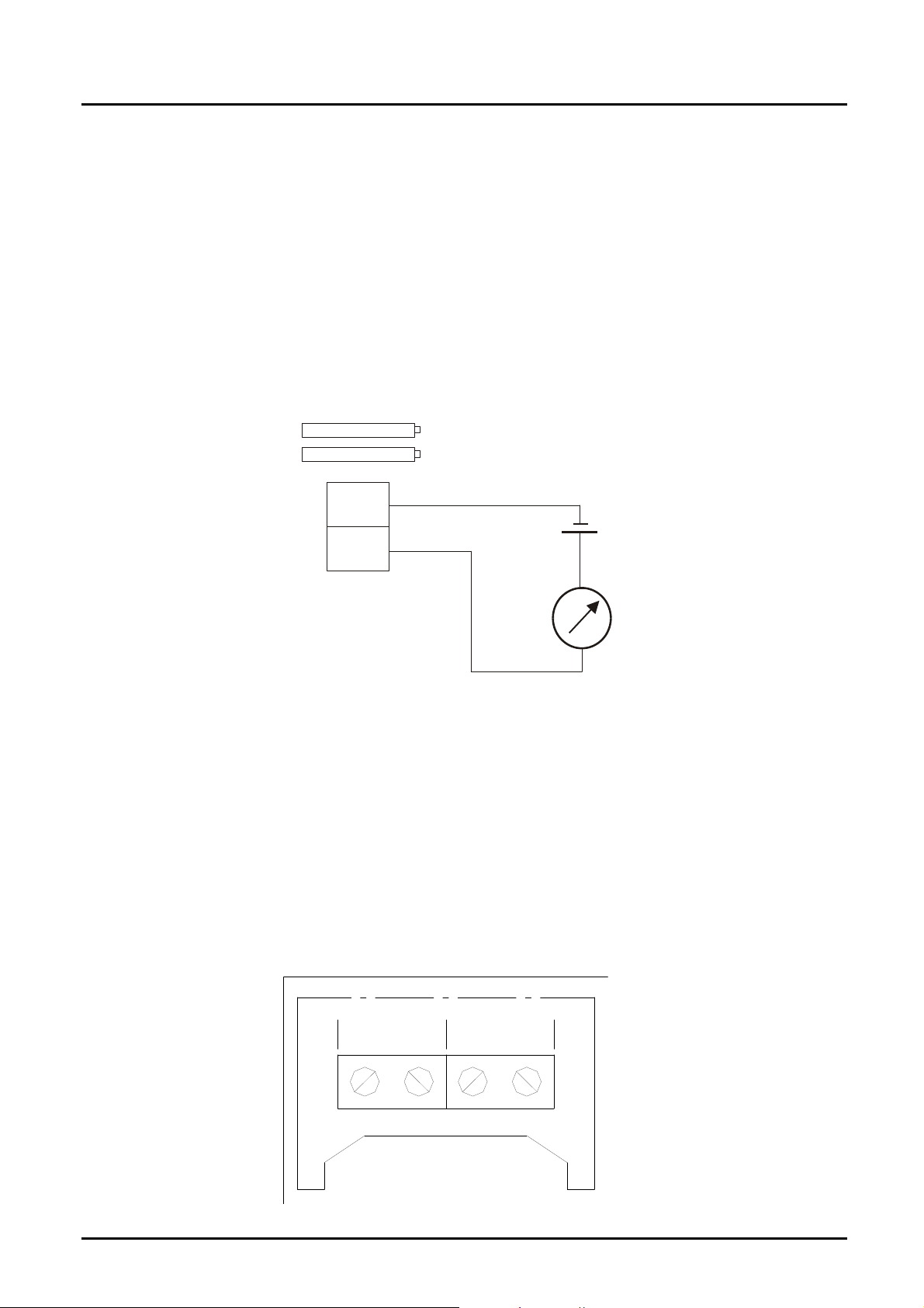
7.1. Switch (option)
Connect switch (if available) according to the diagram, and
W
ith cable connection
connect to the electrical controller.
NBK-M
blue
When switching inductive loads, such as, contactors, relays, etc,
bl
ack
brown
electrical limit values should not be exceeded by surges or
spikes, for instance. The use of a contact protection relay is
recommended to avoid overloading the reed contacts.
Connection box
Valid regulations for hazardous areas, and regulations for
installation (DIN/VDE 0165), should be observed when installing
3
2
1
the NBK level indicator in zone 1 or 2 hazardous areas (no
combustible liquids).
7.2. Remote sensor
Reed Contact Chain of Resistors (option ..W..)
Ensure that the electrical supply lines are powerless.
To avoid faults caused by electrical fields from other circuits, the cables should
not be installed adjacent to other cables.
Unscrew cover and run supply lines through cable gland.
Connect the remote sensor to the electronics according to following table.
Silicon cable
PVC cable
FEP cable
Adapter box
Internal *
Transmitter
"top"
white brown green
white brown green
brown blue black
terminal 1 terminal 2 terminal 3
yellow red black
Transmitter
"bottom"
Pick-off
1
2
3
op
bottom
nal
si
*Please note: The colours of internal cables are for internal connections
only and therefore are only visible in transmitters with connection box.
NBK-M K03/0717 Page 7
Page 8
NBK-M
C
When connecting remote sensors to a Kobold transmitter, for example models
DFA, DST or DFM, please read the relevant operating instructions.
7.3. Remote Sensor: Chain of Resistors with
Ensure that the electrical supply lines are powerless.
To avoid faults caused by electrical fields from other circuits, the cables should
not be installed adjacent to other cables.
Unscrew cover and run supply lines through cable gland.
Connect the remote sensor to the electronics according to the wiring diagram
below.
2-wire Transmitter (option ..M..)
-
-
16-32 V D
+
+
-
+
7.4. Remote Sensor: Magnetostrictive Sensor with
4-wire Transmitter (option ..T..)
Ensure that the electrical supply lines are powerless.
To avoid faults caused by electrical fields from other circuits, the cables should
not be installed adjacent to other cables.
Unscrew cover and run supply lines through cable gland.
Connect the remote sensor to the electronics according to the wiring diagram
below.
4-20 mA
Ao ut AG ND + US GND
Page 8 NBK-M K03/0717
24 VDC
± 20%
Page 9

8. Commissioning
Because of the setting behaviour of seals, all screw connections must be
retightened. Fill vessel, and switch on electrical controller, if existing. If there are
stopcocks between bypass process connection and tank, first slowly open the
upper valve (pressure relief) and then the lower valve (liquid side). If vent and
drain valves have been installed, close them before filling.
The liquid that now enters the bypass tube raises the float until the level between
tank and bypass tube is balanced. The roller indicator indicates the liquid level.
Commissioning Reed Switches
Function of switches
All switches have three connection poles (black (2), blue (1) and brown (3)).
The black wire (2) is the common pole for both switching functions (N/C and N/O
contact).
The float must pass the switch once in both directions so that the switching function is in line with the terminal connection diagram and table below.
These instructions are often ignored when an alarm lamp is connected with the
result that the alarm lamp incorrectly indicates a fault.
NBK-M
When the switch has been passed over for once, it is ready for operation and
requires no maintenance.
Note that the switch cable must point downwards.
black (2) / blue (1) black (2) / brown (3)
float above open electrical conductive
float below electrical conductive open
Hysteresis
Hysteresis is the difference between contact closing
and opening points. A hysteresis of approximately
15 mm float travel is achieved by factory tuning of the
float magnet and contact strength.
NBK-M K03/0717 Page 9
Page 10

NBK-M
9. Trouble Shooting
Error: The tank is full but there is no indication
Check that both flanges (process connection) top and bottom are open to the
vessel, and that the bypass tube fills with liquid.
Check that there is a float in the system.
When the float is installed, check whether it is being blocked by foreign objects
or dirt deposits.
Error: The tank is full but the indication is too low.
Check that the density of the liquid is the same as the density given on the
nameplate.
Check that the float has been correctly installed with the marking "TOP" at the
top.
Check if dirt deposits in the bypass tube are blocking the float.
10. Maintenance
The drain plug should be opened occasionally, to wash out any deposits in case
the liquid to be measured contains dirt particles, which could settle in the bypass
tube. If encrustations or crystallisation have formed, the tank must be emptied or
shut off; the lower cover flange must then be removed. The float should then be
removed carefully from the vessel. The bypass tube can now be mechanically
cleaned.
The inspection window for the roller indication is made of high-quality plexiglass
(glass for high-temperature display). It should be cleaned with a suitable cleaning
agent.
The indicator requires no further maintenance.
Page 10 NBK-M K03/0717
Page 11

NBK-M
11. Technical Information
Bypass tube: Ø 40 mm
Material: 1.4571
O-Ring (Ground flange): NBR 70 (-30...+100 °C)
(other materials as options)
Operating pressure: PN 6/16/40 – 150 lbs / 300 lbs
Operating temperature: to 120 °C PP rollers
to 200 °C ceramic rollers
Viscosity: max. 200 mm2/s
Max. measuring length: to 3000 mm one-piece
Total length: according to measuring length,
see dimension drawing
Float: titanium, closed
Special versions on request.
Limit contacts model NBK-R
Contact operation: bistable changeover contact
Switching hysteresis: approximately 15 mm
Max. switching capacity: 60 W/VA; 230 V
Medium temperature: max. 100 °C
Ambient temperature: max. 75 °C
Protection: IP 67
Connection: 3 m PVC cable
Case: plastic
Limit contacts model NBK-RT200
Contact operation: bistable changeover contact
Switching hysteresis: approximately 15 mm
Max. switching capacity: 80 VA; 250 V
Medium temperature: max. 200 °C
Ambient temperature: max. 145 °C
Protection: IP 65
die cast aluminium housing, terminal connection
Transmitter model: ...W...
Reed Contact Chain of Resistors
Total resistance: approximately 5 k
Measuring-voltage: max. 24 V
Measuring current: max. 0.1 A
Medium temperature: max. 200 °C
Ambient temperature: max. 130 °C
Protection: IP 65
Resolution: 10 mm (ML < 2000 mm)
20 mm (ML 2000 mm)
DC
AC/DC
AC/DC
; 1A
, 1.0 A
NBK-M K03/0717 Page 11
Page 12

NBK-M
Transmitter model: ...M...
Reed Contact Chain of Resistors with 2-wire Transmitter
Output: 4-20 mA
Power supply: 16-32 VDC
Load: (UB –9 V) / 0.02 A []
Medium temperature: max. 130 °C
Ambient temperature: max. 80 °C
Protection: IP 65
Resolution: 10 mm (ML<2000 mm)
20 mm (ML2000 mm)
Transmitter model: ...T...
Magnetostrictive Sensor with 4-wire Transmitter
Output: 4-20 mA / Load max. 500
Max. length: 3000 mm
Supply voltage: 24 VDC, max. 150 mA
Accuracy: ± 1mm
Temperature range: -20…+ 80 °C
Ambient temperature: max. 80°C
Protection: IP 65
12. Order Codes
Model
NBK-M
NBK-RM
NBK-RT200M
Nominal
Pressure
1= PN 6 (not with
ASME flange)
2= PN 16 (150 lbs)
3= PN 40 (300 lbs)
Connection
F= DIN Flange
A= ASME-Flange
R= Tube thread
N= NPT thread
Nominal
Diameter
10= DN 10 (only
with DIN-flange)
15= DN 15, 1/2"
20= DN 20, 3/4"
25= DN 25, 1"
High-temperature contact max. 200 °C
Indicator
0= without
P= PP roller
K= ceramic roller
Standard Limit Contact
Roller
Measuring
sensor
0= without
T= magnetostrictive
W= chain of resistors
M= chain of resistors
with transmitter
Medium
density
8= from 0.8 g/cm³
1= from 1.0 g/cm³
Options
0= without
...= (see list)
Page 12 NBK-M K03/0717
Page 13

NBK-M
13. Dimensions
NBK-M with roller indication
Dimension C [mm] for DIN V-flange
Model DN 10 DN 15 DN 20 DN 25
PN 6
PN 16
PN 40
Dimension C [mm] for ANSI V-flange
Model ½“ ¾“ 1“
150 lbs
300 lbs
Dimension C for R- or NPT thread: 60 mm
Dimension A: medium density 0,8 g/cm³: 290 mm
medium density 1,0 g/cm³: 185 mm
NBK-M K03/0717 Page 13
46 47 47 46
53 52 53 49
53 55 55 51
64 67 66
69 72 73
Page 14

NBK-M
NBK-M with roller indicator and magnetostrictive transmitter
Page 14 NBK-M K03/0717
Page 15

NBK-M
14. Options
B Display model ADI-B with bar graph rugged aluminum housing,
mounted on bypass tube, for description, see brochure Z2
C Display model ADI-K with bar graph and digital display, rugged aluminum
housing, mounted on bypass tube, for description, see brochure Z2
D Display model ADI-D with digital display, rugged aluminum housing
mounted on bypass tube for description, see brochure Z2
E1 Drain flange DN 15, stainless steel 1.4571
E2 Drain flange DN 20, stainless steel 1.4571
E3 Drain flange, ASME 1/2", stainless steel 1.4571
E4 Drain flange, ASME 3/4", stainless steel 1.4571
L1 Drain valve G 1/4, stainless steel 1.4571
L2 Drain valve 1/4 NPT, stainless steel 1.4571
H1 Rinsing connection DN 15/PN 16, top and bottom
H2 Rinsing connection ASME 1/2", 150 lbs, top and bottom
M1 Measuring scale to 200°C, aluminum, engraved scale
M2 Measuring scale to 120°C, aluminum, polyester foil scale
P Radiographic examination DIN 54111 T1
Q Dye penetration test DIN 541152
X Pressure test with water 1.5 x PN
Z 3.1 certificate as per EN 10204
R1 Drain screw, bottom, G 1/4, PTFE gasket
R2 Drain screw, bottom, 1/4 NPT, no gasket
W1 O-ring material (bottom flange): FPM
W2 O-ring material (bottom flange): silicone
W3 O-ring material (bottom flange): PTFE
W4 O-ring material (bottom flange): Kalrez/Chemraz
NBK-M K03/0717 Page 15
Page 16

NBK-M
15. EU Declaration of Conformance
We, Kobold-Messring GmbH, Hofheim-Ts., Federal Republic of Germany, hereby
declare that the bypass level indicators meet the following criteria.
The Mini Bypass Level Indicators with Limit Switches
model NBK-R
model NBK-RT
conform to the standards listed below:
EN 61010-1:2011
Safety requirements for electrical equipment for measurement, control and
laboratory use - Part 1: General requirements
EN 60529:2014
Degrees of protection provided by enclosures (IP Code)
The following Mini Bypass Level Indicators with Remote Sensors
model NBK-...M...
model NBK-...T...
model NBK-...W...
conform to the standards listed below:
EN 61000-6-4:2011
Electromagnetic compatibility (EMC) - Part 6-4: Generic standards - Emission
standard for industrial environments
EN 61000-6-2:2006
Electromagnetic compatibility (EMC) - Part 6-2: Generic standards - Immunity for
industrial environments
EN 61010-1:2011
Safety requirements for electrical equipment for measurement, control and
laboratory use - Part 1: General requirements
EN 60529:2014
Degrees of protection provided by enclosures (IP Code)
Page 16 NBK-M K03/0717
Page 17

NBK-M
The following EU directives are fulfilled:
2014/35/EU Low Voltage Directive
2014/30/EU Electromagnetic Compatibility Directive
2011/65/EU RoHS
Hofheim, 04. July 2017
H. Peters M. Wenzel
General Manager Proxy Holder
NBK-M K03/0717 Page 17
 Loading...