

Page 1
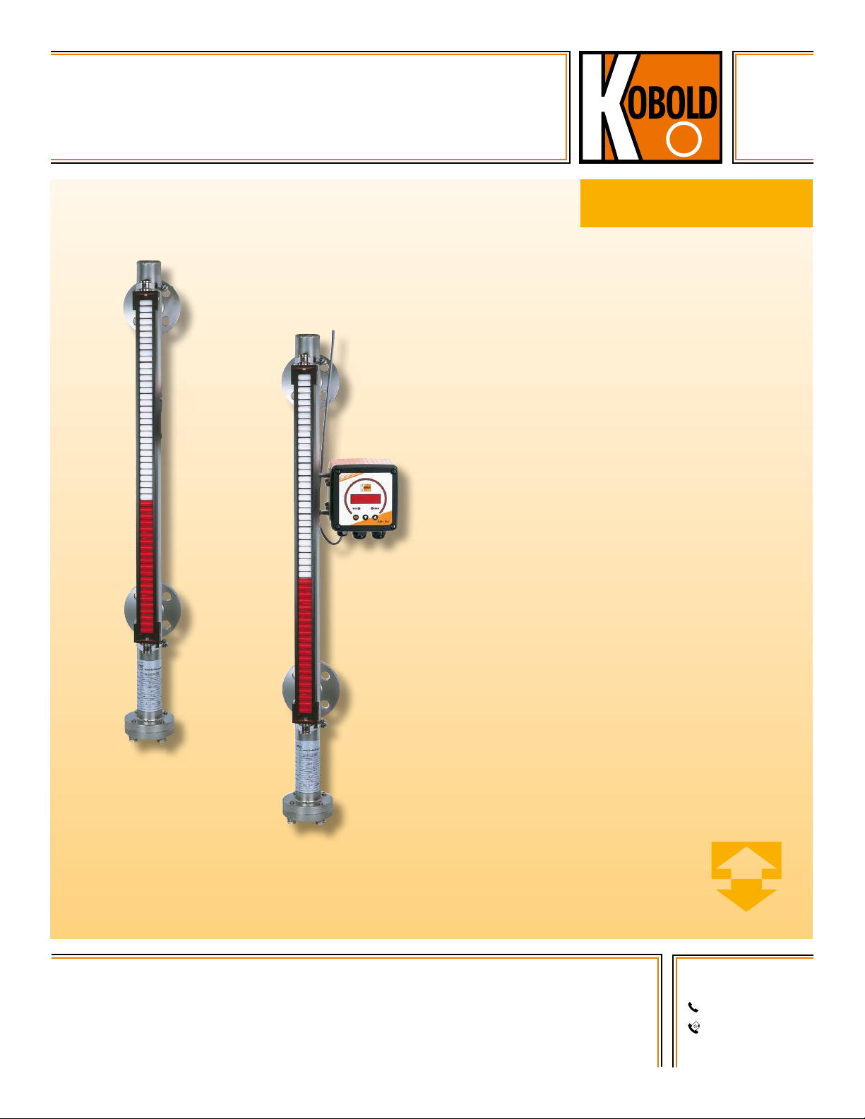
Economical Bypass Level Indicator
Mini-NBK
• 316 Stainless Steel Tube
• Max. Pressure: 580 PSIG
measuring
•
monitoring
•
analyzing
NBK-M
• Max. Temperature: 390 °F
• Measuring Lengths to 9.8 ft.
• Optional Switches, Transmitters,
and Digital Displays Available
• Rugged, Economical Design
KOBOLD companies worldwide:
ARGENTINA, AUSTRALIA, AUSTRIA, BELGIUM, BULGARIA, CANADA, CHILE, CHINA, COLOMBIA,
CZECH REPUBLIC, EGYPT, FRANCE, GERMANY, HUNGARY, INDIA, INDONESIA, ITALY, MALAYSIA,
MEXICO, NETHERLANDS, PERU, POLAND, REPUBLIC OF KOREA, ROMANIA, SINGAPORE, SPAIN,
SWITZERLAND, TAIWAN, THAILAND, TUNISIA, TURKEY, UNITED KINGDOM, USA, VIETNAM
01/09-19-2018
KOBOLD Instruments, Inc.
1801 Parkway View Drive
Pittsburgh, PA 15205
Main Ofce:
1.800.998.1020
1.412.788.4890
info@koboldusa.com
www.koboldusa.com
Page 2
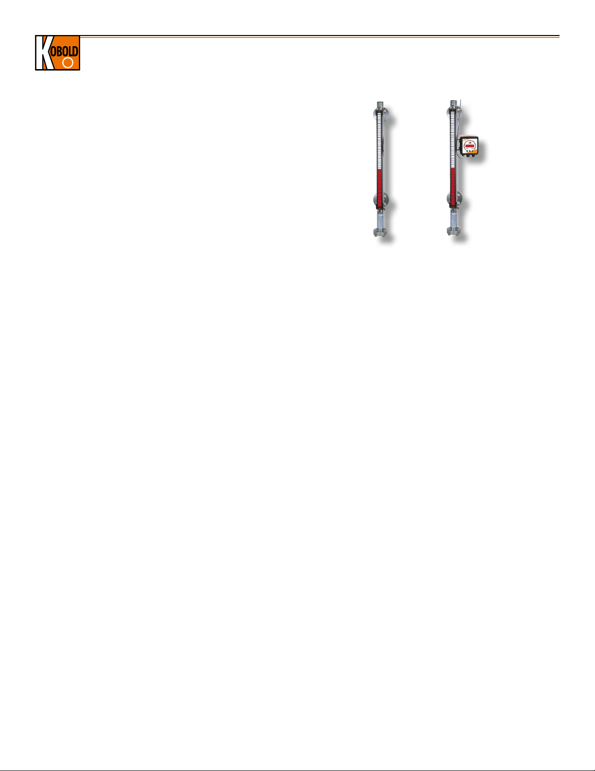
Economical Bypass Level Indicator Model NBK-M
Description
The KOBOLD NBK-M bypass level indicator provides many of the
unique features of our standard NBK, but at a fraction of the cost.
It uses our revolutionary ring magnet float design, allowing the
user full flexibility in adding roller indicators, switches, and other
options anywhere on the periphery of the bypass tube. The use of
lighter gauge materials makes the NBK-M an economical choice
for low pressure level measurement. A magnetic roller indicator
strip allows local level reading at the tank as they rotate from white
to red as the level changes. This assembly can be rotated in the
field to any position on the bypass tube for easier readings in tight
locations. Rollers are made of polypropylene for temperatures
under 250 °F and are made of ceramic for temperatures above.
SPDT switches are available for use in hi/low level alarms and
automatic tank fill/empty operations. The switch level setpoint is
adjusted in the field by sliding the switch assembly up or down on
the bypass pipe. Magnetostricitve and variable resistance level
transmitters are available for remote indicators or control systems.
A universial indicating unit, ADI series, can be mounted on the
bypass to display and evaluate the standard signal (4-20mA)
generated by the transmitter.
Specifications
Max. Pressure
Threaded Fitting: 580 PSIG
Flanged Fitting: Per ANSI B16.5 for the Specified Flange
Rating, up to 580 PSIG
Wetted Materials
Bypass Pipe, Fittings: 316-Ti Stainless Steel
Float: Titanium
Seals: NBR (-4...390 °F)(Standard)
FKM, Silicone, PTFE, FFKM (Optional)
Rollers: Polypropylene or Ceramic (Model Based)
IP54
Max. Liquid Viscosity: 200 Centistokes
Allowable Liquid S.G.
Float Type "8": 0.78...0.95
Float Type "1": Water, Liquid with S.G. > 0.95
Max. Measuring Length: 9.8 ft.
Electrical Specifications
Resistive, Level Transmitter: Option "W"
Output: Resistive, Approx. 0...5 kohm
Working Voltage: 24 VDC Max.
Working Current: 100 mA Max.
Resolution: ± 3/8" for Measuring Lengths < 6.6 ft.
± 3/4" for Measuring Lengths > 6.6 ft.
Max. Process Temp.: 390 °F
Max. Ambient Temp.: 265 °F
Electrical Connection: Cable Gland, PG 9
Electrical Protection: IP 65
Resistive, Head Mount Transmitter: Option "M"
Output: 4-20 mA, 2-wire
Supply Voltage: 16-32 VDC
Max. Loop Burden: (V
-9)/0.02 Ohms
Supply
Resolution: ± 3/8" for Measuring Lengths
< 6.6 ft, ± 3/4" for Measuring
Lengths > 6.6 ft.
Max. Process Temp.: 250 °F
Max. Ambient Temp.: 175 °F
Electrical Connection: Cable Gland, PG 9
Electrical Protection: IP 65
Magnetostrictive, Head Mount Transmitter: Option "T"
Output: 4-20 mA, 4-wire
Supply Voltage: 24 VDC ± 10%
Max. Loop Burden: 500 Ohms
Resolution: ±1 mm
Max. Process Temp.: 175 °F
Max. Ambient Temp.: 175 °F
Electrical Connection: Cable Gland, PG 9
Electrical Protection: IP 65
Low Temperature Switches: Model NBK-RM
Function: Bistable Reed Contact, SPDT
Ratings: Max. 60 Watt, 230 VAC, 0.8 A
Hysteresis: Approx. 1/2"
Max. Process Temp.: 212 °F
Max. Ambient Temp.: 165 °F
Electrical Connection: 10 ft. PVC Cable
Electrical Protection: IP 67
High Temperature Switches: Model NBK-RT200M
Function: Bistable, Magnetically
Activated, SPDT
Ratings: Max. 80 Watt, 230 VAC, 1.0 A
Hysteresis: Approx. 1/2"
Max. Process Temp.: 390 °F
Max. Ambient Temp.: 290 °F
Electrical Connection: Cable Gland, PG 9
Electrical Protection: IP 65
No responsibility taken for errors;
2
www.koboldusa.com
subject to change without prior notice.
Page 3

Economical Bypass Level Indicator Model NBK-M
Order Details (Example: NBK-M 2 A 15 P M 8)
Model Flange Rating FItting Type Fitting Size Roller Indicator Transmitter Float S.G.
..0.. = None
..0.. = No Flange
(Threaded Fitting)
..15.. = 1/2"
..A.. = ANSI Flange
..0.. = None
NBK-M..
..2.. = ANSI Class 150 lb
..20.. = 3/4"
..P.. = Polypropylene
(250 °F Max.)
..N.. = NPT Thread
..25.. = 1"
..3.. = ANSI Class 300 lb
..K.. = Ceramic
(390 °F Max.)
Options (Add Codes to Base Part Number)
..S2 = Vent Plug 1/4" NPT ..W1 = FKM Seal on the Bottom Flange (5...390 °F)
..S3 = Vent Plug 1/2" NPT ..W2 = Silicone Seal on the Bottom Flange (-76...390 °F)
..R2 = Drain Plug 1/4" NPT ..W3 = PTFE Seal on the Bottom Flange (-4...250 °F)
..R3 = Drain Plug 1/2" NPT ..W4 = FFKM Seal on the Bottom Flange (-4...390 °F)
..E3 = Drain Flange, ANSI 1/2" ..M1 = Engraved Level Measuring Scale, Max. Process Temp. 390 °F
..E4 = Drain Flange, ANSI 3/4" ..M2 = Laser Etched Level Measuring Scale, Max. Process Temp. 250 °F
..J = Upper Clean-out Flange ..C1) = Digital and Bargraph Display model ADI-1V00 WF
..L2 = Drain Valve, 1/4" NPT ..P = Radiographic Weld Testing per DIN 54111 T1
..L3 = Drain Valve, 1/2" NPT ..X = Hydrostatic Testing at 1.5x Nominal Pressure
..H2 = Top and Bottom Flush Connections, 1/2" ANSI Flange
Accessories (Order as Separate Line Items)
NBK-RM = Standard SPDT Contact, Max. Process Temperature 212 °F
NBK-RT200M = High Temperature SPDT Contact, Max. Process Temperature 390 °F
1)
Only available with level transducer T (magnetostrictive transmitter) or M (reed chain transmitter) ouput options
2)
For more accurate indication, floats can be wieghted per exact customer specified S.G.; consult factory for details
Dimensions
"C"
*Additional Information Required for Order:
To ensure proper operation, this product requires a
completed application guide form to be submitted with
any order. Please refer to the ‘documentation’ tab on
the bottom of the product page for this product on our
website in order to obtain the correct form. You can also
contact your KOBOLD representative for this form.
..M.. = Resistive,
4-20 mA
Transmitter
..T.. = Magnetostrictive,
4-20 mA
Transmitter
..W.. = Resistive,
0-5 Kohm
Output
..1 = 1.0
For use with
S.G > 0.95
..8 = 0.8
For use with
S.G 0.78...0.95
2)
No responsibility taken for errors;
subject to change without prior notice.
www.koboldusa.com
Clearance Dimensions "A"
Specific Gravity
0.8 1.0
11.22" 7.09"
Clearance Dimensions "C"
Type 1/2" 3/4" 1"
150 lb ANSI V Flange 2.52" 2.64" 2.60"
300 lb ANSI V Flange 2.72" 2.84" 2.88"
NPT Threaded 2.37" 2.37" 2.37"
3
 Loading...