

Page 1
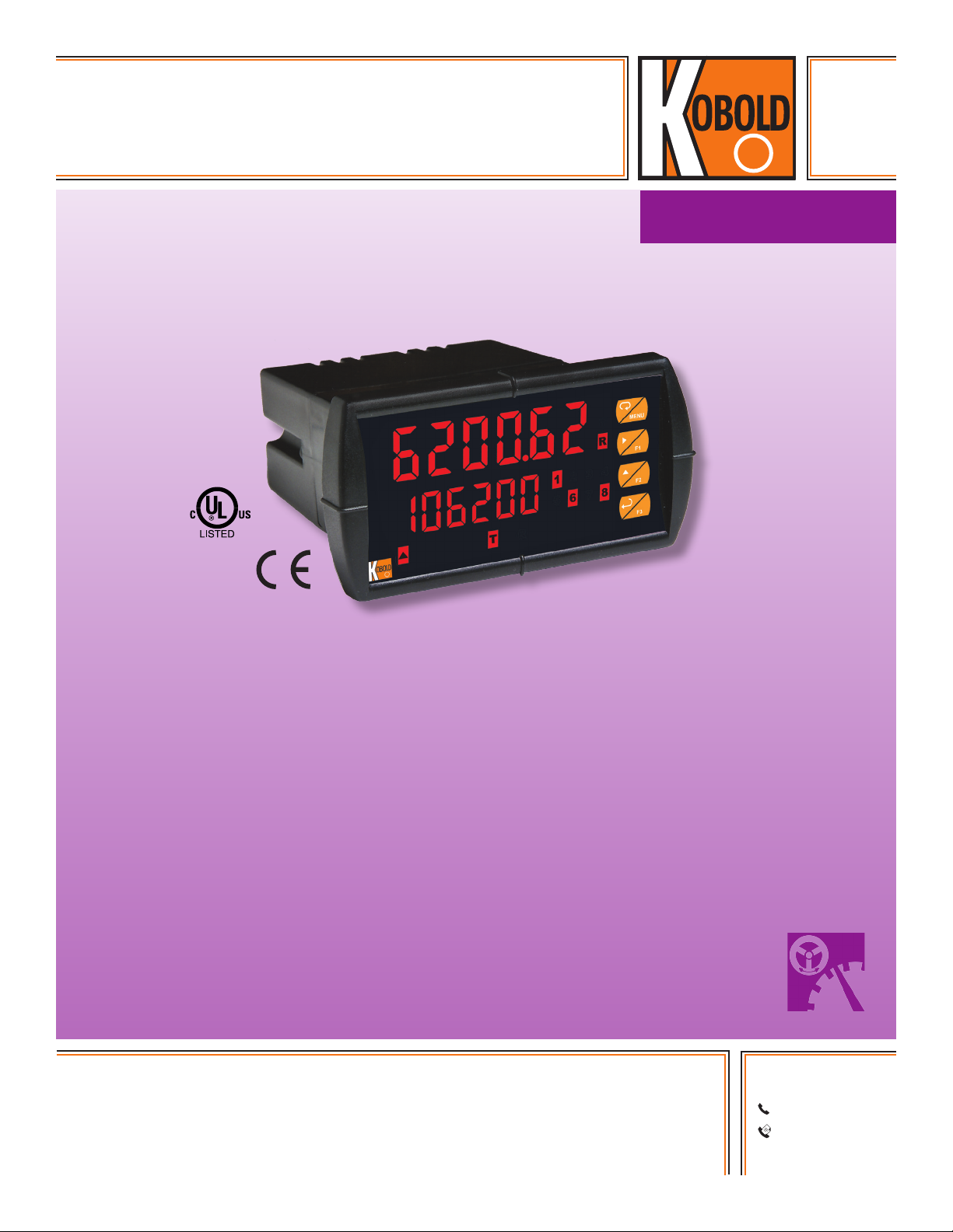
Process Panel Display
Dual-Line Rate and Total
measuring
•
monitoring
•
analyzing
MPV
• Pulse or Analog Inputs
• Displays Rate and Total Simultaneously
• Square Root Extraction
• 5, 10, or 24 VDC Flowmeter Power Supply
• K-Factor, Internal Scaling, or External Calibration
• 32-point Linearization with Free Software
• Open Channel Flow with Programmable Exponent
• Gate Function for Rate Display of Slow Pulse Rates
• Isolated 24 VDC @ 200 mA Transmitter Power Supply
• On-board Digital Input
• Modbus® RTU Communication Protocol
KOBOLD companies worldwide:
ARGENTINA, AUSTRALIA, AUSTRIA, BELGIUM, BULGARIA, CANADA, CHILE, CHINA, COLOMBIA, CZECH
REPUBLIC, EGYPT, FRANCE, GERMANY, HUNGARY, INDIA, INDONESIA, ITALY, MALAYSIA, MEXICO,
NETHERLANDS, PERU, POLAND, REPUBLIC OF KOREA, ROMANIA, SINGAPORE, SPAIN, SWITZERLAND,
TAIWAN, THAILAND, TUNISIA, TURKEY, UNITED KINGDOM, USA, VIETNAM
01/10-2015
KOBOLD Instruments, Inc.
1801 Parkway View Drive
Pittsburgh, PA 15205
Main Ofce:
1.800.998.1020
1.412.788.4890
info@koboldusa.com
www.koboldusa.com
Page 2
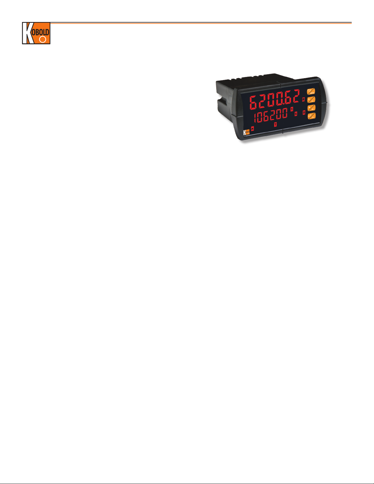
Process Panel Display Model MPV
Description
The MPV is designed for simultaneous display of both the flow
rate and total for flowmeters with analog or pulse outputs. The
upper display can be programmed to display flow rate, total,
or grand total and the lower display can be programmed to
display flow rate, total, grand total, engineering units, custom
legends, or can be turned off. Both displays are also capable of
displaying relay set points, or maximum and minimum values.
They are also able to provide power to the flowmeter. The MPV
features a rugged design with a unique front panel that is nearly
impenetrable in typical applications. Set-up is easy with the
user-friendly dual line display.
Specifications
Display: Upper Display: 0.60” (15 mm) high. Lower
Display: 0.46” (12 mm) high. Both are 6
digits (-99999 to 999999), red LEDs
Intensity: 8 Intensity Levels, User Adjustable
Update Rate: 5/second (200 ms)
Overrange: Flashes 999999
Underrange: Flashes -99999
Display
Assignment: The upper and lower displays may be
assigned to rate, total, grand total, alternate
(rate/total, rate/grand total, rate/units, total/
units, and grand total/units), max/min, units
(lower display only), set points, or Modbus
®
input. Additional displays are available if
parameter total is off, and parameter
d-SCAL is on: gross, alternating gross/net,
PV1, PV2, and PCT
Front Panel: NEMA 4X, IP 65
Programming
Methods: Four front panel buttons, digital inputs, PC
and MeterView Pro software, Modbus®
registers, or cloning using 'Copy' function.
Noise Filter: Programmable from 2 to 199 (0 disables)
Filter Bypass: Programmable from 0.1 to 99.9% of span
Recalibration: Calibrated by factory, recommended to
recalibrate at least every twelve months
Max/Min Display: Max (peak) and Min (valley) readings are
stored until user reset of power to meter is
cycled
Password: Three programmable passwords restrict
modification of programmed settings and
two prevent resetting the totals
Non-Volatile
Memory: All programmed settings are stored in non-
volatile memory for a minimum of ten years
if power is lost
Power Options: 85-265 VAC 50/60 Hz, 90-265 VDC 20 W
max, or jumper selectable 12/24 V
DC
±10%, 15 W max.
Isolated
Transmitter
Power Supply: Terminals P+ & P-: 24 VDC ± 10%. 12/24
VDC powered models selectable for 24, 10,
or 5 VDC supply (internal jumper J4). 85-265
VAC models rated @ 200 mA max, 12/24
VDC powered models rated @ 100 mA
max, @ 50 mA max for 5 or 10 VDC
supply
Normal
Rejection Mode: Greater than 60 dB at 50/60 Hz
Isolation: 4 kV input/output-to-power line, 500 V
input-to-output or output-to-P+ supply
Operating
Temp. Range: -40...149 °F
Storage
Temp. Range: -40...185 °F
Relative
Humidity: 0 to 90% non-condensing
Connections: Removable screw terminal blocks accept
12 to 22 AWG wire, RJ45 for external
relays, digital I/O, and serial comm.
adapters
Enclosure: 1/8 DIN, high impact plastic, UL-94V-0
Mounting: 1/8 DIN panel cutout required, 3.622"
x 1.772", bracket assemblies included
Tightening
Torque: Screw terminal connectors, 5 lb/in
Dimensions: 4.68” x 2.45” x 5.64”
Weight: 9.5 oz (269 g)
UL File Number: UL & c-UL Listed. E160849; 508
Industrial Control Equipment.
Warranty: 3 years parts & labor
*Except where noted all specifications apply to operation at 77 °F.
2
www.koboldusa.com
No responsibility taken for errors;
subject to change without prior notice.
Page 3

Process Panel Display Model MPV
Analog Input
Inputs: Field selectable: 0-20, 4-20 mA, ±10 V
DC
(0-5, 1-5, 0-10 V), Modbus PV (Slave)
Accuracy: ± 0.03% of calibrated span ±1 count,
square root & programmable exponent
accuracy range: 10-100% of calibrated
span
Temperature
Drift: 0.005% of calibrated span/°C max from 0
to 65°C ambient, 0.01% of calibrated
span/°C max from -40 to 0°C ambient
Signal Input
Conditioning: Linear, square root, programmable
exponent, or round horizontal tank volume
calculation
Multi-Point
Linearization: 2 to 32 points
Programmable
Exponent: 1.0001 to 2.9999
Low-Flow
Cutoff: 0-999999 (0 disables)
Decimal Point: Up to five decimal places or none
(x.xxxxx, xx.xxxx, xxx.xxx, xxxx.xx
xxxxx.x, xxxxxx)
Calibration Range:
Input Range Min Span Input 1 & 2
4-20 mA 0.15 mA
± 10 V 0.10 V
*Error message appears if input signals are too close
Input
Impedance: Voltage ranges: > 1 MΩ,
Current ranges: 50-100 Ω (depending on
resettable fuse impedance
Input
Overload: Current input protected by resettable fuse,
30 VDC Max, reset after fault is removed
Pulse Inputs
Inputs: Field selectable: pulse or square wave
0-5 V, 0-12 V, or 0-24 V @ 30 kHz; TTL;
open collector 4.7 kΩ pull-up to 5 V @ 30
kHz; NPN or PNP transistor, switch contact
4.7 kΩ pull-up to 5 V @ 40 Hz; coil (sine
wave) 40 mVp-p min @ 10 kHz; Modbus®
PV (Slave)
Low Voltage
Mag. Pick-up: Isolated, sensitivity of 40 mVp-p to 8 Vp-p
Min. Input
Frequency: 0.001 Hz (Min. frequency depends on
high gate setting)
Max. Input
Frequency: 30,000 Hz (10,000 for low voltage
mag. pick-up)
Pulse Inputs Continued
Input
Impedance: Pulse input is >300 kΩ @ 1 KHz, open
collector/switch input is 4.7 kΩ pull-up to
5 V
Accuracy: ± 0.03% of calibrated span ±1 count
Display
Update Rate: Total: 10/sec, Rate: 10/sec to 1/1000 sec
Temperature
Drift: Not affected by changes in temperature
Multi-Point
Linearization: 2 to 32 points
Low-Flow
Cutoff: 0-999999 (0 diasbles)
Decimal Point: Up to five decimal places or none
Calibration: May be calibrated using K-factor, scale
using internal calibration, or calibrate by
applying an external calibration signal
K-Factor: Field programmable K-factor converts input
pulses to rate in engineering units, may be
programmed from 0.00001 to 999,999
pulses/unit
Calibration
Range: Input 1 signal set anywhere, input 2 set above
Filter: Programmable contact de-bounce filter,
40 to 999 Hz max. input frequency
Time Base: Second, minute, hour, day
Low Gate: 0.1 to 99.9 seconds
High Gate: 2.0 to 999.9 seconds
Rate/Totalizer
Rate Display
Indication: 0 to 999999, “R” LED illuminates
Total Display
& Total
Overflow: 0 to 999,999, “T” LED illuminates and “GT”
for grand total, up to 999,999,999 with
total-overflow feature
Total Decimal
Point: Up to five decimal places or none,
total decimal point is independent of rate
decimal point
Totalizer: Calculates total based on rate and field
programmable multiplier to display total in
engineering units, time base must be
selected according to the time units in
which the rate is displayed, selectable
up/down count
Totalizer
Rollover: When display exceeds 999,999,999
relay status reflects the display value
Total Overflow
Override: Program total reset for automatic with 0.1
second delay and set point 1 for 999,999
No responsibility taken for errors;
subject to change without prior notice.
www.koboldusa.com
3
Page 4

Process Panel Display Model MPV
Rate/Totalizer Cont.
Totalizer
Presets: Up to 8, user selectable, any set point can
be assigned to total and be programmed
anywhere in the meter range
Total Reset
Delay: 0.1...999.9 seconds, applied to first relay
assigned to total or grand total, if meter is
programmed to reset total to zero
automatically when preset is reached then
a delay will occur before total is reset
Total Reset: Via front panel button, external contact
closure on digital inputs, automatically via
user selectable preset value and time delay,
or through serial communications
Total Reset
Password: Total and grand total passwords may be
entered to prevent resetting the total or
grand total from the front panel
Non-Resettable
Total: The grand total can be programmed as a
non-resettable total by entering the
password “050873”
Caution: Once the grand total has been programmed
as non-resettable, it can't be disabled
Relays
Rating: 2 or 4 SPDT (Form C) internal and/or 4 SPST
(Form A) external; rated 3 A @ 30 VDC and
125/250 VAC resistive load; 1/14 HP (≈ 50
watts) @ 125/250 VAC for inductive loads
such as contactors, solenoids, etc
Noise
Suppression: Recommended for each relay contact
switching inductive loads
Relay
Assignment: May be assigned to rate, total, grand total
Deadband: 0-100% of span, user programmable
High or Low
Alarm: Program any alarm for high or low trip point,
unused alarms and relays can be turned off
Relay
Operation: Automatic (non-latching), latching (requires
manual acknowledge), sampling (based
on time), pump alternation control (2 to
8 relays), off (disable unused relays and
enable interlock feature, manual on/off
control mode)
Relay Reset: User selectable via front panel buttons
digital inputs, or PC
1) Automatic reset only (non-latching)
when input passes reset or total reset to 0
2) Automatic + manual reset at any time
(non-latching)
3) Manual reset only, anytime (latching)
4) Manual reset after alarm clears (latching)
Relays Cont.
Note: Front panel button or digital input may be
assigned to acknowledge relays
programmed for manual reset
Time Delay: 0 to 999.9 seconds, on & off relay time
delays, programmable and independent for
each relay
Fail Safe
Operation: Programmable and independent for
each relay
Note: Relay coil energized in non-alarm condition,
in case of power failure, relay goes
to alarm state
Auto
Initialization: When power is applied to meter, relays
reflect state of input to meter
Isolated 4-20 mA Transmitter Output
Output
Source: Process variable (PV), max, min, set points
1-8, manual control setting, or Modbus®
input
Scaling
Range: 1.000 to 23.000 mA for any display range
Calibration: Factory calibrated: 4.000 to 20.000 = 4-20
mA output
Analog Output
Programming: 23.000 mA Max for all parameters:
overrange, underrange, max, min, break
Accuracy: ± 0.1% of span ± 0.004 mA
Temperature
Drift: 0.4uA/°C max from 0 to 65 °C ambient,
0.8 uA/°C max from -40 to 0 °C ambient
Note: analog output drift is separate from input
Isolated
Transmitter
Power Supply: Terminals I+ & R: 24 VDC ± 10%, may
be used to power the 4-20 mA output or
other devices, all models rated @ 40 mA
max.
External Loop
Power Supply: 35 VDC Max
Output Loop
Resistance: Loop Resistance
Power Supply Minimum Maximum
24 V
35 V
DC
DC
10 Ω 700 Ω
100 Ω 1200 Ω
No responsibility taken for errors;
4
www.koboldusa.com
subject to change without prior notice.
Page 5

Process Panel Display Model MPV
Serial Communications
Protocol: Modbus® RTU
Meter Address
Slave ID: 1-247
Baud Rate: 300-19,200 bps
Transmit Time
Delay: Programmable, between 0 and 199 ms
or transmitter always on for RS-422
Data: 8 bit (1 start bit, 1 or 2 stop bits)
Parity: Even, odd, or none with 1 or 2 stop bits
Byte-to-byte
Timeout: 0.01-2.54 seconds
Turnaround
Delay: Less than 2 ms (fixed)
Order Details (Example: MPV-4 5 2 4 R X)
Model Function
Operating
Voltage
Input Signal Output Options
..0 = None*
Connections
RELAY4 RELAY3
4 36 5 2 1
C NONO NC NC C
F4
P- COMP+ V+ mA+
3 41 2 5
DW1815
SIGNAL
Pulse Input Connections
RELAY2 RELAY1
4 36 5 2 1
C NONO NC NC C
6
1 2 3 4 5 6 7 8
M-LINK
Analog Input Connections
MA OUT
+
POWER
13 2
RI- I+
-
21
..1.. = Rate and Total
MPV-..
..4.. = Batching
Dimensions
..3.. = 12-36 V
..5.. = 85-265 V
2.45"
(62 mm)
0.59"
(15 mm)
DC
1.76"
(44.5 mm)
6" (152 mm) Clearance
Side View
..1.. = Pulse Input
..2.. = Analog Output
AC
(121 mm)
4.77"
5.05"
(128 mm)
..2 = Two SPDT Relays*
..3 = 4-20 mA*
..4 = Four Relays
..5 = 4-20 mA & Two SPDT Relays
..7 = 4-20 mA & Four SPDT Relays
R
C
+
C
NO
NC
NC
Optional
Connectors
Installed
3.61"
(91.5 mm)
-
4.68"
(119 mm)
Top View
NO
C
NC
..B = RS-422/485 Serial Adapter
..E = Custom Set-up
..G = Meter Copy Cable
..R = 4x Relay Expansion Module
..S = Digital I/O Expansion Module
..X = NEMA 4X Enclosure
*Output Option Only Available for MPV-1 Models
C
NO
NC
NO
4.17"
(106 mm)
No responsibility taken for errors;
subject to change without prior notice.
www.koboldusa.com
5
 Loading...