

Page 1
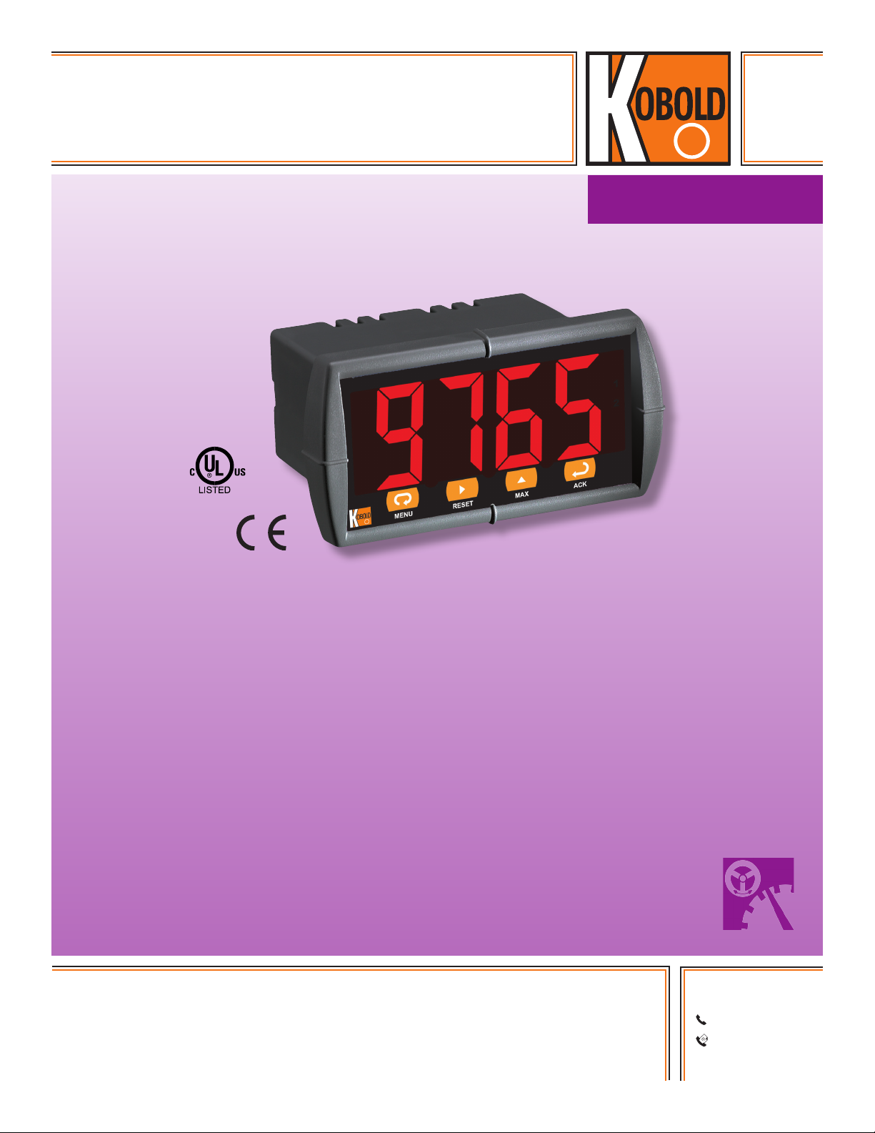
Universal Panel Display
Large or Small Digit Ratemeter
measuring
•
monitoring
•
analyzing
MPT
• Accepts Current, Voltage, TC, & RTD Inputs
• 4-Digit Display, 1.20” (30.5 mm) or 0.56" (14.2 mm)
• Linear or Square Root with Low-Flow Cutoff
• Maximum/Minimum Display
• Type 4X, NEMA 4X, IP65 Front
• Universal Power Supply 85-265 VAC
• 12-36 VDC Power Option
• Two Relays and 4-20 mA Output Option
• 24 VDC Transmitter Power Supply Options
• USB Serial Communication Adapter Option
• Free Modbus® RTU Protocol
KOBOLD companies worldwide:
ARGENTINA, AUSTRALIA, AUSTRIA, BELGIUM, BULGARIA, CANADA, CHILE, CHINA, COLOMBIA, CZECH
REPUBLIC, EGYPT, FRANCE, GERMANY, HUNGARY, INDIA, INDONESIA, ITALY, MALAYSIA, MEXICO,
NETHERLANDS, PERU, POLAND, REPUBLIC OF KOREA, ROMANIA, SINGAPORE, SPAIN, SWITZERLAND,
TAIWAN, THAILAND, TUNISIA, TURKEY, UNITED KINGDOM, USA, VIETNAM
01/10-2015
KOBOLD Instruments, Inc.
1801 Parkway View Drive
Pittsburgh, PA 15205
Main Ofce:
1.800.998.1020
1.412.788.4890
info@koboldusa.com
www.koboldusa.com
Page 2

Universal Panel Display Model MPT
Description
KOBOLD’s MPT is a versatile, easy to use, compact display built
for a wide range of applications. Programming is exceptionally
easy and can be done directly in the field through a variety
of options. It can be done via buttons on the front as there
are no switches or jumpers, nor is there a need to open the
case. It also includes a convenient 'copy' function that comes
standard. The MPT display intensity is adjustable to allow for
various lighting conditions, including direct sunlight. It also
offers current overload protection that resets itself once the
fault is removed. Installation is quick and easy thanks to locked
mounting brackets and removeable screw terminal connectors.
Specifications*
Display: 1.20" (30.5 mm) or 0.56" (14.2 mm)
Red LED, 4 Digits (-1999 to 9999)
Display
Intensity: Eight User Selectable Levels
Front
Panel: NEMA 4X, IP65; Panel Gasket Provided
Programming
Methods: Four Front Panel Buttons, Cloning with
'Copy' Feature, PC with MeterView
or LabVIEW Software, and Modbus®
Registers. Certified LabVIEW
Driver Available
Noise Filter: Programmable 2 to 199 (0 will Disable
Filter)
Display Update
Rate: Process/RTD: 3.7-5/sec; TC: 1.8-2.5/sec
Max/Min
Display: Stored until Reset by User or Meter is
Turned Off
Password: Restricts Modification of Programmed
Settings
Non-Volatile
Memory: Settings Stored for a Minimum of 10 Years
Power Options: 85-265 VAC, 50/60 Hz; 90-265 VDC, 20 W
Max. or 12-36 VDC; 12-24 VAC, 6 W Max.
Required Fuse: UL Recognized, 5 A Max., Slow-blow; up to
6 Meters May Share One Fuse
Normal Mode
Rejection: 64 dB at 50/60 Hz
Isolation: 4 kV Input/Output-to-power Line;
500 V Input-to-output or Output-to-24 VDC
Supplies
Operating
Temperature: 32...149 °F
Storage
Temperature: -40...185 °F
Relative
Humidity: 0 to 90% Non-condensing
Connections: Power & Signal: Removable Screw
Terminal Blocks accept 12 to
22 AWG. Serial: RJ11 Header, Standard
on all Meters
*Except where noted all specifications apply to operation at 77 °F.
Enclosure: 1/8 DIN, High Impact Plastic,
94V-0, Color; Gray
Weight: 9.5 oz (269 g) (Including Options)
UL File Number: E160849; 508 Industrial Control
Equipment
Warranty: 3 years Parts & Labor
Process Inputs
Inputs: Field Selectable,
4-20 mA, 1-5 V, 0-10 V
Accuracy: ± 0.05% FS ± 1 Count; Square Root:
± 0.1% FS ± 2 Counts
Function: Linear or Square Root
Low-Flow
Cutoff: 0 to 9999 (Disables Cutoff Function)
Decimal Point: Up to 3 Decimals, (x.xxx, xx.xx, xxx.x,
or xxxx)
Calibration: Scale without Signal or Calibrate with
Signal Source
Calibration
Range: User Programmable over Entire Range
of Meter
Input
Impedance: Voltage Range: Greater than 1 MΩ
Current
Range: 50-100 Ω, Varies with Resettable Fuse
Impedance
Input Overload: Protected by Automatic Reset Fuse
Temperature
Drift: ± 50 PPM/°C
Transmitter
Supply: Isolated, One or Two Transmitter
Supplies
P1: 24 VDC ± 10% @ 200 mA Max.
P1 & P2: 24 VDC ± 10% @ 200 mA & 40 mA
Max.
No responsibility taken for errors;
2
www.koboldusa.com
subject to change without prior notice.
Page 3

Universal Panel Display Model MPT
Temperature Inputs
Inputs: Factory Calibrated, Field Selectable: Type
J, K, T, or E Thermocouples and 100 Ω
Platinum RTD (0.00385 or 0.00392 Curve)
Resolution: 1°; Type T: 1° or 0.1°
Cold Junction
Reference: Automatic
Temperature
Drift: ± 2 °C Maximum
Offset
Adjustment: Programmable to ± 19.9°. This Parameter
Allows the User to Apply an Offset Value to
the Temperature being Displayed
Input
Impedance: Greater than 100 kΩ
Sensor Break: All Relays and Alarm Status LEDs go to
Alarm State
Type Range Acc. Range Acc.
J -58...1,382 °F ± 2 °F -50...750 °C ± 1 °C
K -58...2,300 °F ± 2 °F -50...1,260 °C ± 1 °C
T -292...700 °F ± 2 °F -180...371 °C ± 1 °C
E -58...1,700 °F ± 2 °F -50...927 °C ± 1 °C
RTD -328...1,382 °F ± 1 °F -200...750 °C ± 1 °C
Relays
Rating: 2 Form C (SPDT); Rated 3 A @ 30 VDC or
3 A @ 250 VAC Resistive Load; 1/14 HP
@ 125/250 VAC for Inductive Loads
Deadband: 0-100% FS, User Selectable
High or Low
Alarm: User May Program any Alarm for High or
Low
Relay
Operation: 1. Automatic (Non-latching) 2. Latching
3. Pump Alternation Control
Relay Reset: User Selectable via Front Panel Buttons or
PC
1) Automatic Reset Only (Non-latching)
2) Automatic Plus Manual Reset at any
Time (Non-latching)
3) Manual Reset Only, at any Time (Latching)
4) Manual Reset Only After Alarm Condition
has Cleared (Latching)
Automatic
Reset: Relays Reset when Input Passes the
Reset Point
Manual Reset: Front Panel Button, MeterView, Modbus®
Registers
Time Delay: 0 to 199 Seconds, On and Off Delays;
Programmable
Relays Continued
Time Delay: 0 to 199 Seconds, On and Off
Delays; Programmable
Fail-Safe
Operation: Programmable, Independent
for Each Relay. Relay Coils are
Energized in Non-alarm
Condition. In Case of Power
Failure, Relays will go to Alarm
State
Auto
Initialization: When Power is Applied to the
Meter, Relays will Reflect the
State of the Input to
the Meter
Isolated 4-20 mA Transmitter Output
Scaling Range: 1.00 to 23.00 mA; Reverse
Scaling Allowed
Calibration: Factory Calibrated 4.00 to 20.00
mA
Accuracy: ± 0.1% FS ± 0.004 mA
Temperature Drift: 50 PPM/°C
Note: Analog Output Drift is Separate
from Input Drift
Isolation: 500 V Input-to-output or
Output-to-24 VDC Supplies;
4 kV Output-to-power Line
External Power: 35 VDC Maximum
Output Loop
Resistance: Loop Resistance
Power Supply Minimum Maximum
24 V
35 V
DC
DC
10 Ω 700 Ω
100 Ω 1200 Ω
Serial Communications
Compatibility: EIA-232, and EIA-485 with
Adapters
Protocol: PDC and Modbus® RTU
Meter Address: PDC Protocol: 0 to 99,
Modbus® Protocol: 1 to 247
Baud Rate: 300 to 19,200 bps
Transmit Time Delay: Programmable 0 to 199 ms,
Transmitter Always on for RS-422
Data: 8 Bit (1 Start Bit, 1 Stop Bit)
Parity: None (2 Stop Bits), Even, or
Odd (Modbus® Only; PDC
Protocol does not Use Parity)
Byte-to-Byte Timeout: 0.01 to 2.54 Seconds (Modbus®
Only)
Turn Around Delay: Less than 2 ms (Fixed)
No responsibility taken for errors;
subject to change without prior notice.
www.koboldusa.com
3
Page 4

Universal Panel Display Model MPT
Gasket
Order Details (Example: MPT-12512E)
Model Function Display Size Operating Voltage Sensor Supply Output Options
..0 = None
MPT-.. ..1.. = Rate
..1.. = 0.56"
..2.. = 1.2"
..3.. = 12-36 V
..5.. = 85-265 V
DC
AC
..0.. = without
..0.. = without
..1.. = 24 VDC
..2 = 2x SPDT Relays
..3 = 4-20 mA
..4 = 2x SPDT Relays
& 4-20 mA
..B = RS-422/485 Serial Adapter
..E = Custom Set-up*
..F = USB to Software Adapter
..G = Meter Copy Cable
..X = NEMA 4X Enclosure
..5.. = 85-265 V
..2.. = Dual 24 VDC ..3 = 4-20 mA
AC
*Please specify input/output vs display parameters as a note on your order (i.e. 4 mA input = display 0, 20 mA input = display 100)
Connections
Front Bezel
RELAY2 RELAY1
4 36 5 2 1 2 12 1
COM NONO NC NC COM
EXC T+V+ mA+ COM
3 41 2 5
24V OUT POWER
P+ P-
RTD
TC
RTD
SWITCH
1 2 3 4 5 6
TC
-
+
Dimensions: inches (mm)
1.76 (45)
2.50
(64)
2.45
(62)
0.59
(15)
3.2 (81)
3.6 (91)
3.61
(92)
4.68 (119)
No responsibility taken for errors;
4
www.koboldusa.com
subject to change without prior notice.
 Loading...