

Page 1
Operating Instructions
for
Liquid Level Transducer
Model : MM Series
Page 2

MM series
page 2 DT0593
1 Contents
1 Contents ........................................................................................................ 2
2 Note .............................................................................................................. 3
3 Instrument Inspection .................................................................................... 3
4 Regulation Use .............................................................................................. 4
5 Float designs ................................................................................................. 4
6 Operating Principle ........................................................................................ 5
7 Mechanical Connection ................................................................................. 5
8 Area of application ........................................................................................ 5
9 Maintenance .................................................................................................. 6
10 Technical details ........................................................................................... 6
11 Head transmitter ............................................................................................ 7
12 Display .......................................................................................................... 8
13 Electrical Connection .................................................................................... 8
13.1 General ................................................................................................ 8
13.2 Wiring diagram resistance output sensor ............................................. 8
13.3 Wiring diagram with transmitter ........................................................... 9
13.4 Wiring diagram with touch screen LCD display type D ........................ 9
13.5 Wiring diagram with touch screen LCD display type R ........................ 9
13.6 Wiring diagram with LCD display type C .............................................. 9
13.7 Wiring diagram with LED display type E .............................................. 9
13.8 Electrical connection in intrinsically safe mode Ex ia ......................... 10
13.9 Electrical connection in explosion proof mode Ex d ........................... 10
14 Safety Instructions ( ATEX ) ........................................................................ 11
14.1 Area of validity ................................................................................... 11
14.2 Guidelines. ......................................................................................... 11
14.3 Protection against ESD ( electro static discharges ) .......................... 12
14.4 Chemical resistance ........................................................................... 12
14.5 Maintenance and repairs ................................................................... 12
14.6 Storage .............................................................................................. 12
15 Installation in hazardous zone ..................................................................... 13
16 ATEX Label Description .............................................................................. 13
17 Declaration of conformity ATEX Ex ia ......................................................... 14
18 Declaration of conformity ATEX Ex d .......................................................... 15
19 Declaration of conformity ............................................................................ 16
20 EC-TYPE CERTIFICATE ............................................................................ 17
21 Notes ........................................................................................................... 27
Manufactured by:
Kobold Mesura S.L.U.
Avda. Conflent 68 nave 15
08915 Badalona
Tel.: +34 93 460 38 83
Fax: +34 93 460 38 76
E-Mail: info.es@kobold.com
Internet: www.kobold.com
Edition: June 2017
Page 3

MM series
page 3 DT0593
2 Note
Please read these operating instructions before unpacking and setting the unit into
operation. Follow the instructions precisely as described herein.
The devices are only to be used, maintained and serviced by persons familiar with
these operating instructions and in accordance with local regulations applying to
Health & Safety and prevention of accidents.
When used in machines, the measuring unit should be used only when the
machines fulfil the EC-machine guidelines.
3 Instrument Inspection
Instruments are inspected before shipping and sent out in perfect condition.
Should damage to a device be visible, we recommend a thorough inspection of the
delivery packaging. In case of damage, please inform your parcel service /
forwarding agent immediately, since they are responsible for damages during
transit.
Scope of delivery:
The standard delivery includes:
Liquid Level Transducer model: MM-...
Operating Instruction
Caution: Heavy mechanical stress, such as bending, impact or shock
loads to the level transducer could damage the transducer and/or the
magnet.
Page 4

MM series
page 4 DT0593
4 Regulation Use
Kobold level transducers are used for the continuous level indication and level
control of all kinds of liquids. The simple design with only one moving part (the
float) is suitable for applications that demand reliability. Kobold level transducers
allow the continuous level indication and level control of liquids unaffected by
electrical conductivity, temperature, pressure. The level transducer may only be
used in liquids that will assure free movement of the float. The following points
must be noted:
no large particles
density of the fluid must not be less than that specified for the float type
pressure and temperature to be held within the limits given in the technical
specifications
A variety of transducers in various designs, connecting configurations and
materials are available for the acquisition of the measuring values.
Attention! These units should not be installed in the vicinity of strong
magnetic fields, since this can impair their intended functionality.
5 Float designs
Model Form Materials
Float
Outside
[mm]
Height
[mm]
Bore
Hole
[mm]
Min. Liquid
Density
[kg/dm³]
Max.
Temperature
°C
Nominal
Pressure
[bar] at
20 °C
MM05
Cylinder
hollow
PP 42 40 14 > 0.6 -10...+80°C 3 bar
MM07
Cylinder
hollow
PVC-U 42 40 14 > 0.9 0...+60 °C 3 bar
MM08
Cylinder
hollow
St. steel
1.4404
44 52 15 > 0.65 -20...+130°C 20 bar
MM10
Ball
hollow
St. steel
1.4404
52 52 15 > 0.6 -20...+130°C 30 bar
MM13
Cylinder
hollow
PVDF 38 60 18 > 0.6 -10...+125°C 2 bar
MM15
Cylinder
hollow
PP 60 60 18 > 0.4 -10...+80ºC 6 bar
MM16
Cylinder
hollow
PVC-U 60 60 18 > 0.6 0...+60°C 3 bar
MM20
Ball
hollow
St. steel
1.4404
95 95 20.8 > 0.5 -10...+130°C 15 bar
Page 5
MM series
page 5 DT0593
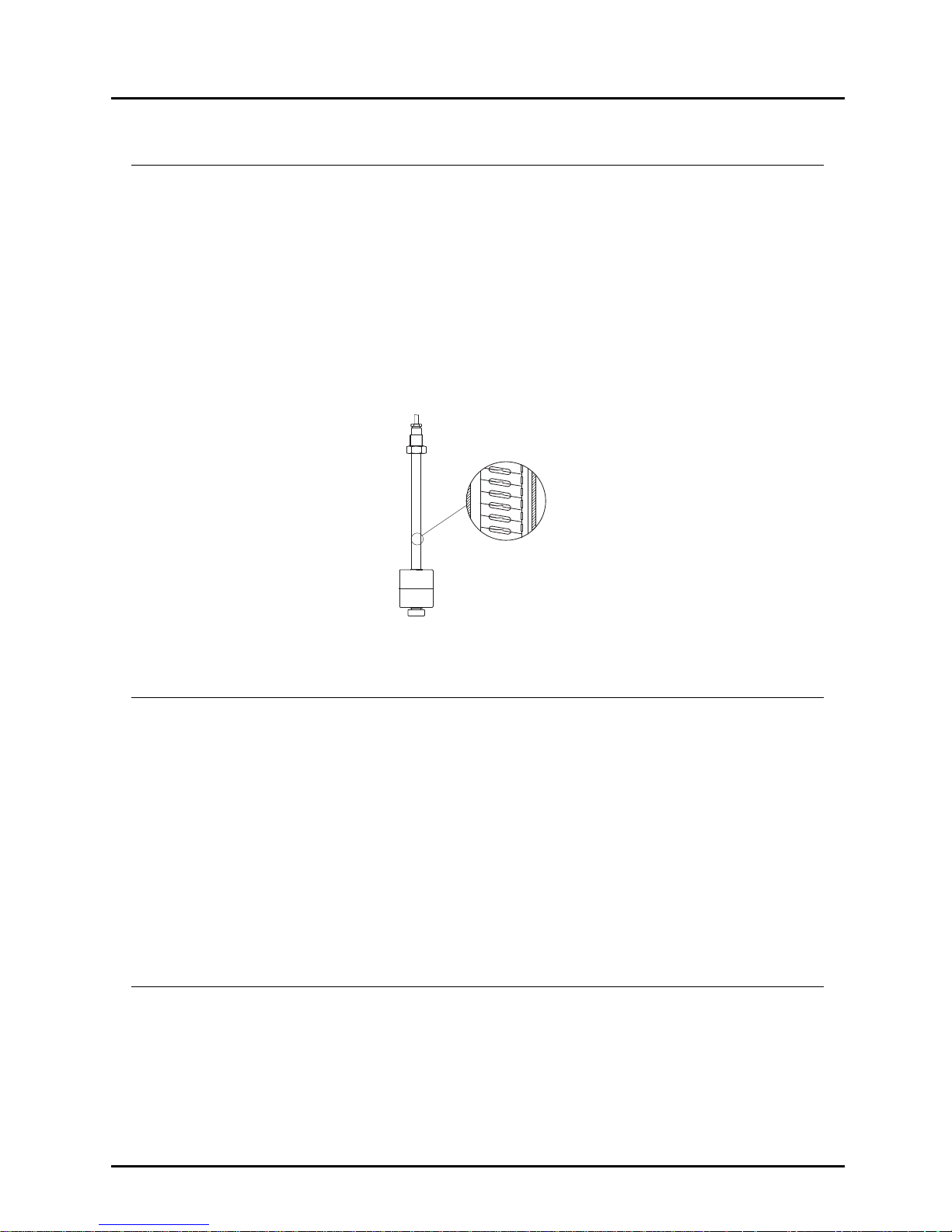
6 Operating Principle
The Kobold-liquid Level Transducers consist of a tube on which a float travels with
inserted magnet, similar to the Kobold level float switch, in models without float on
the tube, the float is placed in and adjacent bypass tube to actuate the reed chain
contacts, however, in the MM, the magnet remotely actuates the reed contacts
inside the tube.
However, the well-known principle of the level float switch has been changed, in
such a way that the tube of the level transducer contains an electric resistance
chain and a reed contact chain.
The float remotely actuates the contacts through the tube wall and a voltage
proportional to the liquid level can be taken from the chain. This voltage sensing
corresponds to the function of the slide of a resistance potentiometer.
7 Mechanical Connection
The reed chain tube should not be bent or exposed to hard impacts, since
otherwise the reed contacts inside the tube can be damaged.
Ensure the correct use of cable gland and gasket on float switches with plug to
prevent the penetration of humidity.
While installation is carried out, please ensure that the float can move freely (due
allowance should be given to distances from side-walls!).
Mounting position of the slide-tube may not deviate more than ±30° from vertical
position.
If the float has to be removed, pay attention to correct orientation when replacing
the float.
8 Area of application
Magnetic level sensor MM series are used exclusively for level control and
monitoring of liquid media.
The liquids should not contain suspended solids or tendency to crystallize.
Ensure that the construction materials of the float switch have chemical resistance
sufficient to prevent mechanical deformations that may affect it.
Page 6

MM series
page 6 DT0593
9 Maintenance
In liquids that can cause deposits, the float has to be cleaned at regular intervals.
In this case the measuring tube and float should be cleaned from such deposits
(valid for models where float is directly guided on the reed chain). Other
maintenance jobs are not required.
10 Technical details
Power supply: Output resistance: max. 24Vdc, 125 mW.
Ex ia parameters: Pi: 1,2W
Output 4…20 mA and 4…20 mA HART
®
: 8…35 Vdc
Ex ia parameters: Ui:30 Vdc, Ii: 120 mA, Pi: 0,84 W,
Li: 10uH, Ci: 1 nF
Output transmitter PROFIBUS
®
/FIELDBUS® : 9…32 Vdc
Ex ia parameters:
Ui:30 Vdc, Ii: 120 mA, Pi: 0,84 W,
Li: 1uH, Ci: 2 nF
Version with display model D: 14,5…35 Vdc
Ex ia parameters:
Ui:30 Vdc, Ii: 100 mA, Pi: 0,75 W,
Li: 10uH, Ci: 15 nF
Version with display model R: 14,5…35 Vdc
Relays 0…60 Vp, 75 mA
Ex ia parameters display:
Ui:30 Vdc, Ii: 100 mA,
Pi: 0,75 W, Li: 10uH, Ci: 15 nF.
Ex ia parameters relays:
Ui:30 Vdc, Ii: 75 mA, Pi: 0,75 W,
Li: 10uH, Ci: 10 nF
Version with display model C: 10…35 Vdc
Version with display model E: 11,7…35 Vdc
Protection type: IP65 (IP68 possible with housing type L, C,
and E)
Min. liquid density: See float design table
Min. measuring length “L”: 300 mm
Max. measuring length “L”: 6000 mm (types M08, M10, M20)
5000 mm (types M15, M17, M13)
2000 mm (types M05, M07)
Page 7

MM series
page 7 DT0593
Max. pressure (at 20ºC): 2 bar (type M13)
3 bar (type M05, M07, M16)
6 bar (type M15)
15 bar (type M20)
20 bar (type M08)
30 bar (type M10)
Max. temp. with PVC cable: 60ºC (type M07, M16)
70ºC (type M05, M15, M13, M08, M10, M20)
Max. temp. with. silicone cable: See max. temperature in float design table
Resolution: 10 mm
Accuracy: Formula in accordance to the measuring length
10 x 100 : measuring length = accuracy %
e.g.: 10 x100 : 2000 = 0,5 %
Resistance value: 36 Ω for each 10 mm, when total
length <1900 mm
10 Ω for each 10 mm, when total
length ≥1900 mm
e.g.: 2000 : 10 x 10 = 2000 ohms
1800 : 10 x 36 = 6480 ohms
Material: PVC-U, PP, PVDF, 1.4404
(others on request)
Process connection: G 3/8, G 1/2, G 1, G 1 ½, G 2, 3/8” NPT,
½” NPT, 1” NPT, 1 ½” NPT, 2” NPT and
flanged version. (others on request)
11
Head transmitter
Model 5333D: analogue output 4…20 mA, 2 wires,
Sensor error action : Namur upscale (23 mA)
Model 5337D: analogue output 4…20 mA HART
®
-protocol, 2 wires
Sensor error action : Namur upscale (23 mA)
Model 5350B : PROFIBUS
®
/FIELDBUS®
Page 8
MM series
page 8 DT0593
12 Display
- Only for 4…20 mA or HART
®
transmitters.
- Supply Voltage: loop powered
- Voltage dropout: max. 4 or 6,5 Vdc model D
max. 3,7 Vdc model E
max. 2,5 Vdc model C
Note
For programming of transmitter and/or display please refer to their separates
programming manual.
13 Electrical Connection
13.1 General
- Make sure that the supply wires are de-energized.
- To reduce the possibility of interference from other electric circuits, the
cables should be wired separately.
- Please pay attention to the potentially detrimental operating conditions
regarding the placement of the cable.
- Connect the level transducer to the electronic in accordance with the
connection diagrams below.
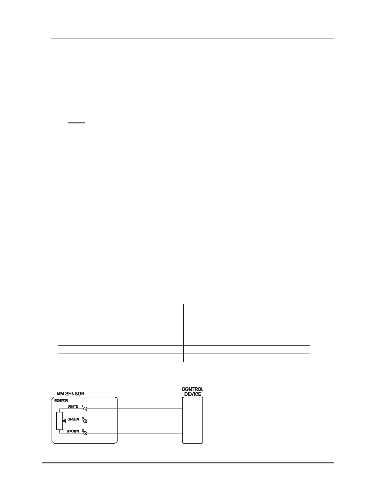
13.2 Wiring diagram resistance output sensor
Resistance value
increases
proportionally
with level
increase.
Resistance value
decreases
proportionally
with level
increase.
Signal
Models with cable white Brown Green
Models with box Clamp 1 Clamp 2 Clamp 3
Page 9
MM series
page 9 DT0593
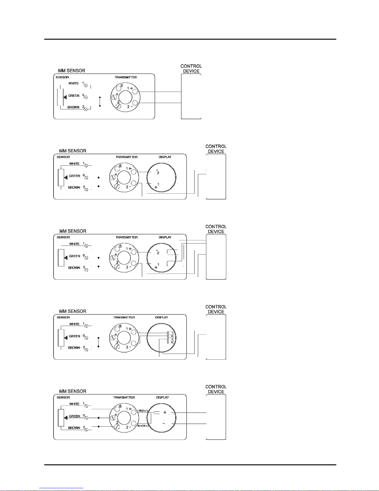
13.3 Wiring diagram with transmitter
13.4 Wiring diagram with touch screen LCD display type D
13.5 Wiring diagram with touch screen LCD display type R
13.6 Wiring diagram with LCD display type C
13.7 Wiring diagram with LED display type E
Page 10

MM series
page 10 DT0593
13.8 Electrical connection in intrinsically safe mode Ex ia
13.9 Electrical connection in explosion proof mode Ex d
Page 11

MM series
page 11 DT0593
14 Safety Instructions ( ATEX )
14.1 Area of validity
These security instructions apply to MM…E series magnetic level sensor for use in
explosion-proof atmospheres conforming to certificate LOM 06ATEX2054 X and
MM…F series conforming to CE certificate LOM 14ATEX2075 X
14.2 Guidelines.
These security instructions must be applied to the MM…E and MM…F series used in
gas explosion hazard environments.
It is necessary to follow carefully the instructions from the hazardous areas where the
MM...E or MM…F will be installed, as well as the safety instructions included in this
manual.
In models with transmitter and/or display the intrinsically safe specific parameters
are:
Ci total: Ci (sensor) + Ci (transmitter) + Ci ( display)
Li total: Li (sensor) + Li (transmitter) + Li ( display)
It must be considered the minimum value of Pi, Ii and Ui in all components used in the
assembly.
Temperature class and/or surface temperature relates solely to a device operated at
ambient temperature. On installation, the actual temperature class for process
operation has to be determined.
The maximum temperature in the enclosure head depends on the process
temperature and may not exceed the maximum service temperature indicated for the
junction box for the instruments MM…F series.
The guide tube must be mechanically protected or in locations with low risk of impact
for the instruments MM…F series.
When the tank inside is a zone 0, a degree of protection at least IP67 must be
ensured in the process connection for the instruments MM…F series.
Inlet bushing and cable glands must conform to the certification for their type in
accordance with the directive.
Models with cable must be protected with an external enclosure having at least a
degree of protection IP20 for MM…E series.
The use in zone 0 of heads made of aluminium should be restricted to locations
where the risk of ignition due to mechanical impact is not possible.
Page 12

MM series
page 12 DT0593
Verify that all data written in the label of the device matches the data required for the
installation.
Verify that there is no mechanical stress or deformation due to installation in the tank.
Remove power supply and verify that no explosion risk is present before opening
cover of the housing and check that the cover of housing is correctly mounted before
applying power to the instruments MM…F series.
The installation of instruments in hazardous areas must be exclusively done by
trained people.
14.3 Protection against ESD (electro static discharges)
Instruments with plastic parts that can produce electro statics discharges have a
label for it.
It is important to follow some rules to avoid ESD:
- Avoid rubbing the device.
- Never clean the device dry.
- Do not install the device near material airflows or near steam outlets.
14.4 Chemical resistance
Ensure that the device construction materials have chemical resistance sufficient to
prevent mechanical deformations that may affect the device.
14.5 Maintenance and repairs
The instrument does not require maintenance or servicing.
Repairs must be only carried out by Kobold Mesura (manufacturer).
14.6 Storage
Measuring instruments should be protected against humidity and dust.
Storage temperature: -5…+55ºC
Page 13

MM series
page 13 DT0593
15 Installation in hazardous zone
In classified zones, magnetic level switches series MM…E (intrinsically safe version),
can be installed in zone 0, 1, 2, 20, 21, 22 and series MM…F (explosion proof version)
can be installed in zone 0,1, 2, 21, 22.
Installation must be done by people trained regarding ATEX environments.
Intrinsically safe version Explosion proof version
16 ATEX Label Description
Page 14
MM series
page 14 DT0593
17 Declaration of conformity ATEX Ex ia
DECLARACIÓN DE CONFORMIDAD EU
EU DECLARATION OF CONFORMITY
EU-KONFORMITÄTSERKLÄRUNG
DÉCLARATION DE CONFORMITÉ
DICHIARAZIONE DI CONFORMITÀ EU
KOBOLD MESURA SLU
Avda. Conflent 68 nave 15 08915 Badalona (España)
Declara, bajo la propia responsabilidad, que el producto
Declares under our sole responsibility, that the product
Erklärt in alleiniger Verantwortung, dass das Produkt
Déclare sous sa seule responsabilité, que le produit
Dichiara sotto la propia responsabilità, che il prodotto
Liquid level transducer
MM-...E
A los cuales se refiere esta declaración, son conformes a las siguiente Directivas Europeas:
To which this declaration relates is in conformity with the following European Directives:
Mit folgenden Richtlinien konform ist:
À auxquels se réfère cette déclaration, ils sont conformes aux Directives Européennes suivant :
A ai quali si riferisce questa dichiarazione, sono conformi alle direttive europee seguente:
EMC2014/30/EU LVD2014/35/EU Atex2014/34/EU RoHS2011/65/EU
Normas armonizadas y documentos de la normativa aplicados:
Applied harmonised standards and normative documents:
Angewandte harmonisierte Normen und normativer Dokumente:
Normes harmonisées et documents normatifs appliqués
Norme armonizzate e documenti normativi applicati:
EN61010-1 :2011 EN60079-0:2012 (acc. EN60079-0:2013)
EN61000-6-2 :2006 EN60079-11:2012 (acc. EN60079-2013)
EN61326-1:2013
Certificado de examen CE de tipo Marcado
EC-type examination certificate Marking
EG-Baumusterprüfbescheinigung Kennzeichnung
Attestation d´examen CE de type Inscription
Certificazione per esame di tipo CE Marcatura
LOM06ATEX2054X
II 1 GD Ex ia IIC T6 Ga
-20 ºC ≤ Ta ≥ +60 ºC
Fabricado en
: KOBOLD MESURA SLU Avda. Conflent 68 nave 15 08915 BADALONA (Spain)
Made in:
Hergestellt in:
Fabriqué dans:
Fabbricato in:
Organismo notificado
: LOM 0163 Número notificación : LOM 05ATEX9070
Notified organism Notification number
Zertifizierungsstelle Zertifikatsnummer
Organization annoncée Nombre notification
Organismo informato Notifica di numero
Badalona june 2017 Gerente
DT0599
Page 15

MM series
page 15 DT0593
18 Declaration of conformity ATEX Ex d
DECLARACIÓN DE CONFORMIDAD EU
EU DECLARATION OF CONFORMITY
EU-KONFORMITÄTSERKLÄRUNG
DÉCLARATION DE CONFORMITÉ
DICHIARAZIONE DI CONFORMITÀ EU
KOBOLD MESURA SLU
Avda. Conflent 68 nave 15 08915 Badalona (España)
Declara, bajo la propia responsabilidad, que el producto
Declares under our sole responsibility, that the product
Erklärt in alleiniger Verantwortung, dass das Produkt
Déclare sous sa seule responsabilité, que le produit
Dichiara sotto la propia responsabilità, che il prodotto
Liquid level transducer
MM..F
A los cuales se refiere esta declaración, son conformes a las siguiente Directivas Europeas:
To which this declaration relates is in conformity with the following European Directives:
Mit folgenden Richtlinien Konform ist:
À auxquels se réfère cette déclaration, ils sont conformes aux Directives Européennes suivant :
A ai quali si riferisce questa dichiarazione, sono conformi alle direttive europee seguente:
EMC2014/30/EU LVD2014/35EU Atex2014/34/EU RoHS2011/65/EU
Normas armonizadas y documentos de la normativa aplicados:
Applied harmonised standards and normative documents:
Angewandte harmonisierte Normen und normativer Dokumente:
Normes harmonisées et documents normatifs appliqués
Norme armonizzate e documenti normativi applicati:
EN61010-1 :2011 EN60079-0:2012 (acc. EN60079-0:2013)
EN61000-6-2 :2006 EN60079-31:2009 (acc. EN60079-31:2016)
EN61326-1:2013 EN60079-1:2007 (acc. EN60079-1:2015)
EN60079-26:2007 (acc. EN60079-26:2015)
Certificado de examen CE de tipo
Marcado
EC-type examination certificate Marking
EG-Baumusterprüfbescheinigung Kennzeichnung
Attestation d´examen CE de type Inscription
Certificazione per esame di tipo CE Marcatura
LOM 14ATEX2075 X
II 1/2 G Ex d IIC T1..T6 Ga/Gb
II 2 D Ex t IIIC T410..T85ºC Db
Fabricado en: KOBOLD MESURA SLU Avda. Conflent 68 nave 15 08915 BADALONA (Spain)
Made in:
Hergestellt in:
Fabriqué dans:
Fabbricato in:
Organismo notificado
: LOM 0163 Número notificación : LOM 05ATEX9070
Notified organism Notification number
Zertifizierungsstelle Zertifikatsnummer
Organization annoncée Nombre notification
Organismo informato Notifica di numero
Badalona june 2017 Gerente
DT0607
Page 16

MM series
page 16 DT0593
19 Declaration of conformity
DECLARACIÓN DE CONFORMIDAD EU
EU DECLARATION OF CONFORMITY
EU-KONFORMITÄTSERKLÄRUNG
DÉCLARATION DE CONFORMITÉ
DICHIARAZIONE DI CONFORMITÀ EU
KOBOLD MESURA SLU
Avda. Conflent 68 nave 15 08915 Badalona (España)
Declara, bajo la propia responsabilidad, que el producto
Declares under our sole responsibility, that the product
Erklärt in alleiniger Verantwortung, dass das Produkt
Déclare sous sa seule responsabilité, que le produit
Dichiara sotto la propia responsabilità, che il prodotto
Liquid Level Transducer
MM
A los cuales se refiere esta declaración, son conformes a las siguiente Directivas Europeas:
To which this declaration relates is in conformity with the following European Directives:
Mit folgenden Richtlinien Konform ist:
À auxquels se réfère cette déclaration, ils sont conformes aux Directives Européennes suivant :
A ai quali si riferisce questa dichiarazione, sono conformi alle direttive europee seguente:
EMC2014/30/EU LVD2014/35/EU RoHS2011/65/EU
Normas armonizadas y documentos de la normativa aplicados:
Applied harmonised standards and normative documents:
Angewandte harmonisierte Normen und normativer Dokumente:
Normes harmonisées et documents normatifs appliqués
Norme armonizzate e documenti normativi applicati:
EN61010-1 :2011 EN61326-1:2013
EN61000-6-2 :2006
Fabricado en: KOBOLD MESURA SLU Avda. Conflent 68 nave 15 08915 BADALONA (Spain)
Made in:
Hergestellt in:
Fabriqué dans:
Fabbricato in:
Badalona june 2017 Gerente
DT0600
Page 17

MM series
page 17 DT0593
20 EC-TYPE CERTIFICATES
Page 18

MM series
page 18 DT0593
Page 19

MM series
page 19 DT0493
Page 20

MM series
page 20 DT0493
Page 21

MM series
page 21 DT0493
Page 22

MM series
page 22 DT0493
Page 23

MM series
page 23 DT0493
Page 24

MM series
page 24 DT0493
Page 25

MM series
page 25 DT0493
Page 26

MM series
page 26 DT0493
Page 27

MM series
page 27 DT0493
21 Notes
Page 28

MM series
page 28 DT0493
KOBOLD MESURA S.L.U
Avda. Conflent 68 nave 15
08915 Badalona
Tel.: +34 93 460 38 83
Fax: +34 93 460 38 76
E-Mail: info.es@kobold.com
www.kobold.com
Technical data
Subject to change without prior notice
 Loading...