

Page 1
Electromagnetic Flowmeter
measuring
•
monitoring
•
analyzing
MIS
●● Accuracy:
< ± (0.5% of Reading
+ 0.3% of Full Scale)
●● Monitoring, Transmitter
Function, and Batching
●● Bidirectional Measurement
●● p
: 230 PSIG; t
max
: 158 °F
max
●● Connection:
3" or 4" ANSI Flange
KOBOLD companies worldwide:
ARGENTINA, AUSTRALIA, AUSTRIA, BELGIUM, BULGARIA, CANADA, CHILE, CHINA, COLOMBIA,
CZECH REPUBLIC, EGYPT, FRANCE, GERMANY, HUNGARY, INDIA, INDONESIA, ITALY, MALAYSIA,
MEXICO, NETHERLANDS, PERU, POLAND, REPUBLIC OF KOREA, ROMANIA, SINGAPORE, SPAIN,
SWITZERLAND, TAIWAN, THAILAND, TUNISIA, TURKEY, UNITED KINGDOM, USA, VIETNAM
01/05-14-2019
KOBOLD Instruments, Inc.
1801 Parkway View Drive
Pittsburgh, PA 15205
Main Ofce:
1.800.998.1020
1.412.788.4890
info@koboldusa.com
www.koboldusa.com
Page 2

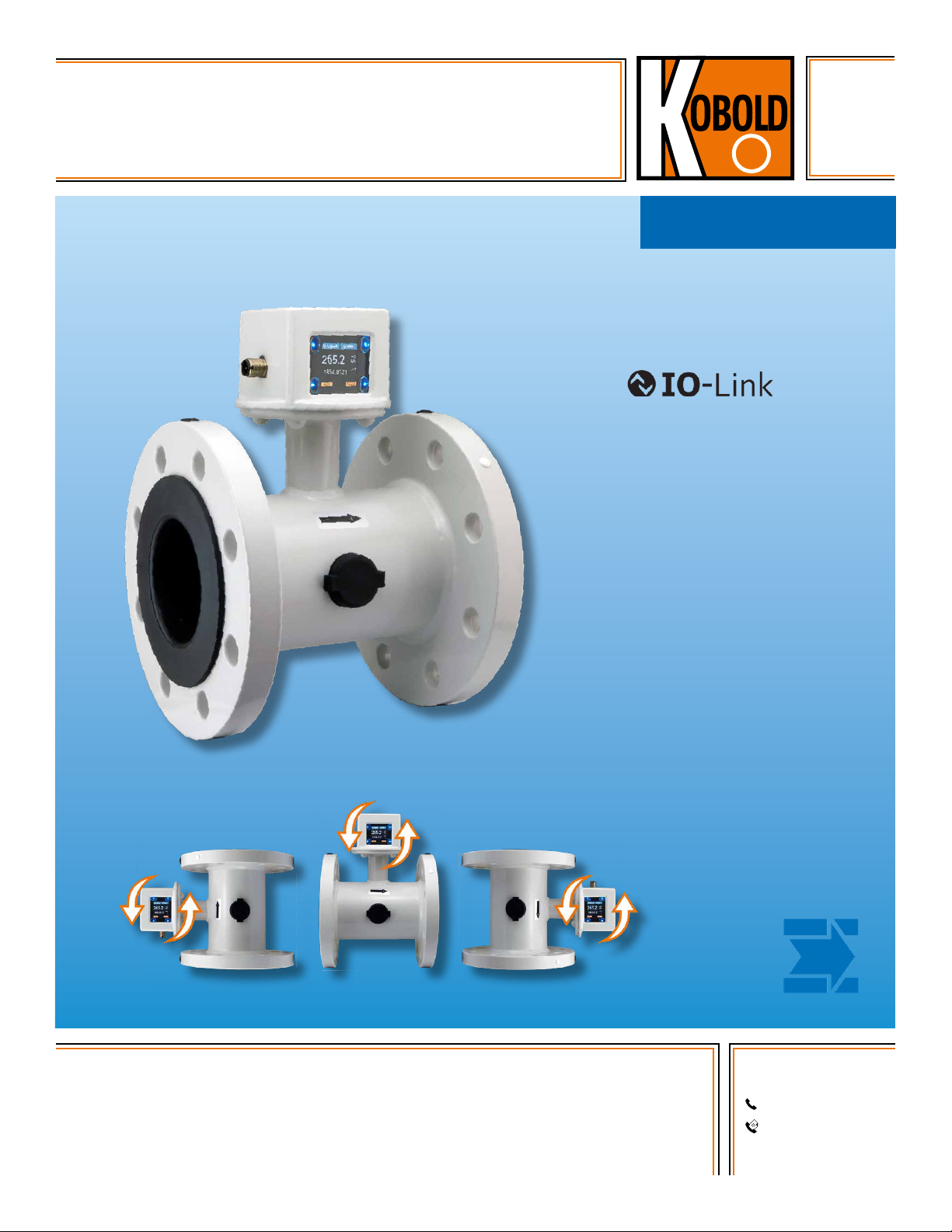
Electromagnetic Flowmeter Model MIS
Description
The new MIS electromagnetic flowmeter was developed for
measuring and monitoring medium-sized flow of conductive
liquids in pipes. The electromagnetic measurement principle is
as follows. According to Faraday’s Law of magnetic induction,
a voltage is induced in a conductor moving through a magnetic
field. The electrically conductive measuring agent acts as the
moved conductor. The voltage induced in the measuring agent
is proportional to the flow velocity and is therefore a value for
the volumetric flow. The flowing media must have a minimum
conductivity. The induced voltage is picked up by two sensing
electrodes which are in contact with the measuring agent and sent
to the measuring amplifier. The flow rate is calculated based on the
cross sectional area of the pipe.
The measurement does not depend on the process liquid and its
properties such as density, viscosity and temperature. The two
outputs can be independently set to switch, or provide an analog
or frequency output. A batching function can also be selected,
where output 1 is set to switch as NPN / PNP / PP and output 2 is
set as the control input.
Product Highlights
●● Monitoring, Batching and Transmitter Function
●● Batching Function has an External Control Input
●● Colored, Multi-parameter Configurable TFT-display, Rotatable in
90° Increments
●● Bidirectional Measurement
●● Intuitive Setup Menu via 4 Optical Touch Keys
●● 2 Configurable Outputs (Pulse/Frequency/Alarm
and Analog Output)
●● Grand and Resettable Totalizer
Common Application Areas
●● Water Treatment
●● Water Distribution Networks
●● Waste Water Treatment
●● Filtration Systems
●● Industrial Applications
Technical Details
Measurement Process: Electromagnetic
Range: See Flow Specific Values
Media: Conductive Liquids
Minimum Conductivity: ≥ 20 µS/cm
Max. Media Viscosity: 70 mm2/s
Max. Pressure: 230 PSIG
Accuracy:
<
± (0.5% of Reading + 0.3% of
Full Scale)*
Repeatability: ± 0.2% of Full Scale
Response Time Flow t90
(Alarm Output /
Pulse Output): < 250 ms
Mounting Position: Universal
Straight Piping
Requirement: 5x Upstream, 3x Downstream
Pressure Drop
(Max. at 3 m/s): 25 mbar
Programming: via 4 Optical Touch Fields,
Can be used with Gloves
Housing: Powder-coated Aluminum Body,
PMMA Display Screen
Connection: Steel (ASTM A105), Epoxy-coated
(Corrosivity Category C4M)
Wetted Parts
Lining: NBR (Others on Request)
Electrodes: Hastelloy® C276
Protection: IP 67
Media Temperature: 14…158 °F
Ambient Temperature: 14…140 °F
Electrical Specifications
Supply Voltage: 19 - 30 VDC, Internal Power Consumption,
Max. 200 mA
Display: TFT Display, 128 x 128 Pixels,
1.4" Display, Orientation Adjustable in 90°
Increments
Display Rate: 0.5...10 s, Adjustable
Pulse Output: Push-Pull, Freely Scalable, Configurable
for Partial and Accumulated Totalizer
Frequency Output: Push-Pull, Freely Scalable,
2 kHz @ Overflow
f
@ FS = 50 Hz
min
f
@ FS = 1000 Hz
max
Alarm Output: NPN, PNP, Push-Pull,
Configurable Max. 30 VDC, Max. 200 mA
Short-circuit Proof
Analog Output: Active, 3 wire, 0(4)-20 mA,
Max. Load 500 Ω or 0(2)-10 VDC,
(Ri = 500 Ω)
Control Input: Active Signal U
Max. 30 V
high
DC
0 <Low <10 VDC
15 VDC <High <Vs
Batching Function: Batching Output OUT2:
Push-Pull, High Active
Control Input OUT1:
START/STOP 0,5 s <t
RESET t
high
>5 s
high
<4 s
Electrical Conn: Plug M12x1, 4-pin
* Under Reference Conditions: Media Temperature: 59... 86 °F, 1 cSt, 500 µS/cm,
14.5 PSI, Ambient Temperature: 59...86 °F
2
www.koboldusa.com
No responsibility taken for errors;
subject to change without prior notice.
Page 3

Electromagnetic Flowmeter Model MIS
Flow Specific Values
ANSI Flange Measuring Range
3" 2.65...700 GPM
4" 4.40...1,100 GPM
Configuration of Outputs
Output 1 (OUT1, PIN 4) Output 2 (OUT2, PIN 2)
Analog Output 4-20 mA Analog Output 4-20 mA
Analog Output 0-20 mA Analog Output 0-20 mA
Analog Output 2-10 V Analog Output 2-10 V
Analog Output 0-10 V Analog Output 0-10 V
Switching Output NPN/PNP/PP Switching Output NPN/PNP/PP
Pulse Output PP Pulse Output PP
Frequency Output PP Frequency Output PP
Communication Mode M12 COM
Communication Mode IO-Link
Control Input
Control Input Batching Function Batching Output
IO-Link Specification
Manufacturer ID: 1105 (Decimal), 0 x 0451 (Hex)
Manufacturer Name: Kobold Messring GmbH
IO-Link Specification: V1.1
Bitrate: COM3
Minimal Cycle Time: 1.1 ms
SIO-Mode: Yes (OUT1 in Configuration IO-Link)
Block Parameterization: Yes
Operational Readiness: 10 s
Max. Cable Length: 65 feet
Electrical Connection MIS
OUT 2
2
1
4
3
OUT 1
No responsibility taken for errors;
subject to change without prior notice.
www.koboldusa.com
3
Page 4

Order Details (Example: MIS-H 208R 1 HH 100)
Electromagnetic Flowmeter Model MIS
Model
Material
1)
Lining
Flange Type/Size
Material Process
..208R.. = 3" ANSI, Class 150
MIS-.. ..H.. = Hard Rubber
..1.. = Steel, Epoxy-coated ..HH.. = Hastelloy
..210R.. = 4" ANSI, Class 150
1)
Possible linings available upon request: EPDM, soft rubber ,and PTFE
2)
Possible electrodes available upon request: platinum, stainless steel, tantalum, and titanium
Dimensions
1
x
2
1
h
M
Connection
Ø 3.94"
Ø10 0
Measuring and Grounding
Electrodes
2)
®
Transmitter
Mounting
..100 = Integrated
Flange
ANSI
150 lb
Weight
ANSI Flange
L
Nominal
Diameter
h L D s Dk d n
3" 6.98" 7.87" 7.48" 1.02" 6.00" 0.75" 0.157"
4" 7.29" 9.84" 9.06" 1.06" 7.50" 0.75" 0.315"
Pressure
Rating
Weight
3" Cl. 150 26.5 lbs
4" Cl. 150 34.4 lbs
d
D
s
n
Dk
4
www.koboldusa.com
No responsibility taken for errors;
subject to change without prior notice.
Page 5

Electromagnetic Flowmeter Model MIS
Measuring Mode, Display Layout "Single" Configurable
OUT1 configured as 4-20 mA OUT2 disabled
and assigned to flow
Display area for output status
Font White: MV* within FS
Font Yellow: 100% FS <= MV* <= OvFlow
Font Red: MV* > OvFlow
Measuring variable with sign for direction
Key symbol 1
(Menu functions)
* Measured Value
Q4-20mA
0.000
+Q
Measuring Mode, Display Layout "Dual" Configurable
OUT1 configured as switching output OUT2 configured as switching output
Push-Pull and assigned flow PNP and assigned to volume
Q SW+-
Font White: MV within FS
Font Yellow: 100% FS <= MV <= OvFlow
Font Red: MV > OvFlow
0.850
87654321
OFF
LPM
INFO
Key symbol 2
(Options INFO)
AC SW+
+Q
L/m
+AC
L
INFO
Configurable Variables
Flow Rate Q
Volume AC
Part Volume PT
4 digits + decimal point
Unit for measuring variable
Configurable Variables
for Both Displays
Flow Rate Q
Volume AC
Part Volume PT
Measuring variables
with sign for direction
Unit for measuring variable
OUT1 configured as Pulse output OUT2 configured as analog output
Push-Pull and assigned to Part Volume 4-20 mA and assigned to flow rate
PT PLS
12345678
0.850
No responsibility taken for errors;
subject to change without prior notice.
Q 4-20 mA
+PT
L
+Q
L/m
INFO
5
www.koboldusa.com
 Loading...