

Page 1
Operating Instructions
for
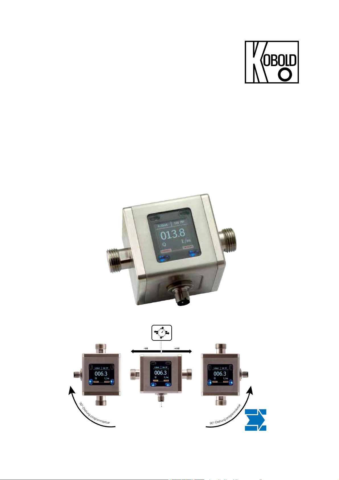
Electromagnetic Flowmeter
Model: MIM
Page 2

MIM-
We don’t accept warranty and liability claims neither upon this publication nor in
case of improper treatment of the described products.
The document may contain technical inaccuracies and typographical errors. The
content will be revised on a regular basis. These changes will be implemented in
later versions. The described products can be improved and changed at any time
without prior notice.
© Copyright
All rights reserved.
1. Contents
1. Contents ........................................................................................................ 2
2. Note .............................................................................................................. 4
3. Instrument Inspection .................................................................................... 4
4. Regulation Use .............................................................................................. 4
5. Environment .................................................................................................. 5
6. Operating principle ........................................................................................ 5
6.1 General ................................................................................................ 5
6.2 Minimum electrical conductivity / gas bubbles ..................................... 5
6.3 Deposits ............................................................................................... 6
6.4 Measuring electrodes........................................................................... 6
7. Mechanical connection .................................................................................. 7
7.1 Check operating conditions .................................................................. 7
7.2 Installation ............................................................................................ 7
8. Electrical Connection .................................................................................... 9
8.1 General ................................................................................................ 9
8.2 Pin assignment .................................................................................. 10
9. Operation and menu structure .................................................................... 11
9.1 General .............................................................................................. 11
9.2 Measuring mode ................................................................................ 12
9.3 Menu Mode ........................................................................................ 15
10.Device configuration .................................................................................... 16
10.1 Sequence of device parameterization ................................................ 16
10.2 Overview of the menu functions / device parameters ........................ 17
10.3 Display ............................................................................................... 20
10.4 Measurement ..................................................................................... 20
10.5 Outputs .............................................................................................. 23
10.6 User service ....................................................................................... 27
10.7 Service / Factory service .................................................................... 28
10.8 Information ......................................................................................... 28
10.9 Device default settings ....................................................................... 29
11.Technical Information .................................................................................. 30
12.Order Codes ............................................................................................... 31
13.Dimensions ................................................................................................. 32
14.EU Declaration of Conformance .................................................................. 33
page 2 MIM K02/1217
Page 3

MIM-
Manufactured and sold by:
Kobold Messring GmbH
Nordring 22-24
D-65719 Hofheim
Tel.: +49(0)6192-2990
Fax: +49(0)6192-23398
E-Mail: info.de@kobold.com
Internet: www.kobold.com
MIM K02/1217 page 3
Page 4

MIM-
2. Note
Please read these operating instructions before unpacking and putting the unit
into operation. Follow the instructions precisely as described herein.
The devices are only to be used, maintained and serviced by persons familiar
with these operating instructions and in accordance with local regulations
applying to Health & Safety and prevention of accidents.
When used in machines, the measuring unit should be used only when the
machines fulfil the EC-machine guidelines.
as per PED 2014/68/EU
In acc. with Article 4 Paragraph (3), "Sound Engineering Practice", of the PED
2014/68/EU no CE mark.
Diagram 8, Pipe, Group 1 dangerous fluids
3. Instrument Inspection
Instruments are inspected before shipping and sent out in perfect condition.
Should damage to a device be visible, we recommend a thorough inspection of
the delivery packaging. In case of damage, please inform your parcel service /
forwarding agent immediately, since they are responsible for damages during
transit.
Scope of delivery:
The standard delivery includes:
Electromagnetic Flowmeter model: MIM
Operating Instructions
4. Regulation Use
The MIM flowmeter has been specially developed for the measurement, display
and transmission of both, flow rates and temperature of conductive liquids. The
instrument has a graphic TFT display, rotatable in 90 ° steps and can display flow
rate, temperature, daily volume counter (resettable) and total volume counter in
the units of measurement selected by the operator. A clear menu guides the user
through the parameterization of the device, which largely eliminates the need to
look into the operating instructions.
Any use of the magnetic flowmeter, model: MIM, which exceeds the
manufacturer’s specification, may invalidate its warranty. Therefore, any resulting
damage is not the responsibility of the manufacturer. The user assumes all risk
for such usage.
page 4 MIM K02/1217
Page 5

MIM-
5. Environment
The MIM device with stainless steel housing and stainless steel electrodes is
weatherproof and conforms to protection class IP67. The meter is designed for
harsh indoor or outdoor environments and complies with Directive 2014/30/EU
(Electromagnetic Compatibility).
6. Operating principle
6.1 General
The new KOBOLD MIM Flowmeter is designed to measure and monitor small
and medium flows of conductive fluids in piping.
The device works on the magnetic-inductive measuring principle. According to
Faraday's law of induction, a voltage is induced in a conductor moving in a
magnetic field. The electrically conductive measuring medium corresponds to the
moving conductor in the process. The voltage induced by the measuring medium
is proportional to the flow rate and thus a measure of the volume throughput.
Prerequisite is a minimum electrical conductivity of the flowing medium. The
induced voltage is fed to a measuring amplifier via two electrodes, which are in
conductive contact with the medium. The volume flow is calculated via the
defined pipe diameter.
The measurement is independent of the medium and its physical properties such
as density, viscosity and temperature. The device can be configured via the
display. There are two outputs available, which can each be configured as alarm,
frequency, pulse, voltage, and current outputs.
The device also provides a dosing function. The dosing function can be activated
in measuring mode via the four buttons. The dosing function controls simple filling
tasks and also measures flow rate and partial amount.
6.2 Minimum electrical conductivity / gas bubbles
For the correct function of the instrument, it is necessary that the flow channel is
always completely filled with medium. From a minimum electrical conductivity of
20 μS / cm, the MIM operates within the specified error limits. The conductivity of
the medium is constantly monitored by the device electronics. If the electronics
detects that the minimum conductivity has fallen below min. value, this is signaled
by displaying the error message 'Empty pipe' and the flow rate reading is set to
'0'. Air bubbles in the flowing medium or media with varying conductivity in the
range of the minimum conductivity can disturb the measuring function and reduce
the measuring accuracy of the MIM. Gases contained in the liquid are also
measured as a volume flow and lead to measurement errors. If necessary, install
appropriate vents in the flow of the unit.
MIM K02/1217 page 5
Page 6

MIM-
6.3 Deposits
Minor deposits on the measuring tube generally do not affect the measuring
accuracy unless their conductivity deviates significantly from the liquid. For liquids
that have a tendency to deposit, periodically inspect the meter tube and, if
necessary, clean it.
6.4 Measuring electrodes
The MIM uses electrodes with galvanic tapping. They are in direct contact with
the medium. The standard electrodes are made of stainless steel 1.4404.
page 6 MIM K02/1217
Page 7
MIM-
7. Mechanical connection
7.1 Check operating conditions
flow rate
max. operating pressure
max. operating temperature
In general, MIM is subjected to the same loads as the piping into which it is
installed. The MIM should therefore be kept away from extreme loads, such as
pressure surges with strong, dynamic pipe movements, vibrations in the proximity
of centrifugal pumps, high temperature media, flooding etc.
7.2 Installation
Remove all packing materials and transport retainers and ensure that no such
materials remain in the device.
It can be installed in vertical, horizontal or rising pipes. Flow in direction of the
arrow.
Avoid pressure and tensile load.
Mechanically secure the inlet and outlet pipe at a distance of 50 mm from the
connections.
Avoid valves or large reduction on the inlet section (this increases the
inaccuracy of measurements).
Check the leak tightness of the connections.
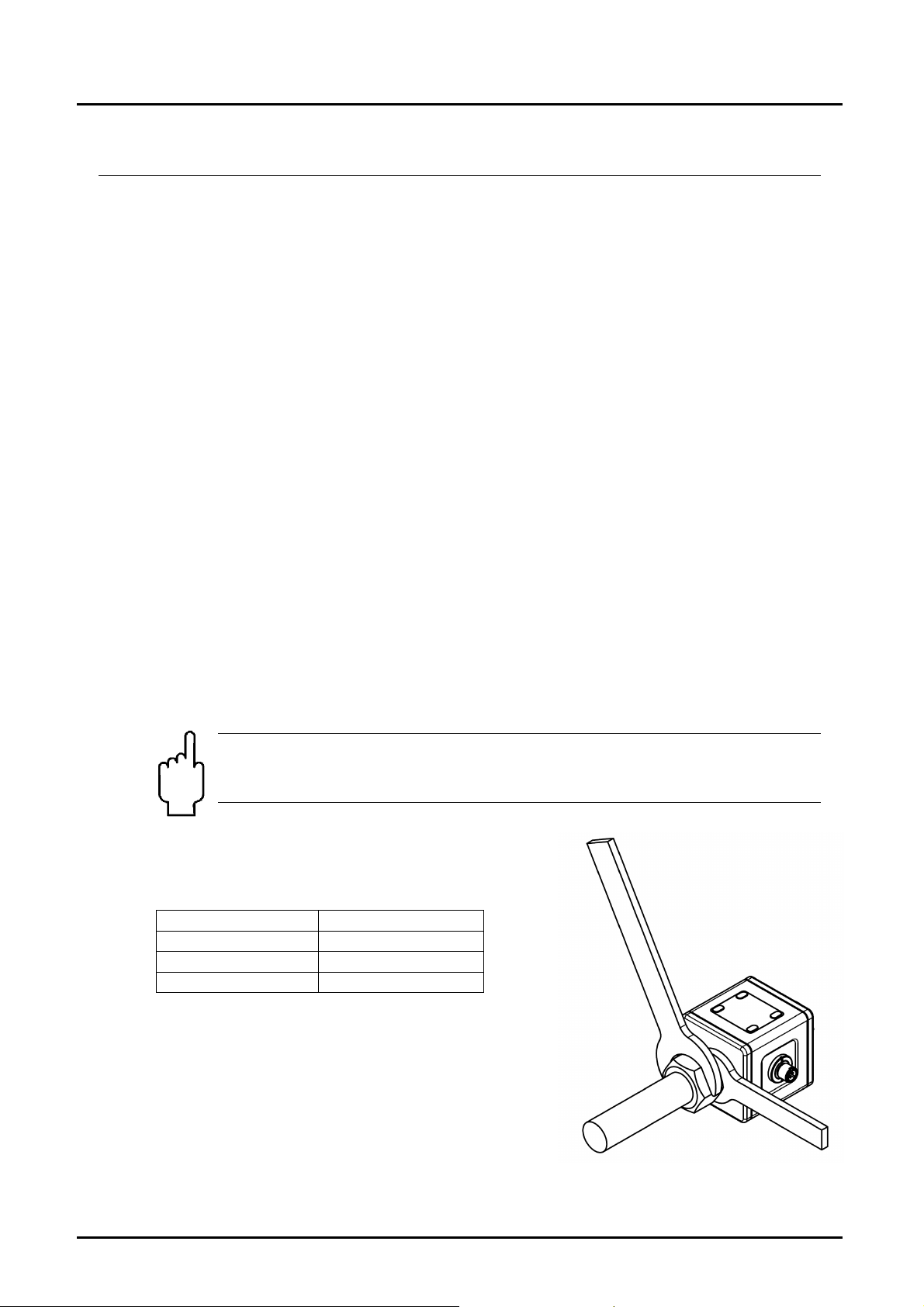
While mounting MIM hold the flowmeter from spanner surface (not
from the housing) with the help of spanner.
Take into account the tightening torque.
Nominal size Tightening torque
½“ 22 to 24 Nm
¾“ 28 to 30 Nm
1“ 28 to 30 Nm
MIM K02/1217 page 7
Page 8

MIM-
Inlet and outlet run
Installation from top to bottom avoid these installation locations
Gas bubbles,
particle
Free outlet
page 8 MIM K02/1217
Page 9

MIM-
8. Electrical Connection
8.1 General
Attention! Make sure that the voltage values of your system
correspond with the voltage values of the measuring unit.
Make sure that the supply wires are de-energised.
Connect the supply voltage and the output signal to the plug PIN’s as stated
below.
We recommend the use of wires with cross sectional area of min. 0.25 mm².
Attention! The measuring electrodes are galvanically connected
with the reference potential of the supply voltage and the signal
output.
MIM K02/1217 page 9
Page 10
MIM-
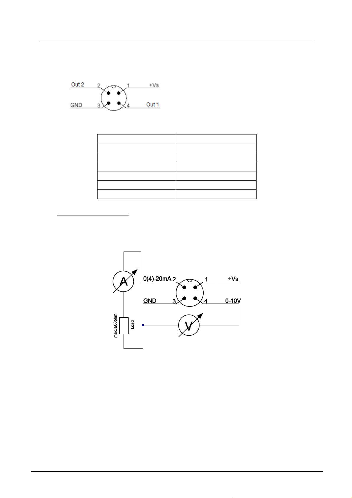
8.2 Pin assignment
Configurable output functions:
analogue output 4-20 mA analogue output 4-20 mA
analogue output 0-20 mA analogue output 0-20 mA
analogue output 0-10 V analogue output 0-10 V
alarm output alarm output
pulse output pulse output
frequency output frequency output
Connection example:
OUT2: analogue output 4-20 mA
OUT1: analogue output 0-10 V
Out 1 Out 2
page 10 MIM K02/1217
Page 11

MIM-
9. Operation and menu structure
9.1 General
9.1.1 Operation of the optical buttons
Deactive optical button
Optical button active
An optical button is located at each corner of the TFT display. The operability of
the respective buttons is signaled by blue backlighting; therefore non-backlit
buttons are disabled and cannot be operated. To operate the keys, the finger
must be placed on the key-dome and raised again. The orange background of the
button symbols is briefly displayed in blue as visual feedback for a detected key
press.
To avoid accidental operation in measuring mode, the operator must hold down
the menu button for 3-5 seconds to activate the function. If the menu button is
held down for more than 3 seconds, the blue backlighting will begin to flash to
alert the user to release the button.
The operation of the optical buttons can also be done with gloves or other
optically reflective objects, light dirt on the surface usually does not interfere with
the key function.
9.1.2 Function of the control buttons
The function of each control key can be recognized by the respective symbol
displayed in the corners of the TFT display.
key symbol designation
menu mode
info display
down -
Measuring mode menu mode
Activate menu
mode
hold 3-5 sec.
opens the info
menu
function
-
-
Scroll down menu /
decrease numeric
value when entering
numeric value
MIM K02/1217 page 11
Page 12

MIM-
key symbol designation
up -
forward -
backward -
Measuring mode menu mode
function
Menu scroll up /
Increase the number
value for numeric
value input
Menu level lower /
forward (last menu
level: Save value)
Menu function: menu
level higher / back
(last step: exit menu)
9.2 Measuring mode
After applying the supply voltage, the device starts in measuring mode. In this
mode, the measured values of the respective measuring variables are
continuously recorded; the current instantaneous flow values, temperature values
and the volume counter readings are cyclically calculated and displayed
according to the type of display.
In addition to the main display, the states and configuration of the outputs are
shown in the display. If the corresponding output is configured as an alarm
output, the status is also displayed with a green or red background color. If the
background color is green, the set threshold value is exceeded; if it is red, the
current value is still under threshold.
page 12 MIM K02/1217
Page 13

MIM-
Measurement Mode Display Layout 'Single'
The measurement variables are represented by their corresponding symbols:
The outputs and their status are shown on the display as follows:
The measured variables flow, temperature and volume counter can in principle be
assigned to each output function. The assignment of the respective output is
indicated by the display of the symbol of the measuring variable. The
representation of the assignment is independent of the set display layout (single,
dual).
MIM K02/1217 page 13
Page 14

MIM-
Measurement Mode Display Layout 'Dual'
9.2.1 Display area of the flow meters
The number of digits displayed on the volume counter display (partial and total
volumetric counters) is limited to max. 8 digits. The partial and total volumetric
meters therefore have a smaller font size than the flow and temperature display.
If the 8-digit display range of the meter is exceeded, this is indicated by the
display of 8 minus characters (--------). In this case, the meter reading can no
longer be read. The user now has the option of bringing the counter reading back
into the display area by changing the volume counter unit.
page 14 MIM K02/1217
Page 15

MIM-
9.3 Menu Mode
In menu mode, all device parameters can be set. The individual parameters are
arranged in menu groups by function. While the menu mode is activated, the
signal processing and the outputs are still active in the background. However, all
display parameters and outputs are updated after exiting the menu mode or in the
measuring mode.
Note: The menu mode will not exit automatically after a certain time
without using the buttons. The menu mode remains active until the user
presses the button to the measuring mode.
9.3.1 Parameter setting
9.3.1.1 List Selection
Parameters with predefined selection values are defined by means of list
selection. The currently selected menu item is displayed in orange text. The
selection can be moved with the keys, the key
is used to accept the selection.
To activate the menu mode, press the button for 3-5 seconds. The
parameters are divided into main groups and subgroups.
The buttons are used to select the main groups. In the main menu
not all menu groups can be shown on the display at the same time, the list of
individual menu items then scrolls up or down when the selection has reached
the top or bottom. To choose the selection, the key is pressed and the
device jumps to the corresponding submenu or parameter setting level. For
selection of predefined parameter values and are
used. After changing the value of the parameter and confirming with the
parameter is saved and the return to the higher menu level. To return to the main
menu or to exit the menu mode, press (repeatedly) .
MIM K02/1217 page 15
Page 16

MIM-
9.3.1.2 Numerical value input
When setting parameters with a numerical value, the assigned unit is always
displayed below the input field in square brackets in the input function. The
maximum size and the number of decimal places are fixed and cannot be
changed. After calling the input function, first the left, outer digit is displayed in
orange. This position can now be adjusted either with the keys in
the value from 0 to 9. By pressing the key , the entry point moves to the
right and the next digit can be changed. By pressing the key , the editing
point can be moved to the left again. If the editing point is on the far right, the set
value is saved by pressing the key again and switched to the higherlevel menu function.
10. Device configuration
10.1 Sequence of device parameterization
The flowmeter MIM is pre-configured in factory. Changing the parameters
"Measuring range" and "Sensor constant" or "K factor" is therefore not permitted.
The adjustment of these parameters is only possible on the part of Koboldfactory.
In the event of subsequent changes to volume or throughput units, the dependent
parameters are converted and adjusted accordingly. However, the limit
parameters of the switching outputs must always be checked and adjusted
manually when adjusting volume or throughput units - these are not automatically
converted.
An accidental change of the parameterization can be revised by the function
"Reset factory setting" in the menu Service / User menu / Factory setting.
page 16 MIM K02/1217
Page 17

MIM-
10.2 Overview of the menu functions / device parameters
The Kobold flowmeter MIM gives user the opportunity to make the
parameterization easily via the settings menu. In the following table, the menu
structure is structured by level. Using this table, each parameter and function of
the device can be set and configured.
Menu
level
Display
Measurement
Sublevel
Refresh
Orientation
Layout
Display value
Flow
Volume
Temperature Unit List selection
Part Volume
Parameter
level
[sec]
rotate CW
rotate CCW
Single
Dual
Upper display List selection
Lower display List selection
Unit List selection sets flow units
Cut off numerical input
Counting type
Unit List selection sets volume units
Counting type
Unit
Memory reset Yes/No
Subparameter
level 1
n.A.
absolute/
bidirectional
absolute/
bidirectional
List selection
Sub-
parameter
level 2
n.A. n.A.
Sub-
parameter
level 3
Description Value range
Sets display refresh
rate
rotates the display
90° clockwise
rotates the display
90° counter
clockwise
shows only one
input variable on
the main display
shows two input
variables on the
main display
variable to be
displayed on main
or upper display
variable to be
displayed on lower
display
suppresses flow
below this value
sets the counting
method for
accumulated
totalizer
sets temperature
units
sets the counting
method for partial
totalizer
sets volume units
resets partial
totalizer
0.5-10 0.5 sec
n.A n.A
n.A n.A
(Variables depend on
the type of sensor
connected. For MIM 4
Variables available i.e.
Flow, Volume,
Temperature, Part
volume)
ml/m, L/m, L/h, m3/h,
galUS/m, galUS/h,
galUK/m, galUK/h, User
0 ≤ Value ≤ M. range
start
n.A. absolute
ml, L, m3, galUS,
galUK, User
°C, °F, User
n.A. absolute
ml, L, m3, galUS,
galUK, User
n.A. n.A
Default
value
n.A
L/m
0.04
L
°C
L
MIM K02/1217 page 17
Page 18

Menu
level
Output 1/
Output 2
MIM-
Sublevel
Hier wird erst
die Variable
ausgewählt,
die
ausgegeben
werden sollte
The user is
supposed to
select the
variable he
wants to give
out as output
Parameter
level
Flow
Volume Pulse output
Subparameter
level 1
Alarm Output
4-20 mA
0-20 mA
0-10 V
Frequency
output
parameter
Function
Output Type sets characteristic
Switch
Function
Threshold
Hysteresis
Suppression
factor
Value for
4 mA
Value for
20 mA
Value for
0 mA
Value for
20 mA
Value for 0 V
Value for
10 V
max.
Frequency
Overflow
Value for
0 Hz
Value for max
Hz
Pulse unit
Pulse volume
Pulse width
Sub-
level 2
Sub-
parameter
level 3
List
selection
numerical
input
List
selection
numerical
input
Description Value range
sets function of
alarm output
of output
sets switching
function
sets threshold
sets hysteresis
switching delay
factor
sets variable value
for 4mA
sets variable value
for 20mA
sets variable value
for 0mA
sets variable value
for 20mA
sets variable value
for 0V
sets variable value
for 10V
sets max.
frequency to be
given out at Full
scale
sets overflow in %
of max.freq
sets variable value
for 0Hz
sets variable value
for max Hz
sets volume units
for Pulse volume
sets volume
represented by one
pulse
sets width of each
pulse
Limit/Window Limit
NPN/PNP/PP NPN
NO/NC
M. range start ≤ Value
≤ M. range End
-9999,0 ≤ Value ≤
+9999,0
0 ≤ Value ≤ 60
M. range start ≤ Value
< Value for 20 mA
Value for 4 mA <Value
≤ M. range End
M. range start ≤ Value
< Value for 20 mA
Value for 0 mA <Value
≤ M. range End
M. range start ≤ Value
< Value for 10 V
Value for 0 V <Value ≤
M. range End
50-1000 Hz 500 Hz
1-100 1%
M. range start ≤ Value
< Value for 0 Hz
Value for 0 Hz <Value ≤
M. range End
ml, L, m3, galUS,
galUK, User
0-999 1 L
1-20000 1ms
Default
value
NO
1 L/m
1 L/m
0
0 L/m
100 L/m
0 L/m
100 L/m
0 L/m
100 L/m
0 L/m
100 L/m
L
page 18 MIM K02/1217
Page 19

MIM-
Menu
level
User
Service
Factory
Service
Device
Status
Sublevel
Change
Password
Factory reset Yes/No
Lock Menu
Parameter
Temperature
Part volume Pulse output
numerical input
Lock/Unlock
level
Subparameter
level 1
Alarm Output
4-20 mA
0-20 mA
0-10 V
Frequency
output
Sub-
parameter
level 2
Function
Output Type sets characteristic
Switch
Function
Threshold
Hysteresis
Suppressionf
actor
Value for
4 mA
Value for
20 mA
Value for
0 mA
Value for
20 mA
Value for 0 V
Value for
10 V
max.
Frequency
Overflow
Value for
0 Hz
Value for max
Hz
Pulse unit
Pulse volume
Pulse width
n.A.
Password protected
Kobold Logo with Firmware version
Sub-
parameter
level 3
List
selection
numerical
input
List
selection
numerical
input
Description Value range
sets function of
alarm output
of output
sets switching
function
sets threshold
sets hysteresis
switching delay
factor
sets variable value
for 4 mA
sets variable value
for 20 mA
sets variable value
for 0 mA
sets variable value
for 20 mA
sets variable value
for 0 V
sets variable value
for 10 V
sets max.
frequency to be
given out at Full
scale
sets overflow in %
of max.freq
sets variable value
for 0Hz
sets variable value
for max Hz
sets volume units
for Pulse volume
sets volume
represented by one
pulse
sets width of each
pulse
protects user
service with
password if it is set
other than 00000
sets all the settings
to factory settings
locks the menu
entry using same
password as set
under 'Change
Password'
Limit/Window Limit
NPN/PNP/PP NPN
NO/NC
M. range start ≤ Value
≤ M. range End
-9999,0 ≤ Value ≤
+9999,0
0 ≤ Value ≤ 60
M. range start ≤ Value
< Value for 20 mA
Value for 4 mA <Value
≤ M. range End
M. range start ≤ Value
< Value for 20 mA
Value for 0 mA <Value
≤ M. range End
M. range start ≤ Value
< Value for 10 V
Value for 0 V <Value ≤
M. range End
50-1000 Hz 500 Hz
1-100 1%
M. range start ≤ Value
< Value for 0 Hz
Value for 0 Hz <Value ≤
M. range End
ml, L, m3, galUS,
galUK, User
0-999 1 L
1-20000 1ms
00000-99999 00000
Default
value
NO
1 L/m
1 L/m
0
0 L/m
100 L/m
0 L/m
100 L/m
0 L/m
100 L/m
0 L/m
100 L/m
L
n.A.
n.A.
Unlock
MIM K02/1217 page 19
Page 20

MIM-
10.3 Display
10.3.1 Refresh
Parameter "Refresh" defines the time interval within which the measuring
variables are displayed. The state of the outputs (current output, voltage output,
frequency output) is also recalculated after the measuring time has expired.
The "Refreshrate" can be increased in steps of 0.5 sec. to 10 sec. An increase in
the refresh rate time causes on one hand an increased "filtering" of the input
signals, but also an increased reaction time for the outputs.
10.3.2 Orientation
With the menu item "Orientation" the display can be rotated either clockwise or
counterclockwise in 90 ° increments. As the display rotates, both the display
contents and the function of the 4 control buttons are turned.
10.3.3 Layout
This parameter can be used to configure the display to either show one
measurement variable or two measurement variables.
10.3.4 Display value
With the aid of this parameter, the measurement variables provided by the
transmitter can be displayed. Depending on the 'Layout' display, either one or two
measuring variables can be displayed.
10.4 Measurement
The Measurement menu lists the measurement variables that the transmitter
provides. For magnetic inductive flowmeter, these are:
• Flow
• Volume (total volume counter)
• Temperature
• Part volume
Each measurement variable is still divided into its own submenu. In the submenu,
all parameters relating to the respective measuring variables can be adjusted.
page 20 MIM K02/1217
Page 21

MIM-
10.4.1 Flow
10.4.1.1 Unit
The displayed unit for the flow measurement can be selected from various
predefined standard units. It is also possible to define a user-defined unit ("user"),
here the "user unit" must be in liters / min. be programmed.
e.g. Unit User = 100 LPM, if Q = 500 LPM then the display shows 5 users.
10.4.2 Volume
10.4.2.1 Counter type
Absolute:
Regardless of the flow direction, the calculated partial volume is added to the
counters.
Bidirectional:
Depending on the flow direction, the calculated partial volume is added or
subtracted to the counters. If the measured flow value is negative, the volume
value goes down from measurement to measurement (possibly into the negative
range).
10.4.2.2 Volume unit
The parameter "Volume unit" defines the volume unit of all volume meters. The
listed volume units are available. When changing the volume unit, the current
counter readings are converted to the new volume unit.
MIM K02/1217 page 21
Page 22

MIM-
10.4.3 Temperature
10.4.3.1 Unit
The displayed unit for the temperature measurement can be selected from
various default units. It is also possible to define a user-defined unit ("user"), in
which case the "user unit" must be programmed in ° C.
e.g. Unit user = 50 ° C, if T = 50 ° C then the display shows 1 user.
10.4.4 Part Volume
10.4.4.1 Counter type
Absolute:
Regardless of the flow direction, the calculated partial volume is added to the
counters.
Bidirectional:
Depending on the flow direction, the calculated partial volume is added or
subtracted to the counters. If the measured flow value is negative, the volume
value goes down from measurement to measurement (possibly into the
negative range).
10.4.4.2 Volume unit
The parameter "Volume unit" defines the volume unit of all volume meters. The
listed volume units are available. When changing the volume unit, the current
counter readings are converted to the new volume unit.
10.4.4.3 Memory reset
In this menu, the part quantity counter can be reset.
page 22 MIM K02/1217
Page 23

MIM-
10.5 Outputs
The MIM flowmeter provides a total of 2 outputs that are freely configurable. The
configuration of the outputs (output 1 and output 2) is done via a wizard function.
The wizard function guides the user step by step through all necessary settings.
Steps:
• Select output
• Selection of the source or the measurement variable to be output (Flow,
Volume, Temperature, Part volume)
• Selection of an output type (4-20 mA, 0-20 mA, 0-10 V, alarm, pulse,
frequency output)
• Setting the output (scaling, thresholds)
• Save the configuration
10.5.1 Alarm output
The alarm outputs can be parameterized with a limit value function or a window
function.
10.5.1.1 Function
The parameter "Function" defines the basic function. Limit value function and
window function are available.
Limit value function: The switching output is active if the current flow rate value is
above the switching threshold. It remains active until the measured value has
fallen below the switching threshold minus the hysteresis.
MIM K02/1217 page 23
Page 24

MIM-
Window function: The switching output is active if the current flow measured
value is outside a window, which is formed by the "switching threshold" and the
"lower threshold". The monitored window decreases in each case by the amount
of the "hysteresis". If the switching output is to be active within the window, the
parameter "switching function" must be changed from N/O to N/C.
10.5.1.2 Output type
The parameter "Output type" defines the function of the transistor output. NPN,
PNP or PP (push-pull) output types are available. The push-pull type combines
NPN and PNP and is therefore the best choice for most circuits. All outputs are
short circuit and overload protected.
10.5.1.3 Switching function
The "switching function" defines the mode of operation of the outputs. In the
default setting "normally open", the output becomes active (switched) when the
measured value exceeds the switching threshold. This feature is also referred to
as N.O.
In the "Normally closed" setting, the output below the switching threshold is
already active and is deactivated when the measured value exceeds the
switching threshold. This function is also referred to as N.C.
10.5.1.4 Threshold
Threshold for limit value function and upper window point for window function.
10.5.1.5 Lower threshold
The "lower threshold" defines the lower limit when using the window function.
When using the limit value function, this parameter remains ineffective.
The switching thresholds can be set both positive and negative. The setting of the
negative switching thresholds is used for "A-B" function, whereby the flow
indicator can be negative. When changing the input type, the switching thresholds
must be checked again and corrected if necessary.
page 24 MIM K02/1217
Page 25

MIM-
10.5.1.6 Hysterese
The appropriate setting of the "hysteresis" parameter ensures that the switching
outputs do not switch on and off continuously when the current measured value
fluctuates around the switching threshold. The hysteresis value should therefore
always be greater than the real measured value fluctuations. As a result, a
targeted suppression can be achieved.
10.5.1.7 Interference suppression factor
Further suppression of the switching outputs of fluctuating measuring signals can
be achieved by setting the parameter "Suppressor factor". If this parameter is
selected greater than one, then the switching threshold must be exceeded in
succession with the frequency of the set value before the corresponding
switching output is activated. With this function, sporadic limit overruns can be
safely suppressed. However, the response time increases according to the level
of the "suppression factor".
It is also possible to use the switch outputs with "limit function" for "direction
detection". To do this, the "Input type" in the "Signal input" menu must be set to
"Direction detection". In this case, both the "switching threshold" and the
"hysteresis" must be set to '0'. When changing direction, the switching output
switches depending on the "switching function".
10.5.2 Analogue outputs
10.5.2.1 Current output 0(4)-20 mA
The current output gives a measured variable (flow or temperature) in scaled
form as a 0 (4) -20 mA current signal.
Flow rate for 20 mA
The current output is scaled via the "Value for 20 mA "and" Value for 4 mA "(with
current output 0-20 mA" Value for 0mA "). By default, the "Value for 20mA"
parameter is set to the value for the end of the measuring range, but can be
parameterized as desired within the measuring range, but always >> as the
measuring range start value. The parameters "Value for 4mA" / "Value for 0mA"
define the measured values for the starting current value, which may also be set
freely in the measuring range.
Note 1: If the value is set smaller than the end of the measuring range, the
resolution and accuracy of the output voltage value are reduced.
MIM K02/1217 page 25
Page 26

MIM-
10.5.3 Pulse output
The MIM flowmeter provides a scalable pulse output. When the pulse output is
activated, the incoming volume is converted to the output pulse train. The pulse
width of the output pulse is adjustable in the range of 1 ms to 20,000 ms.
The electrical output type of the pulse output is push-pull, therefore HIGH and
LOW are actively switched through at the output.
Behavior on OVERFLOW:
If the volumetric flow measurement is in the OVERFLOW range, the pulse output
is switched off and a constant HIGH level is applied to the output.
Generation of the output pulse train:
The maximum adjustable pulse rate at the pulse output is 1000 pulses per liter.
That the minimum pulse volume that can be represented with the pulse output is
0.001 L per pulse. Furthermore, the set pulse volume must fulfill the following
condition:
Measuring range end
If the upper condition is not met, it may happen that with low pulse volume the
output pulse train lags behind after switching off the input frequency and the user
is advised to check the settings again. The following message is displayed:
"Lagging possible, please check the setting".
page 26 MIM K02/1217
Page 27

MIM-
Since the measuring range end value is set at the factory, the user should, when
configuring the pulse output, carry out a computational check to see whether the
upper condition is fulfilled.
The pulse output only takes place in measuring mode, while the menu mode is
active no pulses are given. The pulses accumulated in the menu mode are output
as soon as the measuring mode is active again. Depending on the situation, this
can also lead to a longer pulse lag.
10.5.3.1 Pulse volume
The parameter "Pulse volume" is defined as volume quantity for the output of a
pulse; the unit is corresponding to [volume quantity / pulse]. The likewise
common pulse rate [pulse / volume unit] corresponds to the reciprocal of the
pulse volume.
Example: Desired pulse rate at the output 10 pulses / liter => pulse volume = 1 /
pulse rate = 1/10 L = 0.1 L
10.5.3.2 Volume unit
The volume unit to be set is the input unit for the "Pulse volume" parameter. The
definition of a user-defined unit ("user") is also possible and can be programmed
in "liters".
Example:
Unit "user" = 10 [L], pulse volume = 2 [user]
The total pulse volume would be 2 * 10 = 20 [L]. After 20 liters, a pulse is output.
10.5.3.1 Pulse width
The pulse width of the pulse output is flexibly adjustable from 1 to 20,000 ms.
10.5.4 Frequency output
The MIM flowmeter provides a scalable frequency output. When this output is
activated, the measurement variable (flow or temperature) associated with the
frequency output is output proportionally as a frequency with a 1: 1 pulse / pause
duration. The output frequency at the end of the measuring range can be set
(parameter "maximum frequency"). With the two parameters "Value for 0 Hz" and
"Value for max Hz", the frequency output in the measuring range can be freely
scaled.
Behavior on OVERFLOW:
If the measured value is in the overflow range, a constant frequency is output at
the output with the value of the parameter "Overflow". The parameter "Overflow"
must always be greater than the parameter "max. Frequency "
The electrical output type of the frequency output is fixed push-pull, therefore
HIGH and LOW are actively switched through at the output.
10.6 User service
The user service provides the user with a reset function and password setting.
Together with the activation of a user password, therefore, the menu access for
the user on the part of a master user can be blocked.
MIM K02/1217 page 27
Page 28

MIM-
10.6.1 User service / change password
In the factory setting the user password is set to "00000", the user functions are
thus freely accessible. If the user password is changed to other than "00000", the
password prompt becomes active the next time the user menu is entered.
If the set password is no longer known, a master password can be requested
from KOBOLD.
10.6.2 User service / factory setting
By activating this function, the user can reset the device to the factory settings.
Any user settings will then be lost and the device will be back in delivery
condition.
10.7 Service / Factory service
The factory service function is password protected and not accessible to the user.
10.8 Information
10.8.1 Status
The electromagnetic flowmeter can detect and display various device or
application errors.
If there is a status or error message, the STATUS symbol in the display
alternately flashes orange / red. To call up the status / error information, the
status key must be pressed, then the status window that appears then lists all the
messages that have accumulated up to this point in time. By pressing the
key, the user confirms the knowledge of the displayed errors, the status memory
is cleared and the status window is closed. If one of the displayed errors persists,
it will be reported again by flashing the status icon.
The following status / error messages are generated:
Display text Description Debugging
Empty Pipe Measuring tube is not completely
filled with medium or medium
with too low conductivity is used.
Temp Sens Error Error in the temperature
measuring circuit
Meas saturated Flow measuring circuit
overdriven
No Subslave Internal hardware error Repair by KOBOLD Service
Check the filling of the
measuring circuit or
conductivity of the medium (>
20 μs / cm)
Repair by KOBOLD Service
necessary
Reduce flow rate
necessary
10.8.2 Firmwareversion
The firmware version is displayed at the device test below the manufacturer logo.
page 28 MIM K02/1217
Page 29

MIM-
10.9 Device default settings
The flowmeter-MIM is delivered from the factory with following settings:
Display – Dual
Upper display – Flow
Lower display – Temperature
Out 1: Q 4-20 mA
Out 2: T 4-20 mA
MIM K02/1217 page 29
Page 30

MIM-
11. Technical Information
Measurement process: electromagnetic
Range:
Media: conductive fluids
Minimum conductivity: ≥20 µS/cm
Max. medium viscosity: 70 mm2/s
Max. pressure: 16 bar
Accuracy:
Repeatability: ±0.2% of full scale
Temperature
measurement of media: PT1000, range -20 °C …+70 °C
Response time flow t
(alarm output /pulse output): <250 ms
Response time temperature t90
(signal output): <20 s
Mounting position: in all directions
In-/outlet: 3 x DN/2 x DN
Handling: 4 optical touch fields,
useable with hand gloves
Housing: stainless steel 1.4404,
display screen PMMA
Wetted parts
Connection fitting and
housing: stainless steel 1.4404
Insulation parts: PEEK
Elektrodes:
Seals: FKM
Protection: IP 67
Media temperature: -20 °C … +70 °C
Ambient temperature: -20 °C … +60 °C
90
see order details
<±(0.8% of reading+ 0.5% of full scale)*
stainless steel 1.4404
Electrical data
Supply voltage: 19 - 30 VDC, internal power consumption
max. 100 mA (without outputs)
Display:
1.4" display orientation in 90° steps
adjustable
Display repetition rate: 0.5 ... 10 s, adjustable
Pulse output Push-Pull, freely scaleable, configurable for
partial or accumulated totalizer
page 30 MIM K02/1217
TFT display, 128 x 128 pixels,
Page 31

MIM-
Frequenzy output Push-Pull, freely scaleable,
Overflow frequency adjustable
Alarm output: NPN, PNP, Push-Pull,
output) configurable max. 30 VDC, max.
200 mA short-circuit proof
Analogue output: active, 3 wire, 0(4)-20 mA,
max. load 500 Ω or 0-10 VDC, (Ri = 500 Ω)
Electrical connection: plug M12x1, 4-pin
* Under reference conditions: media temperatur: 15 °C ... 30 °C, 1 cSt, 500 µS/cm, 1 bar
ambience temperature: 15 °C ... 30 °C
12. Order Codes
Order Details (Example: MIM-12 15 G5 C3T 0)
Model Range Connection Electronics Special version
MIM-12 = housing/
electrode
VA, FKM
seal
* In preparation
05 = 0.04 ... 10 l/min G4 = G ½ male, DN5
10 = 0.1 ... 25 l/min*
15 = 0.2 ... 50 l/min
15 = 0.2 ... 50 l/min*
20 = 0.4 ... 100 l/min
G5 = G ¾ male, DN10
G6 = G 1 male, DN15
C3T = compact, TFT display,
2 outputs
(current/voltage/
pulse/frequency/alarm
output configurable),
M12x1 plug
0 = without
Y = special
(please
specify in
writing)
MIM K02/1217 page 31
Page 32

MIM-
13. Dimensions
[mm]
page 32 MIM K02/1217
Page 33

MIM-
14. EU Declaration of Conformance
We, KOBOLD Messring GmbH, Hofheim-Ts, Germany, declare under our sole
responsibility that the product:
Electromagnetic Flowmeter Model: MIM-...
to which this declaration relates is in conformity with the standards noted below:
EN 61326-1:2013 Elektrische Mess-, Steuer-, Regel- und Laborgeräte – EMV-
Anforderungen, Teil 1: Allgemeine Anforderungen
Industrielle Anwendung
EN 60529:2014 Degrees of protection provided by enclosures (IP Code)
EN 50581:2012 Technical documentation for the assessment of electrical
and electronic products with respect to the restriction of hazardous substances
Also the following EC guidelines are fulfilled:
2014/30/EU EMC Directive
2011/65/EU RoHS (category 9)
Hofheim, 14 Dec. 2017
H. Peters M. Wenzel
General Manager Proxy Holder
MIM K02/1217 page 33
 Loading...