

Page 1
Operating Instructions
for
Compact Magnetic-Inductive
Flow Meter
Model: MIK
Page 2

MIK
1. Contents
1. Contents ........................................................................................................ 2
2. Note .............................................................................................................. 3
3. Instrument Inspection .................................................................................... 3
4. Regulation Use .............................................................................................. 3
5. Operating Principle ........................................................................................ 4
5.1 General ................................................................................................ 4
5.2 Minimum electrical conductivity / contained gases .............................. 4
5.3 Deposits ............................................................................................... 5
5.4 Measuring electrodes........................................................................... 5
6. Mechanical Connection ................................................................................. 6
6.1 Check operating conditions .................................................................. 6
6.2 Installation ............................................................................................ 6
7. Electrical Connection .................................................................................... 8
7.1 General ................................................................................................ 8
7.2 MIK-...S300 .......................................................................................... 8
7.3 MIK-...S30D ......................................................................................... 8
7.4 MIK-...F300; MIK-...L3x3 ...................................................................... 9
7.5 MIK-...L443 .......................................................................................... 9
7.6 MIK-...C30.. .......................................................................................... 9
7.7 MIK-...C34.. .......................................................................................... 9
7.8 MIK-...Ex4R, MIK-...Gx4R .................................................................. 10
8. Operation .................................................................................................... 11
8.1 Switch point setting MIK-...S300, MIK-…S30D .................................. 11
8.2 Counter electronics MIK-…Ex4R ....................................................... 11
8.3 Dosing electronics MIK-…Gx4R ........................................................ 11
9. Adjustments – Compact Electronics MIK-...C3.. ......................................... 12
9.1 Button function ................................................................................... 12
9.2 Settings .............................................................................................. 12
9.3 Value setting ...................................................................................... 13
9.4 Set-up mode ...................................................................................... 14
9.5 Main menu items ............................................................................... 16
10.Maintenance ............................................................................................... 19
11.Technical Information .................................................................................. 20
12.Order Codes ............................................................................................... 23
13.Dimensions ................................................................................................. 24
14.Declaration of Conformance ....................................................................... 27
Manufactured and sold by:
Kobold Messring GmbH
Nordring 22-24
D-65719 Hofheim
Tel.: +49(0)6192-2990
Fax: +49(0)6192-23398
E-Mail: info.de@kobold.com
Internet: www.kobold.com
page 2 MIK K07/0614
Page 3

MIK
2. Note
Please read these operating instructions before unpacking and putting the unit
into operation. Follow the instructions precisely as described herein.
The devices are only to be used, maintained and serviced by persons familiar
with these operating instructions and in accordance with local regulations
applying to Health & Safety and prevention of accidents.
When used in machines, the measuring unit should be used only when the
machines fulfil the EWG-machine guidelines.
as per PED 97/23/EG
In acc. with Article 3 Paragraph (3), "Sound Engineering Practice", of the
PED 97/23/EC no CE mark.
Diagram 8, Pipelines, Group 1, dangerous fluids
3. Instrument Inspection
Instruments are inspected before shipping and sent out in perfect condition.
Should damage to a device be visible, we recommend a thorough inspection of
the delivery packaging. In case of damage, please inform your parcel service /
forwarding agent immediately, since they are responsible for damages during
transit.
Scope of delivery:
The standard delivery includes:
Compact Magnetic-Inductive Flow Meter model: MIK
Operating Instructions
4. Regulation Use
Any use of the Compact Magnetic-Inductive Flow Meter, model: MIK, which
exceeds the manufacturer’s specifications, may invalidate its warranty. Therefore,
any resulting damage is not the responsibility of the manufacturer. The user
assumes all risk for such usage.
MIK K07/0614 page 3
Page 4

MIK
5. Operating Principle
5.1 General
The new KOBOLD flow meter Type MIK is used for measuring and monitoring
smaller and medium-sized flow of conductivity liquids in pipes. The device
operates according to the electromagnetic measuring method. According to
Faraday’s Law of electromagnetic induction a voltage is induced in a conductor
moving through a magnetic field. The electroconductive measuring medium acts
as the moved conductor. The voltage induced in the measuring medium is
proportional to the flow velocity and is therefore a value for the volumetric flow.
The flowing media must have a minimum conductivity. The induced voltage is
picked up by two sensing electrodes which are in contact with the measuring
medium and sent to the measuring amplifier. The flow rate will be calculated
based on the cross sectional area of the pipe.
The measurement is not depending on the process liquid and its material
properties such as density, viscosity and temperature.
The device may be equipped with a switch, frequency or analogue output.
Moreover, there is a compact electronic system to be selected from, which
contains a digital display, a switch and an analogue output.
The device series is completed by an optionally obtainable dosing and counter
electronic system. The counter electronic system shows the current flow rate on
the first line of the display and shows the partial or overall volume on the second
line. A dosing electronic system controls simple filling duties and also measures
the flow rate, overall volume and filling volume. The analogue output and two
relay outputs can be utilised for the further processing of signals.
5.2 Minimum electrical conductivity / contained gases
It is necessary for the correct function of the device that the current canal is
always filled completely with medium.
As of a minimum electrical conductivity of 30 µS/cm the MIK works within the
guaranteed margins of error. The conductivity of the medium is continuously
monitored by the device’s electronic system. If the electronic system registers
that the conductivity has under-run minimum, the output signal is suppressed for
2 seconds, after which the value for zero flow is output.
Air bubbles in the flowing medium or media with changing conductivity in the
range of the minimum conductivity can interfere with the measuring function and
reduce the MIK’s measuring accuracy.
The gases contained in the fluid are included in the volume flow measurements
and consequently cause erroneous measurements. If necessary, suitable vents
should be fitted upstream in the device.
page 4 MIK K07/0614
Page 5

MIK
5.3 Deposits
Minor deposits on the measuring tube do not compromise the accuracy of
measurement in general, as long as their conductivity does not seriously deviate
from that of the fluid. In the case of fluids that have a tendency to deposit
sediment, the measuring tube should be checked at regular intervals and cleaned
if necessary.
5.4 Measuring electrodes
The electrodes used with the MIK have a galvanic pick-off. They are in direct
contact with the fluid and are fitted opposite one another, and insulated from the
measuring tube. The standard electrodes are made of 1.4404 stainless steel or
Hastelloy C4.
MIK K07/0614 page 5
Page 6

MIK
6. Mechanical Connection
6.1 Check operating conditions
flow rate
max. operating pressure
max. operating temperature
In general the MIK is subjected to the same loads as the piping into which it is
installed. The MIK should therefore be kept away from extreme loads, such as
pressure surges with strong, dynamic pipe movements, vibrations in the proximity
of centrifugal pumps, high temperature media, flooding etc.
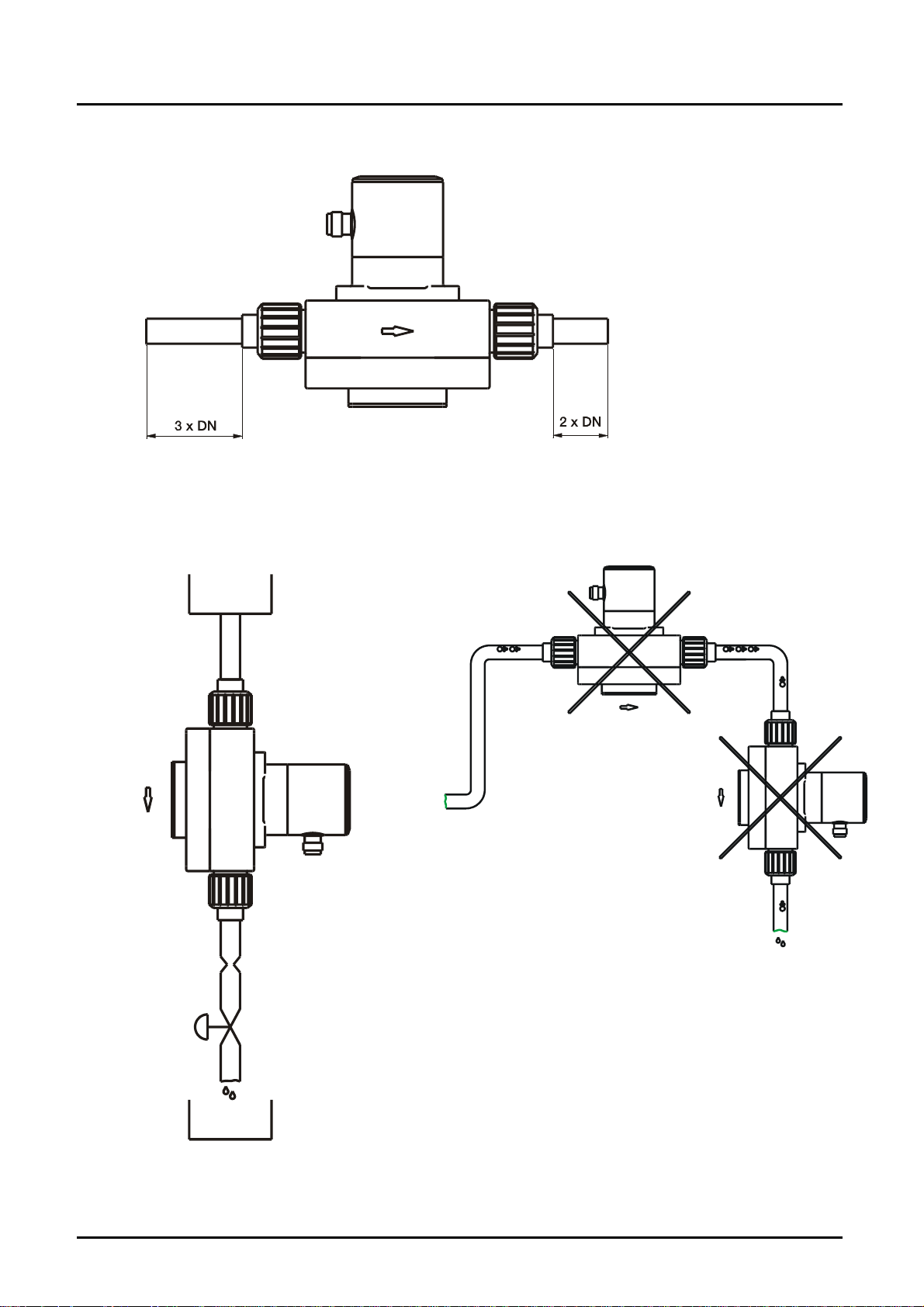
6.2 Installation
Remove all packing materials and transport retainers and ensure that no such
materials remain in the device.
It can be installed in vertical, horizontal or rising pipes. Flow in direction of the
arrow.
Avoid pressure and tensile load.
Mounting the inlet and outlet pipe in a distance of 50 mm from the connections.
Attention! The sensor housing made of PPS and PVDF is not
allowed to be subjected to a torsional stress during installation.
The connecting of the respective connection thread with the
pipeline should be adapted to the material used, over tightening
the connection will damage the sensor housing, a loose
tightening may result in loosening the connection.
Avoid valves or large reduction on the inlet section (this increases the
inaccuracy of measurements).
Check the leak tightness of the connections.
page 6 MIK K07/0614
Page 7
MIK
in- and outlet
mounting top down avoid this mounting position
MIK K07/0614 page 7
Page 8
MIK
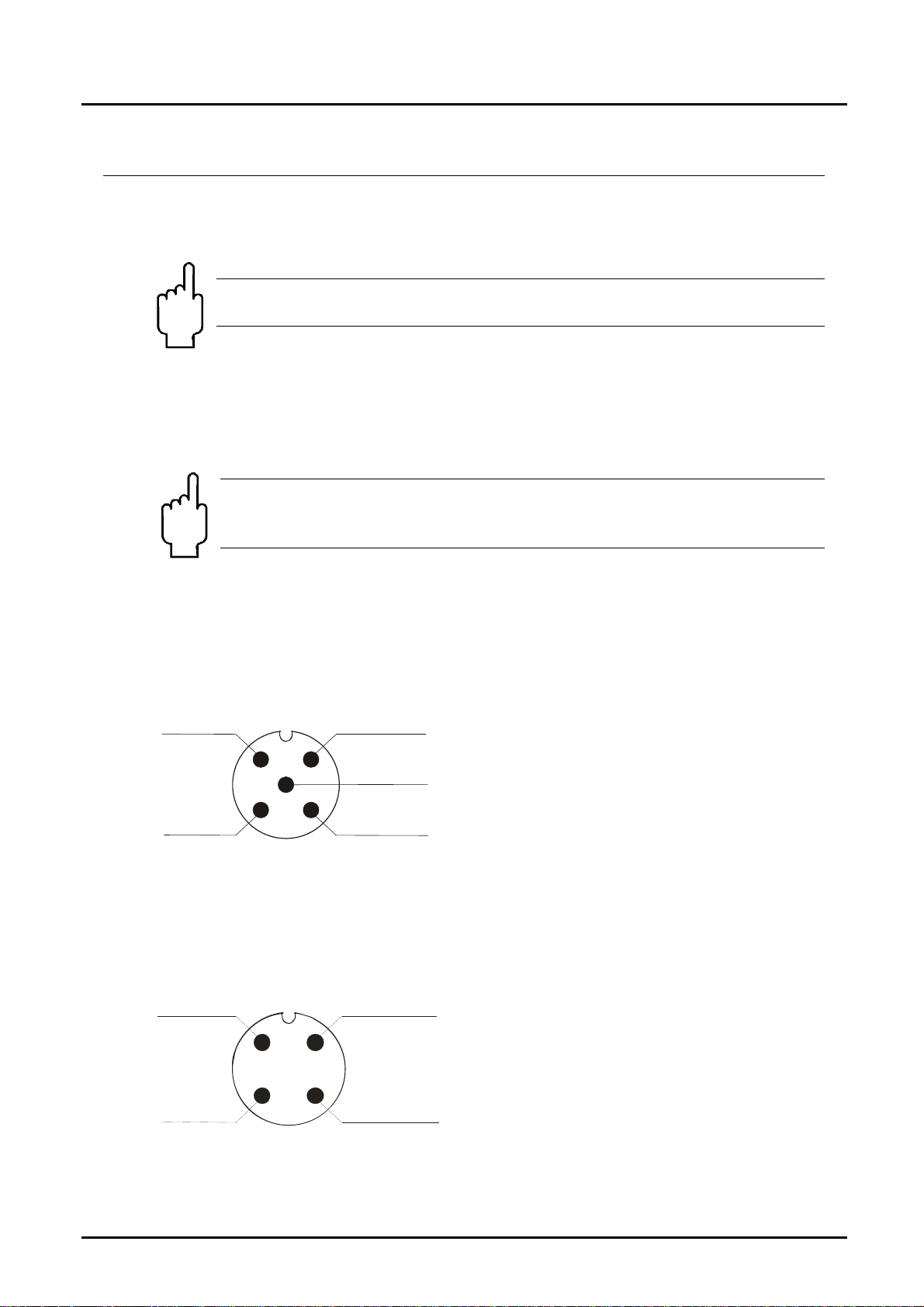
7. Electrical Connection
7.1 General
Attention! Make sure that the voltage values of your system
correspond with the voltage values of the measuring unit.
Make sure that the supply wires are de-energised.
Connect the supply voltage and the output signal to the plug PIN’s as stated
below.
We recommend the use of wires with cross sectional area of min. 0,25 mm².
Attention! The measuring electrodes are galvanically connected
with the reference potential of the supply voltage and the signal
output.
7.2 MIK-...S300
Output
N/O
2
5
GND
3
7.3 MIK-...S30D
Output
N/C
1
Common
4
12
+Vs
Output
Output
N/C
+Vs
GND
3
page 8 MIK K07/0614
4
Output
N/O
Page 9

MIK
1
7.4 MIK-...F300; MIK-...L3x3
Connection example MIK-...L3x3
+Vs
n.c.
2
GND
3
7.5 MIK-...L443
1
4
+Vs
GND
+Vs
Signal
Out
2
n.c.
GND
Signal
Out
GND
3
+Vs
GND
1
4
+Vs
Signal
Out
7.6 MIK-...C30..
Switch
Out 2
GND
MIK K07/0614 page 9
2
5
3
4
1
+Vs
GND
Switch
Out 1
7.7 MIK-...C34..
0(4)-20 mA
2
5
GND
3
1
+Vs
GND
Switch out
4
Page 10

MIK
7.8 MIK-...Ex4R, MIK-...Gx4R
Cable connection
Wire number
MIK-...E14R
Counter electronics
1 +24 VDC +24 VDC
2 GND GND
3 4-20 mA 4-20 mA
4 GND GND
5 n. c. Control 1*
6 Reset part quantity Control 2*
7 Relay S1 Relay S1
8 Relay S1 Relay S1
9 Relay S2 Relay S2
10 Relay S2 Relay S2
*Control 1<->GND: Start-dosing
Control 2<->GND: Stop-dosing
Control 1 <-> Control 2 <-> GND: Reset-dosing
Plug connection
-E34 R
+ Vs
0 (4) - 20 mA
MIK-...G14R
Dosing electronics
S 2
Reset TM
d.c. *)
1
5
34
30 V / 2 A
AC/DC
1
8
6
5
Output
GND
3
4
*) Do not connect !
page 10 MIK K07/0614
Page 11

MIK
8. Operation
The units are preset and after electrical connection ready for operation.
8.1 Switch point setting MIK-...S300, MIK-…S30D
Switch setting Switch point
0 Switch function deactivated
1 10 % of f.s.
2 20 % of f.s.
3 30 % of f.s.
4 40 % of f.s.
5 50 % of f.s.
6 60 % of f.s.
7 70 % of f.s.
8 80 % of f.s.
9 90 % of f.s.
Flow above switch point: DUO-LED green
Flow below switch point: DUO-LED red
8.2 Counter electronics MIK-…Ex4R
Operating please see Operating Instructions ZED-Z
8.3 Dosing electronics MIK-…Gx4R
Operating please see Operating Instructions ZED-D
MIK K07/0614 page 11
Page 12

MIK
9. Adjustments – Compact Electronics MIK-...C3..
Connect the compact electronics according to previous connection diagram and
supply with the indicated power supply.
After power on, the measuring range (end current) will be shown for 3
seconds.
9.1 Button function
In the standard mode (measuring mode)
: Press 3 sec. Setup mode
: Switch point/Window point
In the set-up mode
: Next Step
Any time
3 sec
: Change Value
or do not press
a button for 20 sec
Standard mode
9.2 Settings
The following values can be changed in the compact electronic:
Scale range Factory setting
Switch point (SPo, SP1, SP2)
Hysteresis (HYS)
Window point (duo point) (duo)
Contact-type (Con, Co1, Co2) (no),(nc) or frequency (Fr)** no
Start current (S-C)*
End current (E-C)*
Start current selection (SCS)
Change Code (CCo)
* Start- and end value of flow relating to 0/4-20 mA
** not calibrated, frequency at f.s. approx. 500 -600Hz
0...999 0,00
-199...0 -0,00
Switch point ...999 --- (inactive)
000...999 000
000...999 FS
0-- (0 mA), 4-- (4 mA) 4 mA
000...999 000
page 12 MIK K07/0614
Page 13

MIK
9.3 Value setting
From the main menu item (for example: switch point, "SPo"), press the ""
button to set the value. The flow chart below illustrates the universal routine for
changing individual parameters.
[From the main menu item]
1. Adjust position
2. Adjust position
3. Adjust position
Adjust decimal point
Save selected value
or
save
[To the next main menu item]
enter new value.
MIK K07/0614 page 13
Page 14
MIK
g
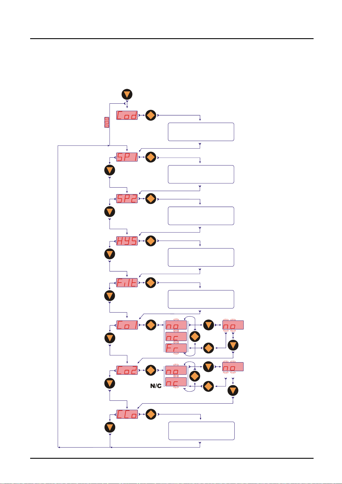
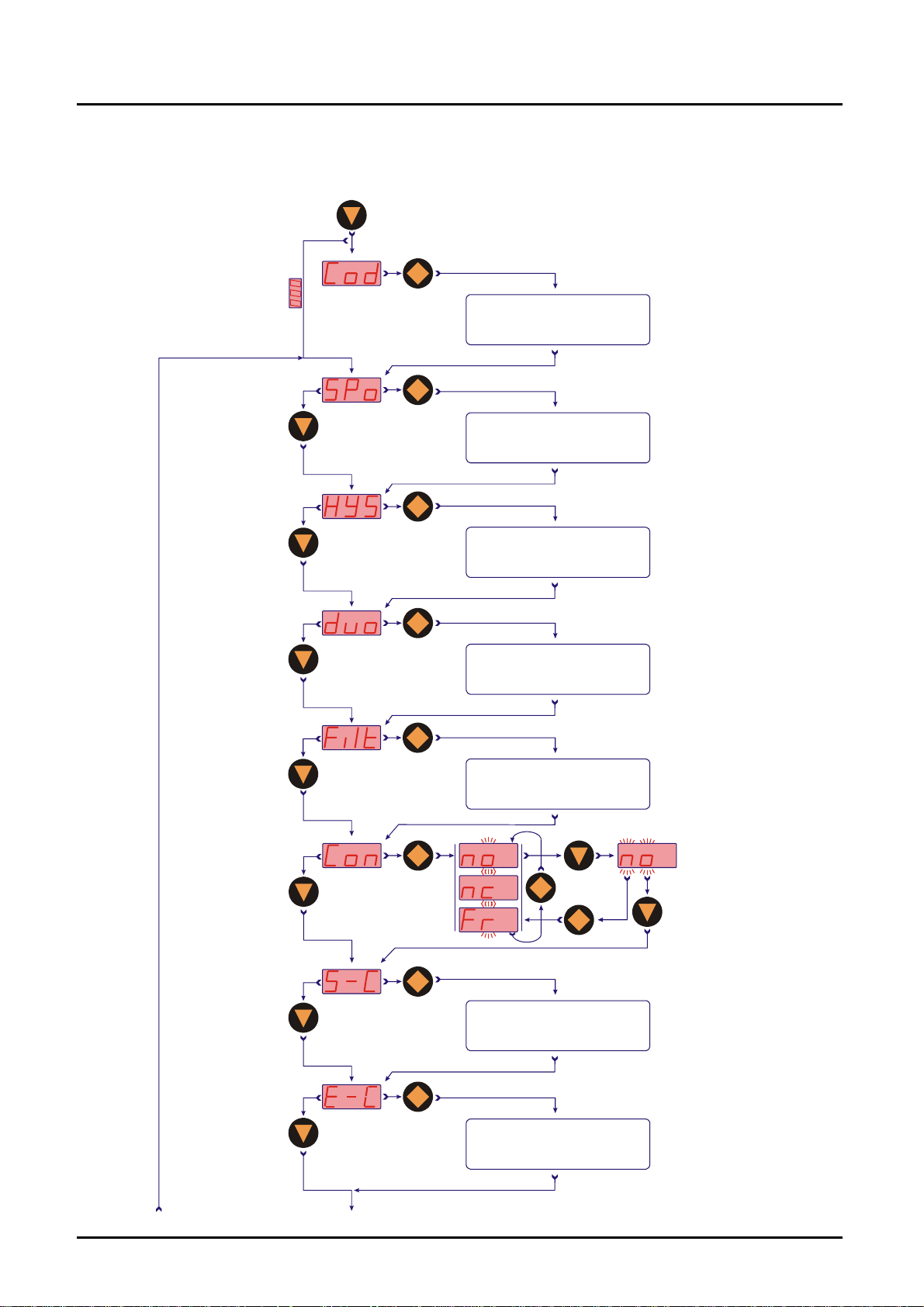
9.4 Set-up mode
Compact electronics MIK-...C30..
3 sec
Code entering
Value se tting
Code=
Swichting
point 1
Value setting
Switching
point 2
Hysteresis
Filter
Contact 1
function
Contact 2
function
7 Levels
N/O
N/C
Frequency
N/O
Value setting
Value setting
Value setting
Storin
Storing
Changing code
Value setting
page 14 MIK K07/0614
Page 15
MIK
g
Compact electronics MIK-...C34..
3 sec
Code entering
Value setting
Code=
Switching point
Value setting
Hysteresis
Windowpoint
Filter
Contact function
Start current
7 levels
N/O
N/C
Frequency
7sec
Value setting
Value setting
Value setting
Storin
Value setting
End current
7sec
Value setting
MIK K07/0614 page 15
Page 16

MIK
Start
selection
7sec
Changing code
0-20
mA
Save
4-20
mA
Value setting
9.5 Main menu items
9.5.1 Switching point
The switching point is entered in the menu item "Spo, SP1, SP2". A setting value
between 000 and 999 can be selected. This value can also include a decimal
point. The decimal point can be set at two points (e.g. 10.0 or 1.00). If the display
value exceeds the set switch point, the electronic is activated and is signalised by
a lightning LED.
If the hysteresis is equal to zero and the window point is de-activated, the
electronic switches back whenever the indicated value falls below the switching
point.
9.5.2 Hysteresis
After the setting of the switching point, the hysteresis can be entered as a
negative value in the "HYS" menu. The standard hysteresis value is zero. In
operation condition this can lead to ambiguous switching behaviour, if the reading
fluctuates around the switching point or window point. In this case, increasing the
hysteresis can put things right. The hysteresis relates to the switching point and
the window point (switching point minus hysteresis; window point plus
hysteresis).
Example: Switch point 100 L/min; Hysteresis: -2.5 L/min
The electronics switches when 100 L/min is exceeded and switches back when
the reading under-runs below 97.5 L/min.
page 16 MIK K07/0614
Page 17

MIK
9.5.3 Window point (duo-point)
As well as the switching point, it is also to define a "duo" (duo-point), the window
point. This must be higher than the switching point. By using the window point
and the switching point it is possible to monitor the measurement value in a
certain range. The switching point limits the measurement range to smaller
values and the window point to larger values.
If the window point (duo-point) is less than or equal to the switching
point, an error report (Er4) will be indicated on the display and its
value is deleted and its function is invalid (in the case that the
window point and switching point out of adjustment).
The value is set in the same way as the switch point.
The window point is needed for process, in which monitoring of a certain
measurement range is necessary.
Example: Switching point: 100 L/min; window point: 150 L/min;
hysteresis: -1 L/min
The electronic switches when 100 L/min is exceeded. If the measured value
remains between 99 L/min (100-1) and 151 L/min (150+1), the contact will also
remain in active switching condition (LED on). If it exceeds 151 L/min or is below
99 L/min the electronic switches back.
Switching behaviour
The following diagram clarifies the switching behaviour of the electronics. The
contact closes (contact type: no) when exceeding below the switching point or
when it under-runs the window point. It only opens again if the window point plus
hysteresis is exceeded or if it drops below the switching point minus hysteresis.
LED indicates the switching condition of the switching point.
An
9.5.4 Filter
The filter function "Filt" forms a running average from the measured values. The
following values can be set (see section 9.2 Settings):
1 / 2 / 4 / 8 / 16 / 32 / 64
They correspond to the number of samples used in the running average. The
filter value determines the dynamic behaviour of the display value. The larger the
adjusted value, the slower the display response. With a filter value of "1" the filter
is switched off, i.e. the display value is equal to the unfiltered measured value.
The integrated step function detector reacts to a change of value corresponding
to approx. 6.25% of the full scale value. As soon as a step function signal is
detected, the instantaneous measured value is directly indicated in the display.
MIK K07/0614 page 17
Page 18

MIK
Display
L/min
Switchpoint
Hysteresis
Display
L/min
Hysteresis
Window point
LED on
Time / t
LED on
LED on
Switchpoint
Hysteresis
Time / t
9.5.5 Contact type
The function of the transistor switching output is set in menu item "Con, Co1 or
". The switching function switches from
Co2
no - N/O contact to
nc - N/C to
Fr – frequency (only Con and Co1)
and back.
N/O contact: contact closes when switch point is exceeded
N/C contact: contact opens when switch point is exceeded
Frequency: frequency output is proportional to flow value
9.5.6 Current output
The current output is selected in menu items
"S-C" Start current indicated value < > 0(4) mA
"E-C" End current indicated value < > 20 mA
"SCS" Start current selection (0-20 mA or 4-20 mA).
The indicated value at which 0(4) mA flow is entered in menu item start current.
The indicated value at which 20 mA flow is entered in menu item end current.
page 18 MIK K07/0614
Page 19

MIK
9.5.7 Change code
The change code option "CCo" secures the unit against unauthorised tampering.
If the code is different from 000, the user must input the code immediately after
entering the adjustment mode.
10. Maintenance
The measurement device requires no maintenance if the measurement medium
does not cause deposits. In order to avoid problems, we recommend the
installation of a filter, such as the magnetic filter, model MFR.
If it is necessary to clean the sensor, the sensor can be rinsed with a suitable
liquid. Fibre parts or large particles can be carefully removed with a cleaning cloth
or similar.
Work on the electronics can only be performed by the factory, or the warranty is
otherwise voided.
MIK K07/0614 page 19
Page 20

MIK
11. T echnical Information
Range: see table
Accuracy: ±2.0 % of f.s.
Repeat accuracy: ±1 % of f.s.
(f.s. = full scale)
Measurement process: magnetic inductive
Electrical conductivity: min. 30 µS/cm
Mounting position: in all directions,
flow in direction of the arrow
Inlet / outlet: 3 x DN / 2 x DN
Media temperature: -20…+80 °C (max. +60 °C with PVC-
Ambient temperature: -10…+60 °C
Max. pressure: 10 bar
Max. pressure loss: max. 0.25 bar at f.s.
Max. medium viscosity: 20 cSt ≤ G1”
Max. medium viscosity: 70 cSt ≥ G1½”
Wetted parts
Sensor housing: PPS or PVDF, fibreglass-reinforced
Connection set: PVC-glue connection or hose connection,
Electrodes: st. st. 1.4404 or Hastelloy C4
Seal: NBR, FPM or FFKM
Response time t90: approx. 1 s
Protection: IP 65
Connection/Ranges
Inside
Connection
G ½ male 5 mm
G ¾ male 10 mm
G 1 male 15 mm
G 1½ male 20 mm
G 2 male 32 mm
G 2¾ male 54 mm
diameter
[DN]
connection set)
weld-on ends st. st. 1.4404
Flow velocity
at f.s.
approx. 0,45 m/s 10...500 mL/min
approx. 0,9 m/s 0,05...1,0 L/min
approx. 2,7 m/s 0,16...3,2 L/min
approx. 2,2 m/s 0,5...10,0 L/min
approx. 3,5 m/s 0,8...16,0 L/min
approx. 3,0 m/s 1,6...32,0 L/min
approx. 4,7 m/s 2,5...50,0 L/min
approx. 3,3 m/s 3,2...63 L/min
approx. 5,3 m/s 5,0...100 L/min
approx. 3,3 m/s 8...160 L/min
approx. 6,6 m/s 16...320 L/min
approx. 3,6 m/s 25...500 L/min
approx. 5,1 m/s 35...700 L/min
Measuring range
page 20 MIK K07/0614
Page 21

MIK
Weight Sensor Weight Electronics
Model PPS PVDF Model Weight
MIK-...08/10/15 (½“) approx. 180 g approx. 210 g
MIK-...20/25 (¾“) approx. 190 g approx. 225 g
MIK-...30/35 (1“) approx. 270 g approx. 325 g
MIK-...50/55 (1½“) approx. 410 g approx. 500 g MIK-...C3xx approx. 300 g
MIK-...60/65 (2“) approx. 560 g approx. 610 g
MIK-...80/85 (2¾“) approx. 1200 g approx. 1370 g
Total weight = weight sensor + weight electronics
MIK-...F300, MIK-…F390
Impulse output: PNP, Open Collector, max. 200 mA
500 Hz at f.s. (…F300)
50…1000 HZ at f.s. (…F390)
factory set as per customer request
Power supply: 24 V
± 20 %
DC
Power consumption: 60 mA
Electrical connection: plug M12x1
Measuring range overflow: F
approx. 2 kHz up to 105% of f.s.
out
MIK-...S300, MIK-…S30D
Display: duo-LED for switch status
Switching output (..S300): relay SPDT, max. 1 A/30 VDC
Switching output (..S30D): active 24 VDC, , N/C and N/O
Switch point: 10...90 % f.s. in 10 %-steps
that can be configured by the
customer using a rotary encoder switch
Power supply: 24 VDC ± 20 %
Power consumption: 80 mA
Electrical connection: plug M12x1, 5-pin
Measuring range overflow: flash of the DUO-LED (red/green)
up to 105 % of f.s.
MIK-...L303; MIK-...L343
Output: 0(4)-20 mA, 3-wire
Max. load: 500 Ω
Power supply: 24 V
± 20 %
DC
Power consumption: 80 mA
Electrical connection: plug M12x1
Measuring range overflow: I
approx. 20,5 mA up to 103 % of f.s.
out
MIK-...L443 (usage with AUF-3000)
Output: 4-20 mA, 3-wire
Max. load: 500 Ω
Power supply: 24 V
± 20 %
DC
Power consumption: 80 mA
Electrical connection: plug DIN 43650
Measuring range overflow: I
approx. 20,5 mA up to 103 % of f.s.
out
MIK-...F3x0
MIK-...S30x
MIK-...Lxx3
MIK-...Exxx
MIK-...Gxxx
approx. 80 g
approx. 250 g
MIK K07/0614 page 21
Page 22

MIK
MIK-...C3xx (Compact electronics)
Display: 3-digit LED
Analogue output: (0)4...20 mA adjustable
(only MIK-…C34x),
Max. load: 500 Ω
Switching output: 1(2) semiconductor PNP or NPN,
set at factory, max. 300 mA
Contact function: N/C, N/O, frequency, programmable
(frequency output not calibrated, frequency
at f.s. approx. 750 - 850 Hz)
Setting: with 2 buttons
Power supply: 24 V
± 20 %, 3-wire
DC
Power consumption: approx. 120 mA
Electrical connection: plug M12x1
MIK-...Exxx (Counter electronics)
Display: LCD, 2x8 digit, illuminated
total, part and flow quantities,
units selectable
Quantity meter: 8-digit
Analogue output: (0)4...20 mA adjustable
Load: max. 500 Ω
Switching output: 2 relays, max. 30 V
/2 A/60 VA
AC/DC
Settings: via 4 buttons
Functions: reset, MIN/MAX memory,
flow monitor, monitoring for part
and total quantity, language
Power supply: 24 VDC ±20 %, 3-wire
Power consumption: approx. 150 mA
Electrical connection: cable connection or M12 plug
more technical details see data sheet ZED in the brochure Z2
MIK-...Gxxx (Dosing electronics)
Display: LCD, 2x8 digit, illuminated,
dosing, total and flow quantity,
units selectable
Quantity meter: 8-digit
Dosage: 5-digit
Analogue output: (0)4...20 mA adjustable
Load: max. 500 Ω
Switching output: 2 relays, max. 30 V
/2 A/60 VA
AC/DC
Settings: via 4 buttons
Functions: dosing (relay S2), start, stop, reset, fine
dosing, correction amount, flow switch,
total quantity, language
Power supply: 24 VDC ±20 %, 3-wire
Power consumption: approx. 150 mA
Electrical connection: cable connection or M12 plug
more technical details see data sheet ZED in the brochure Z2
page 22 MIK K07/0614
Page 23

MIK
12. Order Codes
Order details (Example: MIK-5NA 10 A F300)
Model Range Connection set Electronics
..08..= 10…500 mL/min,
MIK-5NA...= PPS-housing,
NBR-seal,
st. st.- electrode
MIK-5VA...= PPS-housing,
FPM-seal,
st. st.-electrode
MIK-6FC...= PVDF-housing,
FFKM-seal,
HastelloyElectrode
MIK-6FT...= PVDF-housing,
FFKM-seal,
TantalumElectrode
G ½
..10..= 0.05…1.0 L/min,
G ½
..15..= 0.16…3.2 L/min,
G ½
..20..= 0.5…10.0 L/min,
G ¾
..25..= 0.8…16.0 L/min,
G ¾
..30..= 1.6…32.0 L/min,
G 1
..35..= 2.5…50.0 L/min,
G 1
..50.. = 3.2...63 L/min,
G 1½
..55.. = 5.0...100 L/min,
G 1½
..60.. = 8...160 L/min,
G 2
..65.. = 16...320 L/min,
G 2
..80.. = 25...500 L/min,
G 2¾
..85.. = 40...800 L/min,
G 2¾
1)
= without
..A..
..P..= PVC-hose connection
..E..= st. st. weld-on ends
1)
..A..
= without
..K..= PVC-glue connection
..P..= PVC-hose connection
..E..= st. st. weld-on ends
1)
= without
..A..
..K..= PVC-glue connection
..E..= st. st. weld-on ends
frequency output
..F300 =M12-plug, 500 Hz
..F390 =M12-plug,
50...1000 Hz
switching output
..S300 =relay, M12-plug
..S30D =active 24 VDC,
M12-plug
analogue output
..L303 =M12-plug, 0-20 mA
..L343 =M12-plug, 4-20 mA
..L443 =DIN-plug, 4-20 mA
compact electronics
..C30R =2xOpen Coll. PNP
..C30M=2xOpen Coll. NPN
..C34P =0(4)-20 mA,
1xOpen Coll. PNP
..C34N =0(4)-20 mA,
1xOpen Coll. NPN
counter electronics
..E14R =LCD, 0(4)-20 mA,
2xrelay, 1 m cable
..E34R =LCD, 0(4)-20 mA,
2xrelay, M12-plug
dosing electronics
..G14R =LCD, 0(4)-20 mA,
2xrelay, 1 m cable
..G34R =LCD, 0(4)-20 mA,
2xrelay, M12-plug
2)
1) incl. frontal gaskets (2 pc. O-rings)
2) please specify frequency at full scale in clear text while oderering
MIK K07/0614 page 23
Page 24

MIK
13. Dimensions
Model G L1 L2 L3 L4 L5 L6 H1 H2
MIK-xxx08A/10A/15A G ½ 118 90 14 46 58 36 43 28
MIK-xxx20A/25A G ¾ 112 90 16 46 58 36 43 28
MIK-xxx30A/35A G 1 126 90 18 46 58 36 49,5 29,5
MIK-xxx50A/55A G 1½ 134 90 22 68 80 36 65,6 31,5
MIK-xxx60A/65A G 2 138 90 24 68 80 36 72 36
MIK-xxx80A/85A G 2¾ 202 150 26 96 110 75 104 52
MIK-...F3x0; MIK-...S30x; MIK-...L3x3
MIK-...L443
page 24 MIK K07/0614
Page 25

MIK
MIK-...C3xx
MIK-...Ex4R, MIK-...Gx4R
MIK K07/0614 page 25
Page 26

MIK
L1
G
Dimensions Connection set PVC-glue connection
G Ø D1 Ø D2 Ø D3 L1 L2
G 1/2 not available
G 3/4 35 16 10,5 21 14
G 1 43 20 15 23 16
G 1 1/2 60 32 26 27 22
G 2 74 40 33 30 26
G 2 3/4 103 63 54 38 38
Dimensions Connection set PVC-hose connection
G Ø D1 Ø D2 L
G 1/2 14 12 56
G 3/4 18 16 60
G 1 22 20 67
G 1 1/2 not available
G 2 not available
G 2 3/4 not available
Dimensions Connection set st. st. weld-on-ends
G SW L Ø D1 Ø D2
G 1/2 24 45 10,2 5
G 3/4 32 45 13,5 10
G 1 41 45 19 15
G 1 1/2 55 60 25 20
G 2 70 60 38 32
G 2 3/4 90 60 60,3 54
G
Ø D1
L1
3
G
L2
Ø D3
Ø D2
D1
D2
ø
ø
L
øD2
øD1
38
page 26 MIK K07/0614
Page 27

MIK
14. Declaration of Conformance
We, KOBOLD Messring GmbH, Hofheim-Ts, Germany, declare under our sole
responsibility that the product:
Compact Magnetic-Inductive Flow Meter Model: MIK-…
to which this declaration relates is in conformity with the standards noted below:
EN 61320-1 2013-07
Electrical equipment for control and instrumentation technology and laboratory
use – EMC-requirements
DIN EN 61010-1 2011-07
Safety requirements for electrical measuring-, control- and laboratory instruments
Also the following EC guidelines are fulfilled:
2004/108/EC EMC Directive
Hofheim, 03.06.2014
H. Peters M. Wenzel
General Manager Proxy Holder
MIK K07/0614 page 27
 Loading...