

Page 1
03/08- 2016
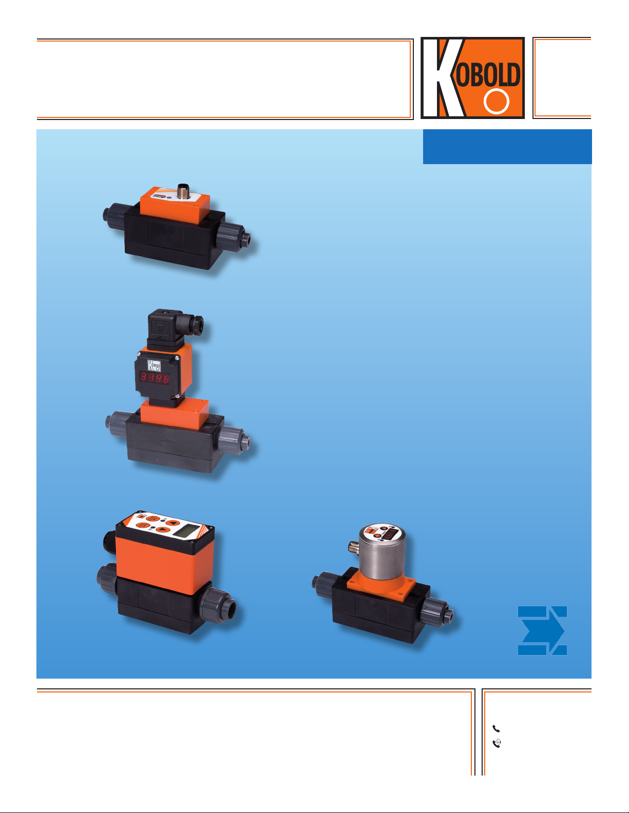
MIK
Compact Magneto-Inductive
Flowmeter
●● Flow Ranges: 0.18...7.8 GPH to 9...180 GPM
●● Accuracy: ±2 % of Full Scale
●● p
: 145 psi; t
max
●● Connection: G½...G 2¾ Male with
Optional NPT, Socket, and Hose Connections
●● Materials: PPS Body with Stainless Steel
Electrodes; PVDF Body with Hastelloy® or
Tantalum Electrodes
: 176 °F
max
measuring
•
monitoring
•
analyzing
●● Electronic Packages: Frequency or Current
Outputs, Adjustable Switches, and Integral
Totalizers or Batch Controllers
●● Highlights:
· No Moving Parts in the Flow Body
· Low Pressure Loss
· Universal Mounting
· High Quality at a Low Price
KOBOLD companies worldwide:
ARGENTINA, AUSTRALIA, AUSTRIA, BELGIUM, BULGARIA, CANADA, CHILE, CHINA, COLOMBIA, CZECH
REPUBLIC, EGYPT, FRANCE, GERMANY, HUNGARY, INDIA, INDONESIA, ITALY, MALAYSIA, MEXICO,
NETHERLANDS, PERU, POLAND, REPUBLIC OF KOREA, ROMANIA, SINGAPORE, SPAIN, SWITZERLAND,
TAIWAN, THAILAND, TUNISIA, TURKEY, UNITED KINGDOM, USA, VIETNAM
KOBOLD Instruments, Inc.
1801 Parkway View Drive
Pittsburgh, PA 15205
Main Ofce:
1.800.998.1020
1.412.788.4890
info@koboldusa.com
www.koboldusa.com
Page 2
Compact Magneto-Inductive Flowmeter Model MIK
Description
The KOBOLD MIK fl ow meter is used for measuring and
monitoring small to medium-sized fl ows of conductive liquids in
pipes. The sensor operates according to the electromagnetic
measurement principle. According to Faraday’s Law of magnetic
induction, a voltage is induced in a conductor moving through
a magnetic fi eld. The electrically conductive media acts as the
conductor. The voltage induced in the media is proportional
to the fl ow velocity and is therefore a value for the volumetric
fl ow. The media must have a minimum conductivity of 30 μS
/cm (200 μS /cm for U0 & U1 ranges) for proper operation.
The induced voltage is picked up by two sensing electrodes
which are in contact with the media and sent to the measuring
amplifi er. The fl ow rate will be calculated based on the cross
sectional area of the pipe.
The measurement is not dependent on the process liquid and its
material properties such as density, viscosity, and temperature.
The device may be equipped with a switch, frequency, or analog
output. Moreover, there is a compact electronic option, which
contains a switch and an analog output. The sensor series is
completed by an optional batching or totalizer electronic option.
The totalizer electronic option displays the current fl ow rate on
the fi rst line of the display and shows the partial or grand total
volume on the second. A batching electronic controls simple
fi lling duties and also measures the fl ow rate, grand total
volume, and fi lling volume. The analog output and two relay
outputs can be utilized for the further processing.
Media
Conductive Liquids
Acids and Caustic Solutions
Drinking, Cooling, and Waste Water
Ground Water, Raw Water
Aggressive or Salty Solutions
Unsuitable for Oils & Other Low or Non-Conductive Medias
Areas of Application
Flow Monitoring, Flow Measuring, Batching and
Totalizing for:
Machine Building
Chemical Industry
Paper Industry
Automobile Industry
Cement Industry
Laboratories
Technical Data
Range: See Table
Accuracy: ±2.0 % of f. s.
Repeat Accuracy: ±1.0 % of f. s.
(f. s. = full scale)
Measurement Process: Electromagnetic
Electrical Conductivity: Min. 30 μS /cm (MIK-..U0.. & MIK-..
U1.., Min. 200 μS /cm)
Mounting Position: Universal,
Flow in Direction of the Arrow
Inlet/Outlet Straight Run: 3 x PD / 2 x PD (Pipe Diameters)
Media Temperature: -4 ... 176 °F (max. 140 °F
with PVC-connection Set)
Ambient Temperature: 14 ... 140 °F
Max. Pressure: 145 psi
Max. Pressure Loss: Max. 3.7 psi at f.s.
Max. Media Viscosity: Max. 20 cSt for ranges: U0...U8
Max. 70 cSt for ranges: UA...UH
Wetted Parts
Sensor Housing: PPS or PVDF, Fiberglass-reinforced
Native Connection: G 1/2 to G 2-3/4
Optional Connection Set: NPT, PVC-glue Connections, Hose
Barb, or Butt Weld Connections
316L Stainless Steel
Electrodes: 316L Stainless Steel, Hastelloy C4,
or Tantalum
Seal: NBR, FKM, or FFKM
Response Time t
: ca. 1 s
90
Protection: IP 65
Connection/Ranges
Native
Connection
G ½ male 5 mm
G ¾ male 10 mm
G 1 male 15 mm
G 1 ½ male 20 mm
G 2 male 32 mm
G 2 ¾ male 54 mm
Inside
Diameter
Flow Velocity
at f.s.
approx. 0.45 m/s 0.18... 7.8 gph
approx. 0.9 m/s 0.78... 15.6 gph
approx. 2.7 m/s 2.4... 48.0 gph
approx. 2.2 m/s 0.13 ... 2.6 gpm
approx. 3.5 m/s 0.2 ... 4.0 gpm
approx. 3.0 m/s 0.4 ... 8.0 gpm
approx. 4.7 m/s 0.65 ... 13 gpm
approx. 3.3 m/s 0.8... 16 gpm
approx. 5.3 m/s 1.3 ... 26 gpm
approx. 3.3 m/s 2.0 ... 40 gpm
approx. 5.9 m/s 4.0 ... 75 gpm
approx. 3.6 m/s 6.5 ... 130 gpm
approx. 5.1 m/s 9.0 ... 180 gpm
Range
2
www.koboldusa.com
No responsibility taken for errors;
subject to change without prior notice.
Page 3

Compact Magneto-Inductive Flowmeter Model MIK
MIK-...F300, MIK-...F390
Pulse Output: PNP, Open Collector, max. 200 mA
500 Hz at f. s. (...F300)
50...1000 Hz at f. s. (...F390)
Factory Set as per Customer Request
Power Supply: 24 VDC ±20 %
Power Consumption: 60 mA
Electrical Connection: Plug M 12 x 1
MIK-...S300, MIK-...S30D
Display: Duo-LED for Switch Status
Switching Output: Relay SPDT, Max. 1A/30V
or Active 24 VDC, N/C / N/O
DC
Switch Point: 10 ...100% of f. s. in 10%-Steps
User Configured via Rotary Switch
Power Supply: 24 VDC ±20 %
Power Consumption: 80 mA
Electrical Connection: Plug M 12 x 1, 5-pin
MIK-...L343
Output: 4-20 mA, 3-wire
Max. Load: 500 Ω
Power Supply: 24 VDC ±20%
Power Consumption: 80 mA
Electrical Connection: Plug M 12 x 1
MIK-...L443 (Optional Use with AUF-3000)
Output: 4-20 mA, 3-wire
Max. Load: 500 Ω
Power Supply: 24 VDC ±20%
Power Consumption: 80 mA
Electrical Connection: Plug DIN 43650
MIK-...Ex4R (Totalizing Electronic)
Display: LCD, 2 x 8 Digit, Illuminated
Rate, Total, and Grand Total
Unit Selectable
Quantity Meter: 8-digit
Analog Output: 4-20 mA Adjustable
Load: Max. 500 Ω
Switching Output: 2 Relays, Max. 30 V / 2 A
Settings: Via 4 buttons
Functions: Reset, MIN / MAX Memory,
Flow Switch, Monitoring for Total
and Grand Total, Language
Power Supply: 24 VDC ±20 %, 3-wire
Power Consumption: Approx. 150 mA
Electrical Connections: Cable Connection or M12 Plug
MIK-...Gx4R (Batching Electronic)
Display: LCD, 2 x 8 Digit, Illuminated
Batching, Total, and Grand Total
Unit Selectable
Quantity Meter: 8-digit
Batch: 5-digit
Analog Output: 4-20 mA Adjustable
Load: Max. 500 Ω
Switching Output: 2 relays, Max. 30 V / 2 A
Settings: Via 4 Buttons
Functions: Batching (Relay S2), Start, Stop,
Reset, Fine Batching,
Correction Amount, Flow Switch,
Total Quantity, Language
Power Supply: 24 VDC ±20 %, 3-wire
Power Consumption: Approx. 150 mA
Electrical Connection: Cable Connection or M12 Plug
MIK-...C3xx (Compact Electronics)
Display: 3-digit LED
Analog Output: 4...20 mA Adjustable
(only MIK-...C34P)
Max. Load: 500 Ω
Switching Output: 1(2) Semiconductor PNP or NPN,
Set at Factory
Contact Function: N/C / N/O-Frequency
Programmable
Settings: Via 2 Buttons
Power Supply: 24 VDC ±20 %, 3-wire
Power Consumption: 120 mA
Electrical Connection: Plug M 12 x 1
No responsibility taken for errors;
subject to change without prior notice.
www.koboldusa.com
3
Page 4

Compact Magneto-Inductive Flowmeter Model MIK
1
2
Switch out 2
+Vs
Electrical Connections
MIK-...S300 MIK-...S30D
Output
2
1
+Vs
N/O
Output
4
Common
Output
N/C
5
GND
3
MIK-...L343, MIK-...F3x0 MIK-...L443
n.c.
GND
MIK-...C30x MIK-...C34x
34
GND
12
+Vs
Signal out
5
3
4
GND
Switch out 1
Output
N/C
GND
2
1
0(4)-20 mA
GND
2
3
3
GND
Signal
out
+V
1
4
S
12
5
34
+Vs
Output
N/O
+Vs
GND
Switch out 1
MIK-...E14R, MIK-...G14R Cable Connection Plug Connection
Wire Number
1 +24 V
2 GND GND
3 4-20 mA 4-20 mA
4 GND GND
5 n.c. Control 1*
6 Reset part quantity Control 2*
7 Relay S1 Relay S1
8 Relay S1 Relay S1
9 Relay S2 Relay S2
10 Relay S2 Relay S2
Control 1 <-> GND: Start-Batching
Control 2 <-> GND: Stop-Batching
Control 1 <-> Control 2: Reset-Batching
4
MIK-...E14R
Totalizing Electronics
MIK-...G14R
Batching Electronics
DC
+24 V
DC
www.koboldusa.com
+24 V
DC
Reset/Ctr 2*
d.c./Ctr 1*
S 2
1
4
30 V
7
6
AC/DC
1
U
8
U
0 (4) - 20 mA Out
2
5
3
/ 2 A
2
3
4
5
max. 500 Ω
GND
S 1
No responsibility taken for errors;
subject to change without prior notice.
Page 5

Compact Magneto-Inductive Flowmeter Model MIK
Order Details (Example: MIK-5NA U5 A F300)
Model
MIK-5NA.. = PPS-housing,
NBR-seal,
stainless steel electrode
MIK-5VA.. = PPS-housing,
FKM-seal,
stainless steel electrode
MIK-6FC.. = PVDF-housing,
FFKM-seal,
Hastelloy electrode
MIK-6FT.. = PVDF-housing,
FFKM-seal,
Tantalum electrode
Measuring Range, Native
Process Connection
..U0.. = 0.18…7.8 GPH, G ½
..U1.. = 0.78…15.6 GPH, G ½
..U2.. = 2.4…48.0 GPH, G ½
..U4.. = 0.13…2.6 GPM, G ¾
..U5.. = 0.2…4.0 GPM, G ¾
..U7.. = 0.4…8.0 GPM, G 1
..U8.. = 0.65…13 GPM, G 1
..UA.. = 0.8...16 GPM, G 1½
..UB.. = 1.3...26 GPM, G 1½
..UD.. = 2.0...40 GPM, G 2
..UE.. = 4.0...75 GPM, G 2
..UG.. = 6.5...130 GPM, G 2 ¾
..UH.. = 9.0...180 GPM, G 2 ¾
Optional Fitting Set Output/Electronics
..A.. = without
1)
..N.. = PVC, 1/4" NPT female
..P.. = PVC, 1/2" hose barb
..A.. = without
1)
..M.. = PVC, 3/8" PVC glue socket
..N.. = PVC, 3/8" NPT female
..P.. = PVC, 3/4" hose barb
..R.. = Polypropylene, 3/8" NPT female
..A.. = without
1)
..H.. = PVDF, 1/2" NPT female
..M.. = PVC, 1/2" glue socket
..N.. = PVC, 1/2" NPT female
..P.. = PVC, 1" hose barb
..R.. = Polypropylene, 1/2" NPT female
..V.. = PVDF, butt weld 20mm O.D. tube
..W.. = 316L SS, 1/2" NPT female
..X.. = Brass, 1/2" NPT female
..A.. = without
1)
..H.. = PVDF, 1" NPT female
..M.. = PVC, 1" glue socket
..N.. = PVC, 1" NPT female
..R.. = Polypropylene, 1" NPT female
..V.. = PVDF, butt weld 32mm O.D. tube
..A.. = without
1)
..H.. = PVDF, 1-1/4" NPT female
..M.. = PVC, 1-1/4" glue socket
..N.. = PVC, 1-1/4" NPT female
..R.. = Polypropylene, 1-1/4" NPT female
..A.. = without
1)
..H.. = PVDF, 2" NPT female
..M.. = PVC, 2" glue socket
..N.. = PVC, 2" NPT female
..R.. = Polypropylene, 2" NPT female
Frequency Output
..F300 = M12-plug, 500 Hz
..F390 = M12-plug,
50...1000 Hz
2)
Switching Output
..S300 = relay, M12-plug
..S30D = active 24 VDC,
M12-plug
Analog Output
..L343 = M12-plug, 4 - 20 mA
..L443 = DIN-plug, 4 - 20 mA
Compact Electronic
3)
..C30R = Open Coll. PNP (2x)
..C30M = Open Coll. NPN (2x)
..C34P = 4 - 20 mA,
Open Coll. PNP
..C34N = 4 - 20 mA,
Open Coll. NPN
Totalizing Electronic
..E14R = LCD, 4-20 mA,
relay (2x), 5' cable
..E34R = LCD, 4-20 mA,
relay (2x),
M12 plug (2x)
Batching Electronic
..G14R = LCD, 4-20 mA,
relay (2x), 5' cable
..G34R = LCD, 4-20 mA,
relay (2x),
M12 plug (2x)
Accessories: P/N 807.037 = 4-pin Micro-DC connector with 6-foot cable for output types F300, F390, L343, & S30D
P/N 807.007 = 5-pin Micro-DC connector with 6-foot cable for output types C3xx, S300, E34R, & G34R
P/N 807.087 = 8-pin Micro-DC connector with 6-foot cable for output types E34R & G34R
1)
incl. frontal gaskets (2 pc. O-rings)
2)
Please specify frequency at full scale in clear text while ordering
3)
Please clearly specify flow direction when ordering
Sensor Weight Electronics Weight
Model PPS PVDF
MIK-...U0/U1/U2 (½") approx. 0.40 lb approx. 0.43 lb
MIK-...U4/U5 (¾") approx. 0.42 lb approx. 0.50 lb
MIK-...U7/U8 (1") approx. 0.60 lb approx. 0.72 lb
MIK-...UA/UB (1 ½") approx. 0.90 lb approx. 1.10 lb
MIK-...UD/UE (2") approx. 1.24 lb approx. 1.35 lb
MIK-...UG/UH (2 ¾") approx. 2.65 lb approx. 3.02 lb
No responsibility taken for errors;
subject to change without prior notice.
Total Weight = Sensor Weight + Electronics Weight
www.koboldusa.com
Model Weight
MIK-...F3x0
MIK-...S30x
MIK-...Lxx3
MIK-...C3xx approx. 0.67 lb
MIK-...Exxx
MIK-...Gxxx
approx. 0.18 lb
approx. 0.56 lb
5
Page 6

Compact Magneto-Inductive Flowmeter Model MIK
L1
48 90
Dimensions
Model G L1 L2 L3 L4 L5 L6 H1 H2
MIK-xxxU0A
MIK-xxxU1A
G ½ 118 90 14 46 58 36 43 28
MIK-xxxU2A
MIK-xxxU4A
MIK-xxxU5A
MIK-xxxU7A
MIK-xxxU8A
MIK-xxxUAA
MIK-xxxUBA
MIK-xxxUDA
MIK-xxxUEA
MIK-xxxUGA
MIK-xxxUHA
G ¾ 122 90 16 46 58 36 43 28
G 1 126 90 18 46 58 36 49,5 29,5
G1 ½ 134 90 22 68 80 36 66 31,5
G 2 138 90 24 68 80 36 72 36
G 2 ¾ 202 150 26 96 110 75 104 52
MIK-...F3x0, MIK-...S30x, MIK-...L343 MIK-...L443
L1
L2
M12
L3 L2
26
L3
31
H1
H2
9
L4
L5
G
L6
55,5
45,5
H1
H2
9
L4
L5
MIK-...C3xx MIK-...Ex4R, MIK-...Gx4R
ø44,5
61
37,5
H1
H2
9
L4
L5
G
L3 L2
L1
M12
L6
ca. 61
H1
9
H2
L4
L5
G
L6
G
L6
L3
L2
L1
6
www.koboldusa.com
No responsibility taken for errors;
subject to change without prior notice.
Page 7

Compact Magneto-Inductive Flowmeter Model MIK
L
G
D1
D2
G
L
G
D
L1
L2
Dimensions Fitting Set ..H, M, N, R, W, X.. Connection
Reference table 7.1...table 7.5
fig. 7.1
Dimensions Fitting Set ..N.. PVC-NPT Connection
G L1 L2 D
G ½ Refer to figure 7.2 1/4" nom.
G ¾ 0.68" 0.52" 3/8" nom.
G 1 0.76" 0.68" 1/2" nom.
G 1 ½ 0.98" 0.87" 1" nom.
G 2 1.33" 0.98" 1-1/4" nom.
G 2 ¾ 1.61" 0.98" 2" nom.
table 7.1
Dimensions Fitting Set ..M.. PVC-IPS Glue Connection
G L1 L2 D
G ¾ 0.87" 0.79" 3/8" nom.
G 1 1.0" 0.89" 1/2" nom.
G 1 ½ 1.24" 1.14" 1" nom.
G 2 1.51" 1.39" 1-1/4" nom.
G 2 ¾ 1.61" 1.5" 2" nom.
table 7.2
Dimensions Fitting Set ..N.. PVC- 1/4" NPT Connection
Reference table 7.1 G ½ only
1.57“
1.10“
1.18“
G1/2
SW 1“
1/4“ NPT
fig. 7.2
Dimensions Fitting Set ..H.. PVDF-NPT Connection
G L1 L2 D
G 1 0.96" 0.79" 1/2" nom.
G 1 ½ 1.09" 0.83" 1" nom.
G 2 1.34" 0.91" 1-1/4" nom.
G 2 ¾ 1.65" 1.22" 2" nom.
table 7.3
Dimensions Fitting Set ..R.. PP-NPT Connection
G L1 L2 D
G ¾ 0.68" 0.55" 3/8" nom.
G 1 0.98" 0.79" 1/2" nom.
G 1 ½ 1.24" 0.94" 1" nom.
G 2 1.48" 1.18" 1-1/4" nom.
G 2 ¾ 1.68" 1.22" 2" nom.
table 7.4
Dimensions Fitting Set ..W, X.. SS/Brass-NPT Connection
G L1 L2 D
G 1 1.18" 0.63" 1/2" nom.
table 7.5
Dimensions Fitting Set ..V.. Butt Weld
G L D1 D2
G 1 2.09" 0.79" 0.62"
G 1 ½ 2.32" 1.26" 1.05"
No responsibility taken for errors;
subject to change without prior notice.
Dimensions Fitting Set ..P.. PVC-Hose Connection
D1
fig. 7.4
D2
fig. 7.3
G L D1 D2
table 7.6
www.koboldusa.com
G ½ 2.2" 0.55" 0.47"
G ¾ 2.36" 0.71" 0.63"
G 1 2.64" 0.87" 0.79"
table 7.7
7
 Loading...