

Page 1

KOBOLD MAS Series
Thermal Mass
Flowmeters
March 1997
r2_12-13
Part Number:
IM-82
(412) 788-2830 · (800) 998-1020 · Fax (412) 788-4890
KOBOLD Instruments Inc
1801 Parkway View Drive · Pittsburgh, PA 15205
Page 2
MAS Instruction Manual
The purpose of this instruction manual is to cover the following
Kobold Instruments Inc products:
Model MAS-1000 Flowmeter with Po
Model MAS-2000 Flowmeter with Polyamide body and no display.
Model MAS-3000 Flowmeter with stainless steel flow body and
display.
Model MAS-4000 Flowmeter with stainless steel flow body and no
display.
Model MAS-1100 Flowmeter with aluminum body and display.
Model MAS-2100 Flowmeter with aluminum body and no display.
Kobold Instruments’ MAS Series Flowmeters measure the mass
flow rate of gases in ranges from 0-10 standard cubic centimeters
per minute (SCCM) to 0-500 standard liters per minute (SLM). For
most models, accuracy is 1.5% of full scale over a wide temperature
and pressure range, and time response is 2 seconds to within 2%
of final flow. Certain models are rated at 1% or 5% of full scale.
lyamide body and display.
1
INTRODUCTION
1.1
Purpose
The MAS is ideal for a complete range of gas flow applications
including general process control, laboratories, instrument OEM’s,
gas panels, and flow calibration.
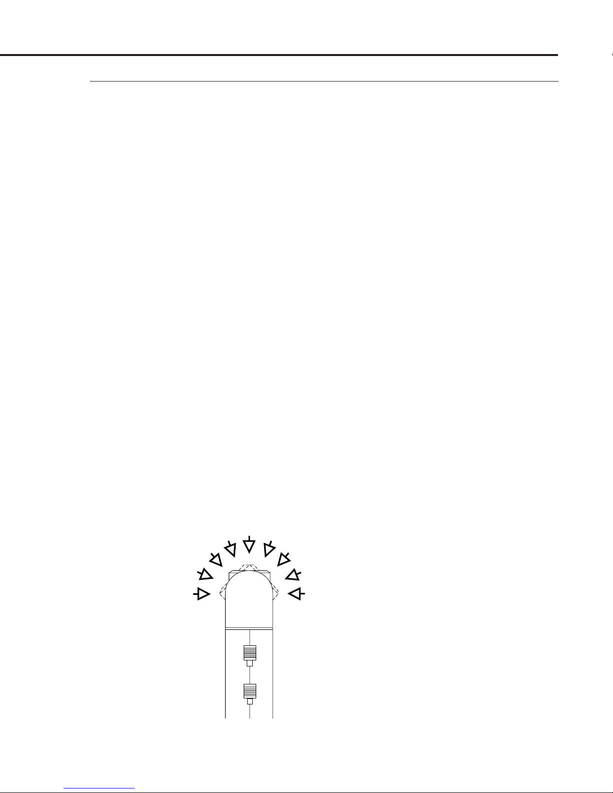
Figure 1-1
Tiltable Display is Viewed
from any Angle
Page 1
Page 3
MAS Instruction Manual
CAUTION! Any application whatsoever related to humanCAUTION! Any application whatsoever related to human
CAUTION! Any application whatsoever related to human
CAUTION! Any application whatsoever related to humanCAUTION! Any application whatsoever related to human
respiration must have the written consent of Koboldrespiration must have the written consent of Kobold
respiration must have the written consent of Kobold
respiration must have the written consent of Koboldrespiration must have the written consent of Kobold
Instruments Inc.Instruments Inc.
Instruments Inc.
Instruments Inc.Instruments Inc.
The versatile MAS Flowmeter digitally displays the mass flow
rate directly in engineering units or percent of full scale. The
display is tiltable over 180° for easy viewing and can be removed
for remote mounting on a front panel.
The Kobold MAS directly monitors the mass flow rate of the gas.
This means it measures molecular flow – the measurement quality
of direct concern in most applications, such as human respiration,
chemical processes, combustion, and heating or cooling. No
temperature or pressure corrections are required, as in the case of
most other flow monitoring devices like rotameters, turbine meters,
and orifice plates.
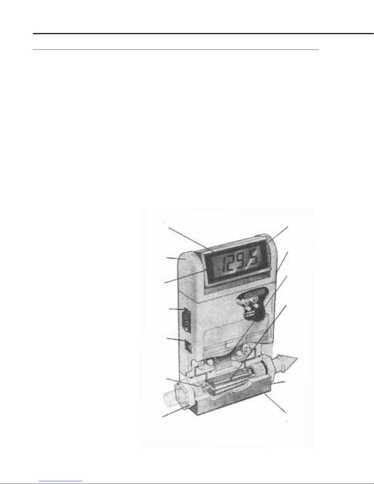
Figure 1-2
MAS Operation
and Features
Direct Monitoring of
Mass Flow.
No temperature or
pressure corrections
required.
Unexcelled Performance.
● ±
1.5% accuracy.
●
0.5% repeatability.
●
2 second response time
Tiltable Display.
9 positions provide easy
viewing from any angle.
Connector.
9-Pin "D" Sub-type. Has
0-5 VDC or 4-20 mA
(optional) output signal
linearly proportional to
mass flow rate.
Input Power Jack.
Accepts 12 to15 VDC or
24 VDC input power from
Kobold power supply or
customer supplied power.
Inlet Screen.
Filters out particulates.
Easily removable.
Digital Display.
Gives mass flow
rate in engineering
units.
Zero and Span
Potentiometers.
Adjustable from
outside of enclosure.
Patented Sensor
Tube.
Straight, large-I.D.
sensor tube is easy
to clean.
Patented Laminar
Flow Bypass.
Provides a variety of
flow ranges. Unique
cutouts make range
changes easy.
Flow Body.
Corrosion resistant
plastic or stainless
steel.
FKM
rings standard.
"O"-
Inlet/Outlet Fittings.
Available with Female
NPT or Swagelok®
style compression
fittings.
Page 2
Mounting Holes.
The MAS mounts in any
position for convenience
of installation.
Page 4
The MAS Flowmeter is a transducer requiring a 12-15 VDC (24
VDC optional) external power source. A 0-5 VDC or optional 4-20
mA output singal linearly proportional to gas mass flow rate is
provided for recording, data-logging, or control. A 9-Pin “D” subconnector is provided for power input and signal output. The MAS
is available in several basic configurations with either
(female) or
1
/4 to 1/2 inch O.D. tube compression inlet/outlet fittings,
1
/4 inch NPT
with or without the digital display, or the optional power supply.
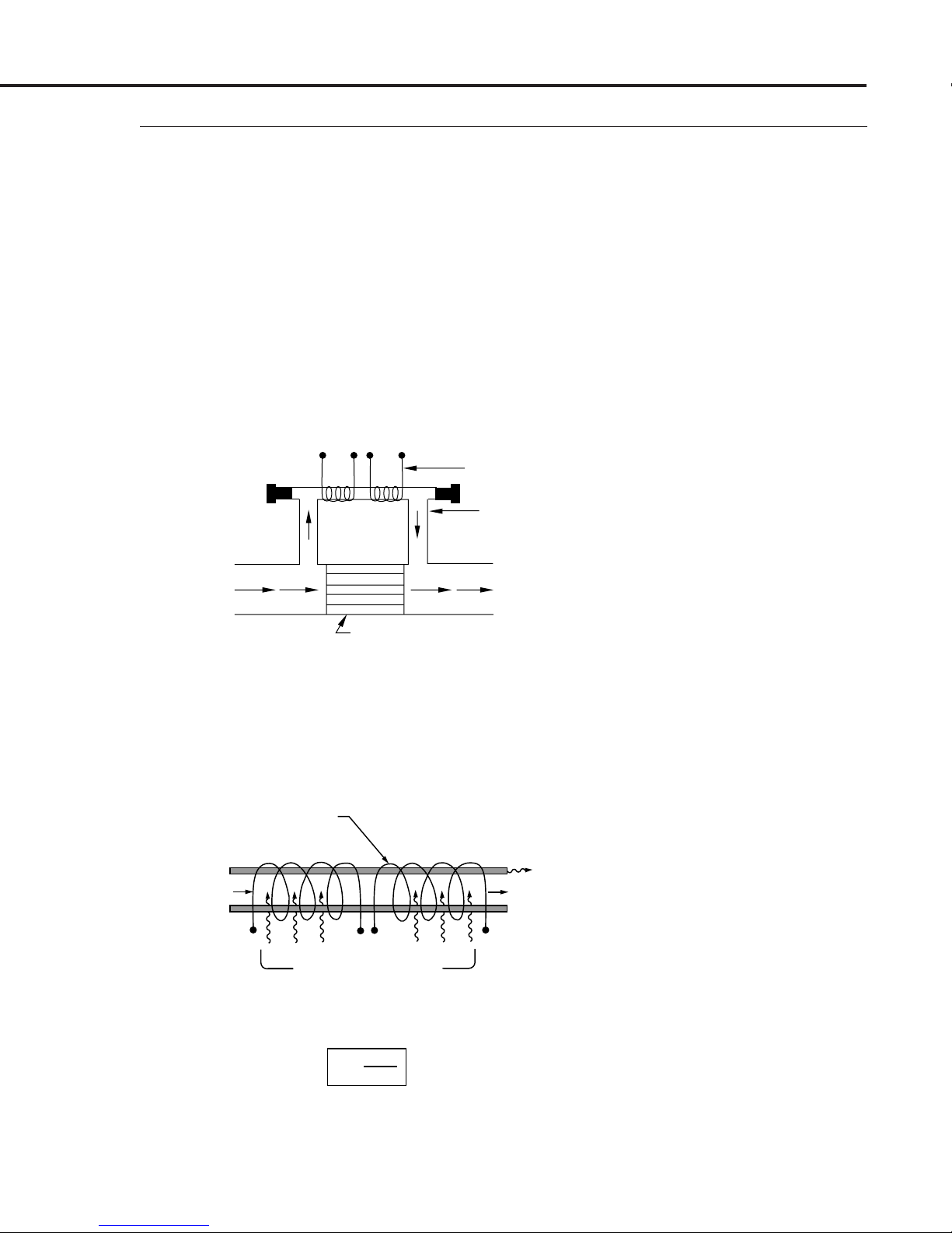
Gas enters the MAS flow body and divides into two flow paths.
Most of the flow goes through the laminar flow bypass. This creates
a pressure drop that forces a small fraction of the flow through the
sensor tube.
TWO COILS
MAS Instruction Manual
1.2
Principle of
Operation
SENSOR
TUBE
m
•
m
1
P
1
•
•
m
2
P
2
LAMINAR FLOW BYPASS
The patented* straight sensor tube is mounted parallel to the
bypass flow path. Since both paths are perfectly laminar, the ratio
of the total flow (
˙
m
) to the sensed flow (
˙
m
) is constant. Two
1
resistance temperature detector (RTD) coils around the sensor
tube direct a constant amount of heat into the gas stream.
RTD COILS
, T
R
1
1
·
m
1
R2, T
2
H
0
Figure 1-3
Two Flow Paths
CONSTANT HEAT, H
FIRST LAW OF THERMODYNAMICS
(HEAT IN = HEAT OUT)
H = m·
*U.S. Patent No. 4,487,062.
(T2 – T1) + H
1 Cp
H–H
m· =
Cp∆T
Figure 1-4
Measuring Sensor Flow
0
0
Page 3
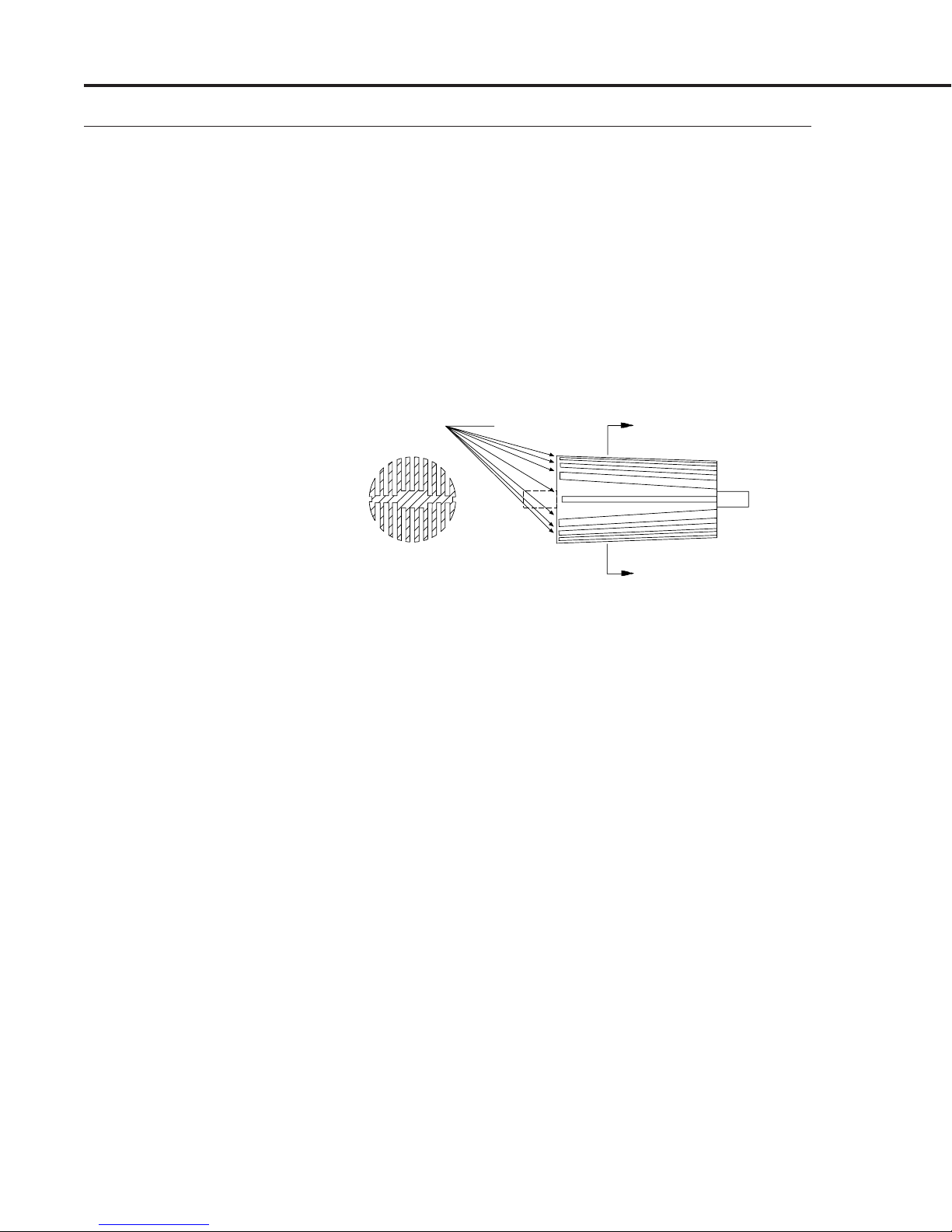
Page 5
MAS Instruction Manual
A
A
“GATES”
SECT. A-A
Figure 1-5
Changing Flow Ranges
is Easy with MAS’s
Patented Bypass
In actual operation, the gas mass flow carries heat from the
upstream coil to the downstream coil. The resulting temperature
difference T
is detected by the RTD coils and gives the output
2–T1
signal. Since the molecules of the gas carry away the heat, the
output signal is directly and linearly proportional to gas mass
flow.
MAS's patented laminar flow bypass makes changing of flow
ranges easy with the proper calibration facilities. Each of the two
bypasses in the optional Laminar Flow Bypass Set has a
combination of rectangular slots along its circumference as shown
in Figure 1-5 below.
1.3
Specifications
To change the flow range of your MAS, follow the instructions
provided with the Kobold Model EL Laminar Flow Bypass Set and
cut away the “gate(s)” leading to the right combination of laminar
flow paths in one of the two bypasses. This procedure requires
proper calibration facilities and minimal skill in electronics.
FLOW RANGES
_________________________________________________________________
_________________________________________________________________
_________________________________________________________________
Flow ranges specified are for an equivalent flow of nitrogen at 760 mm
Hg and 21°C (70°F). Other ranges are available.
GASES
Most gases; check compatibility with wetted materials; specify
when ordering.
Code SCCM Code S LM
01 0-10 07 0-1
02 0-20 08 0-2
03 0-50 09 0-5
04 0-100 10 0-10
05 0-200 11 0-20
06 0-500 12 0-30
13 0-40
DISPLAY
Page 4
31/2 digit LCD (0.5 inches tall); removable for remote mounting.
Page 6

OUTPUT SIGNAL
Linear 0-5 VDC standard, 1000 ohms min. load impedance; 4-20
mA optional, 50 to 500 ohms loop resistance.
POWER REQUIREMENTS
12-15 VDC nominal; 100 mA max (24 VDC optional, specify when
ordering).
ACCURACY
±1.5% of full scale including linearity over 15 to 25 °C and 5 to 60
psia (0.35 to 4.2 kg/cm
2
); with special calibration ±1% of full scale
accuracy at a specific temperature and pressure is available.
REPEATABILITY
±0.5% of full scale.
TEMPERATURE COEFFICIENT
0.15% of full scale per °C, or better.
MAS Instruction Manual
PRESSURE COEFFICIENT
0.01% of full scale per psi (0.07 kg/cm2), or better.
RESPONSE TIME
800 ms time constant; 2 seconds (typical) to within ±2% of final
value over 25 to 100% of full scale.
PRESSURE DROP
____________________________________________________________
Typical Maximum Pressure Drop
_____________________________________________________________
Flow Rates (cm of Water)
100 SCCM .025
1 SLM .454
1 0 SL M 6.00
2 0 S L M 23.83
3 0 S L M 45.60
___________________________________________________________
4 0 S L M 83.36
GAS PRESSURE
150 psi (10 kg/cm2) gauge max; 20 psi (1.4 kg/cm2) gauge optimum.
LEAK INTEGRITY
–4
1×10
SCCS of helium max to outside environment.
GAS AND AMBIENT TEMPERATURE
0 to 50 °C.
Page 5
Page 7
MAS Instruction Manual
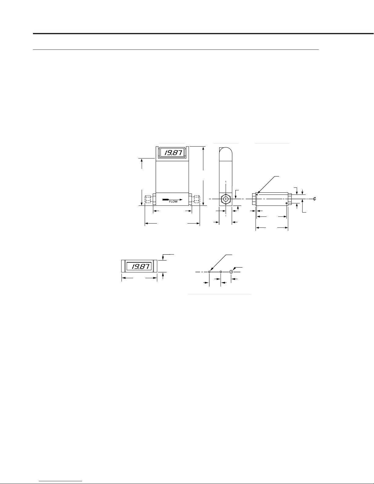
1.15
(29.21)
3.05
(77.47)
4.16
(105.66)
(WITHOUT
DISPLAY)
5.38
(136.65)
3.50 (88.90)
1
/4" NPT
6.68 (169.67)
1
/4" SWAGELOCK
®
ALL DIMENSIONS IN INCHES
0.58
(14.73)
1.16
(29.46)
0.56
(14.22)
6-32 X 0.15 DP.
(SELF TAPPING)
0.75 (19.05)
0.38
(9.65)
0.13 (3.30)
2.75
(69.85)
3.00
(76.20)
0.125 DIA. THRU PANEL-2 PLACES;
FOR TWO 4-40 FLAT HEAD SCREWS
0.25 DIA. THRU; FOR 4 WIRES
0.88 (22.35)
1.00 (25.4)
PANEL MOUNTING HOLES
DIMENSIONS IN INCHES
(DIMENSIONS IN MILLIMETERS IN PARENTHESES)
SIDE VIEW
END VIEW
BOTTOM VIEW
Dimensions
WETTED MATERIALS
5% glass-filled Polyamide 6/6; 316 stainless steel; FKM “O”-
rings standard, FFKM and silicone O-rings optional.
WEIGHT
2 lb. (0.9 kg) net; 3 lb. (1.4 kg) shipping.
Page 6
Page 8

MAS Instruction Manual
Many options are available for your Kobold MAS. Please consult
Kobold’s current Price List for the respective prices.
V4 (Optional) 4-20 mA output signal
C( ) Cable assembly, specify cable type (round or ribbon) and
length
T2 1-5 Channel Power Supply, in NEMA Box, 115 VAC
T4 1-5 Channel Power Supply, in NEMA Box, 230 VAC
T5 Power Supply, for one channel, 110 VAC
T6 Power Supply, for one channel, 230 VAC
UV Upstream valve
DV Downstream valve
M S Replacement mass flow sensor, includes “O”-rings and
mounting flanges
OV
Complete set of FKM “O”-rings
T P Tip plate for electrical enclosure
RD–( ) Remote display
1.4
Options
* U.S. and foreign patents pending.
® Registered trademarks:
Swagelok, VCO, VCR–Crawford Fitting Co.
Page 7
Page 9

MAS Instruction Manual
2
INSTALLATION
2.1
Receipt of Your
MAS
2.2
Return Shipment
When
packing carton for damage incurred in shipment. If the packing
carton is damaged, the local carrier should be notified at once
regarding their liability. Kobold’s Customer Service Department
should also be notified immediately.
Customer Service Phone Number:
For our customers other than the USA, Canada and Mexico please
call the distributor from whom you purchased your MAS or call our
head office in Germany for the Kobold location nearest you:
Remove the packing slip from its envelope and verify that the
carton contains all parts listed. Inspect the carton and packing
material thoroughly to ensure that no spare parts or accessories
are mistakenly discarded. In case of shortages, please contact
Customer Service at the above phone number, or they may be
contacted in writing at the address listed in the next section.
Please do not return any equipment without a Return Material
Authorization, which is obtained from the Customer Service
Department. Information describing the problem, corrective action
or work to be performed at the factory, the purchase order number
that the equipment was purchased under, and the name of the
person to contact must be included with the returned equipment.
The use of a Return Material Authorization is for your benefit. It
makes the proper service and return of your equipment much
easier to accomplish.
Return shipping address:
the equipment is received, carefully check the outside
USA (412) 788-2830, or Fax (412) 788-4890
Germany 49(0)61-92-29-90 or Fax 49(0)61-92-23-398
Non-North American customers may contact the KOBOLD
Messring GmbH Customer Service Department Technical
Assistance at:
NOTE: Equipment returned for repair that is found to be completely
operational will be subject to the current “no problem found”
billing rate.
Page 8
USA KOBOLD INSTRUMENTS INC.
1801 Parkway View Drive
Pittsburgh, PA 15205
Europe KOBOLD MESSRING GmbH
Nordring 22-24
65719 Hofheim/Ts.
Germany
Page 10

CAUTION! The maximum pressure and temperature in theCAUTION! The maximum pressure and temperature in the
CAUTION! The maximum pressure and temperature in the
CAUTION! The maximum pressure and temperature in theCAUTION! The maximum pressure and temperature in the
flow line in which your MAS is to be installed must notflow line in which your MAS is to be installed must not
flow line in which your MAS is to be installed must not
flow line in which your MAS is to be installed must notflow line in which your MAS is to be installed must not
exceed 150 psig (10 kg/cmexceed 150 psig (10 kg/cm
exceed 150 psig (10 kg/cm
exceed 150 psig (10 kg/cmexceed 150 psig (10 kg/cm
respectively.respectively.
respectively.
respectively.respectively.
22
2
22
gauge) or 150 gauge) or 150
gauge) or 150°
gauge) or 150 gauge) or 150
F (65F (65
F (65°
F (65F (65
C),C),
C),
C),C),
MAS Instruction Manual
In order to ensure a successful installation, inlet and outlet tubing
or piping should be in a clean state prior to plumbing your MAS to
the system. MAS is applicable to
clean gas onlyclean gas only
clean gas only because
clean gas onlyclean gas only
particulates and other foreign matter may clog the sensor tube and
laminar flow element over a period of time. If the gas contains
particulate matter, install a high-efficiency, 50 to 100 micron, inline filter upstream of the MAS.
Do not locate the MAS Flowmeter in areas subject to sudden
temperature changes, moisture, drafts, or near equipment radiating
significant amounts of heat. Allow adequate space for cable
connectors and wiring. If your MAS is to be mounted in other than
a horizontal position, the zero will need adjustment. See Section
5.2, R
CAUTION! Be sure the arrow on the side of the transducerCAUTION! Be sure the arrow on the side of the transducer
CAUTION! Be sure the arrow on the side of the transducer
CAUTION! Be sure the arrow on the side of the transducerCAUTION! Be sure the arrow on the side of the transducer
points in the direction of flow.points in the direction of flow.
points in the direction of flow.
points in the direction of flow.points in the direction of flow.
ECALIBRATION OVER THE SAME FLOW RANGE.
The MAS may be mounted to a chassis with two 6-32 self-tapping
screws. See Section 1.3, S
PECIFICATIONS, for hole dimensions.
2.3
Mechanical
Installation
Your MAS is supplied with either
1
/4 , 3/8 or 1/2 inch compression inlet and outlet fittings. These
or
1
/4 inch female NPT (standard)
fittings should not be removed unless your MAS is being cleaned
®
or calibrated for a new flow range. VCO
1
available on special order.
/4-inch pipe requires a good quality
or VCR® fittings are
paste pipe thread sealant and should be installed in the inlet and
1
outlet fittings 1
CAUTION! Over-tightening will crack the fittings andCAUTION! Over-tightening will crack the fittings and
CAUTION! Over-tightening will crack the fittings and
CAUTION! Over-tightening will crack the fittings andCAUTION! Over-tightening will crack the fittings and
shift calibration.shift calibration.
shift calibration.
shift calibration.shift calibration.
/2 turns beyond hand-tight.
For the first installation of compression fittings, simply insert the
tubing into the fitting. Make sure that the tubing rests firmly on
the shoulder of the fitting and that the nut is hand-tight. Scribe the
nut at the six o’clock position. While holding the fitting body steady
1
with a back-up wrench, tighten the nut 1
/4 turns, watching the
scribe mark make one complete revolution and continue to the nine
o’clock position. After this, the fitting can be reconnected by
snugging with a wrench. Do not fail to use a back-up wrench or the
inlet fitting may be damaged.
2.4
Plumbing
Connections
Page 9
Page 11
MAS Instruction Manual
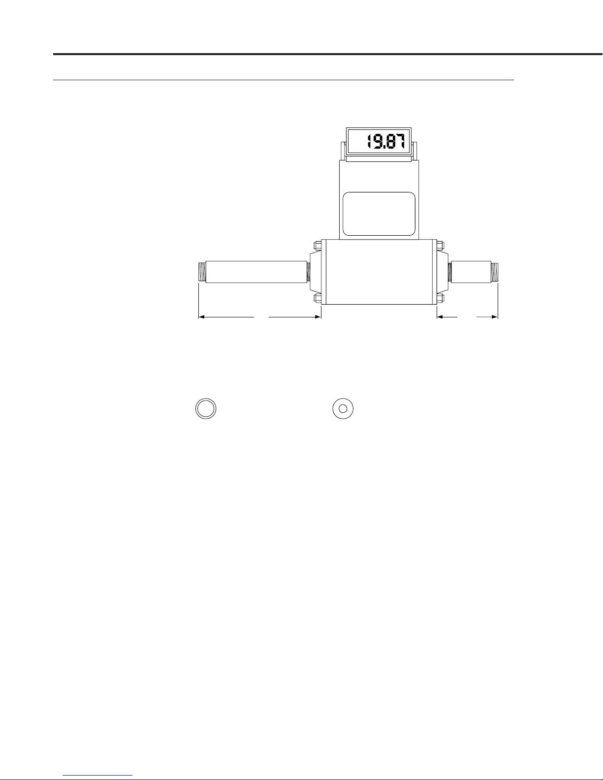
Figure 2-1
Plumbing Requirements
for Model’s 1100/2100
FLOW
➡
5.0"
(127 mm)
1
/2" NPT PIPE
(10 DIAMETERS)
EXAMPLE: Cross Section
CORRECT
1
/2" NPT pipe for
1
/2" NPT flow body
CAUTION! Do not mix or interchange parts of tube fittingsCAUTION! Do not mix or interchange parts of tube fittings
CAUTION! Do not mix or interchange parts of tube fittings
CAUTION! Do not mix or interchange parts of tube fittingsCAUTION! Do not mix or interchange parts of tube fittings
made by different manufacturers.made by different manufacturers.
made by different manufacturers.
made by different manufacturers.made by different manufacturers.
INCORRECT
Avoid use of compression
fitting on inlet of flow body. The
reduction of internal diameter of
the fitting results in a “jet”, creating
noise and affecting calibration.
DO NOT reduce down right at the
inlet with
1
/4" pipe.
2.50"
(63.5 mm)
1
/2" NPT PIPE
(5 DIAMETERS)
Finally, check the system’s entire flow path thoroughly for leaks
before proceeding to Section 3, O
CAUTION! All instruments are leak-tested prior to shipping.CAUTION! All instruments are leak-tested prior to shipping.
CAUTION! All instruments are leak-tested prior to shipping.
CAUTION! All instruments are leak-tested prior to shipping.CAUTION! All instruments are leak-tested prior to shipping.
To check your installation, test the fittings only. Do not useTo check your installation, test the fittings only. Do not use
To check your installation, test the fittings only. Do not use
To check your installation, test the fittings only. Do not useTo check your installation, test the fittings only. Do not use
liquid leak detectors such as Snoop® to search for leaksliquid leak detectors such as Snoop® to search for leaks
liquid leak detectors such as Snoop® to search for leaks
liquid leak detectors such as Snoop® to search for leaksliquid leak detectors such as Snoop® to search for leaks
inside or outside the MAS. Instead, monitor pressureinside or outside the MAS. Instead, monitor pressure
inside or outside the MAS. Instead, monitor pressure
inside or outside the MAS. Instead, monitor pressureinside or outside the MAS. Instead, monitor pressure
decay.decay.
decay.
decay.decay.
Page 10
PERATION.
Page 12
MAS Instruction Manual
MAS flowmeters require a single +12 to +15 VDC power supply
capable of providing a minimum current of 100 mA. The MAS can
also be configured for +24 VDC power at 100 mA.
Operating power input is via either the DC power jack or the 9-pin
“D” connector on the side of the enclosure. Kobold offers the Model
MAS-5000 single channel power supplies for single transducer
applications and the Model MAS-5100 for powering up to eight
transducers through the "D" connector.
CAUTION! Do not supply + DC power at the “D” connectorCAUTION! Do not supply + DC power at the “D” connector
CAUTION! Do not supply + DC power at the “D” connector
CAUTION! Do not supply + DC power at the “D” connectorCAUTION! Do not supply + DC power at the “D” connector
while using an MAS-5000 power supply at the DC powerwhile using an MAS-5000 power supply at the DC power
while using an MAS-5000 power supply at the DC power
while using an MAS-5000 power supply at the DC powerwhile using an MAS-5000 power supply at the DC power
jack. Do not plug power connector into DB9 connector.jack. Do not plug power connector into DB9 connector.
jack. Do not plug power connector into DB9 connector.
jack. Do not plug power connector into DB9 connector.jack. Do not plug power connector into DB9 connector.
Damage to electronics will result.Damage to electronics will result.
Damage to electronics will result.
Damage to electronics will result.Damage to electronics will result.
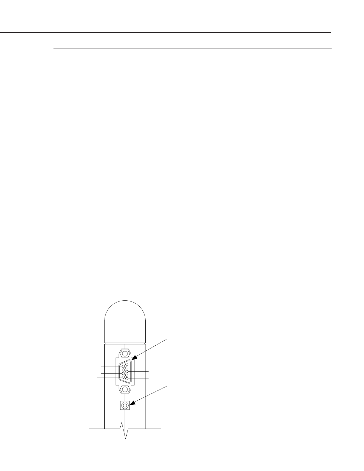
The standard MAS is provided with a 9-pin “D” sub type connector
located on the side of the MAS enclosure as shown in Figure 2-2.
The pin numbers for this “D” connector are also shown in Figure 22, and the pin assignments are given in Table 2-1 on the next page.
The output signal is obtained from the 9-pin “D” connector. A 0 to
5 VDC output signal linearly proportional to gas mass flow rate is
standard. A 4-20 mA current loop signal is optionally available.
The mating connector is included.
2.5
Electrical
Connections
2.5.1
9-Pin “D”-Connector
Pin Assignments
When the MAS is configured for a remote display, connections are
made via the 9-pin “D” connector. Power connections for the
display and transducer are shared in this mode unless the accessory
MAS-5000 power supply is used.
“D” CONNECTOR
7
8
9
6
1
2
3
4
5
DC POWER JACK
Figure 2-2
“D” Connector and DC
Power Jack Location and
Number Assignments
Page 11
Page 13
MAS Instruction Manual
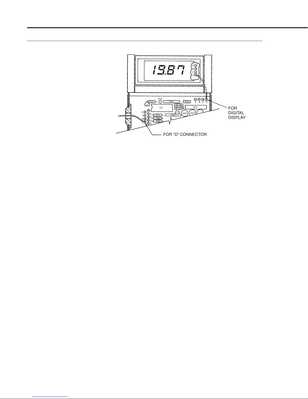
Figure 2-3
Printed Circuit Board
Input/Output Solder Pad
Assignments (wires shown
are typical)
Table 2-1
The following connection points can be made through the “D”
connector or, in OEM applications, made through the circuit board
solder pad connections.
The display pad connections are shown for applications requiring
remote mounting of the digital display. The letters appear on the
display circuit board and are shown in Figure 2-3.
___________________________________________________________
____________________________________________________________
Pin No. Function Display Pad
1 No Connection N/A
2 Signal Common N/A
3 0 to +5 VDC Flow Signal N/A
4 + Power Supply (12 or 24 VDC)
*1, *2
(A)
5 Remote Display Flow Signal (D)
6 Remote Display Reference (C)
7 Power Common (B)
8 4 to 20 mA Return (Common) N/A
____________________________________________________________
9 4 to 20 mA Output N/A
NOTE: the numbers on the connector plug may not agree with the
numbering system as it appears on our Figure 2-2 (on previous
page). It is important to make sure that the proper wires are in the
proper location rather than the proper number. Most connectors
utilize a standard numbering scheme but there are a few that do
not.
The remote display connects through the 9-pin “D” connector only.
The pads A-D in the top right of the main circuit board are for
integral display mounting only.
*1 Power supply voltage must be specified at time of order. Operating a 12 VDC meter at
*2 Do not supply + DC power at the “D” connector while using a power supply at the DC
Page 12
24 VDC will cause damage. Running a 24 VDC meter at 12 VDC will result in faulty
operation.
power jack. Both supplies may be damaged.
Page 14
MAS Instruction Manual
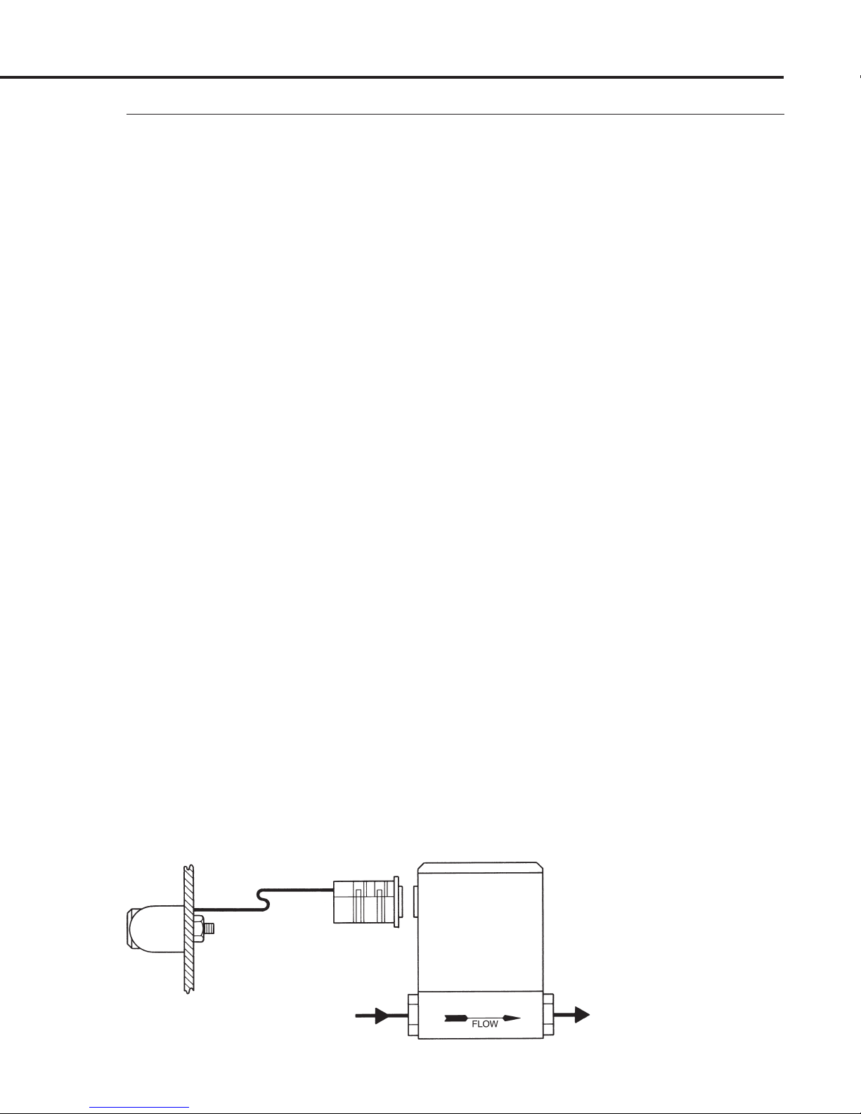
As shown in Figure 2-4, the digital display on your MAS may be
removed and mounted remotely on a front panel. The MAS
transducer is mounted at any convenient location in your system.
Remote installation is not recommended unless you possess the
proper soldering tools and skills to accomplish the job. Remote
installation of the digital display is accomplished by following
these steps:
1. Remove the digital display from your MAS by following the
procedure described in Section 2.5.3, OEM E
TIONS.
LECTRICAL C ONNEC-
2. Gain access to the printed circuit board (PCB) also by following
the procedure in Section 2.5.3, OEM E
LECTRICAL C ONNECTIONS.
3. Very carefully unsolder the four short leads from the PCB to the
display.
4. Gain access to the display circuit board by removing the two
snap rings (No. 36) and opening the “clam shell” display enclosure. Remove the four short wires by carefully unsoldering.
Solder the longer four wires (26AWG, 100 ft. max shielded cable
recommended) to the digital display and solder the other ends
to the appropriate pin numbers of the 9-pin “D” connector as
shown in Figure 2-3 and Table 2-1 (on previous page).
2.5.2
Remote Installation of
Digital Display
5. Reassemble the MAS, replacing the display base (No. 35) with
the Model TP Plain Top Cover (No. 28).
6. Make the necessary plumbing connections to the unit.
7. Mount the digital display as shown in Figure 2-4 referring to the
panel mounting hole dimensions in Section 1.3, S
PECIFICATIONS.
Figure 2-4
Remote Installation of
Digital Display
Page 13
Page 15

MAS Instruction Manual
2.5.3
OEM Electrical
Connections
The OEM version MAS flowmeter has an electrical port (hole) on
its side for electrical input/outputs. This port is just above the
input power jack (see Figure 2-2). Wires entering the MAS via this
port are soldered to the printed circuit board as shown in Figure 2-
3. The solder pad assignments are given in Table 2-1.
How to Gain Access to the MAS’s Printed Circuit Board (PCB):
To gain access to the PCB to make the solder connections, please
refer to the exploded view in Appendix A and follow these simple
steps.
1. If your MAS has the digital display:
(a) First, remove the display by carefully rotating the display
until it hits the top plate. Slowly continue to rotate until this
lever arm action snaps out the two yokes holding the display
(Nos. 30). Use extra caution during this operation as excessive
force will break the delicate wire connections. Carefully move
the display assembly to expose the two screws securing the
display base (No. 35). Do not exert excessive force on the display
while rotating as doing so could crack the LCD display.
(b) Next, remove the two screws (Nos. 21) in the display base
(No. 35) and the two screws (also Nos. 21) in the back of the
enclosure (No. 10).
2.5.4
Using Kobold’s Single,
Dual, and Flo-Box™
Electronics
(c) The top, front, and back sides of the enclosure can now be
removed, (the front slides out towards you and perpendicular to
the flow path) exposing the PCB.
2. If your MAS does not have the digital display:
(a) Remove the label (No. 29) from the plain top cover (No. 28)
to expose the two screws (Nos. 21).
(b) Then follow steps 1(b) and 1(c) above.
To reassemble, just reverse the process.
For applications requiring flow totalization or alarms simply
order the optional Model EC-( ) cable to connect to the rear panel
of Kobold Instruments’ Single-Channel, Dual-Channel, or FloBox (1-5 Channels) Electronics. The Kobold electronics will provide
you with a selectable digital readout for each channel, input power,
high, low, or window alarms, and optional flow totalization.
Page 14
Page 16

MAS Instruction Manual
Quick operating instructions are given on the first page of this
manual.
Following are important notes and comments regarding the Quick
Operating Instructions.
NOTE 1 R
EFERENCING THE FLOW RATE TO OTHER TEMPERATURE AND
PRESSURE CONDITIONS:
The gas flow rate output of your MAS is referenced to “standard”
conditions of 21°C (70°F) and 760 mm of mercury (1 atmosphere),
unless you have specified otherwise. Be sure you know the reference
conditions of your MAS, because it may make a difference if you are
comparing the output of the MAS with another type of flow meter.
For example, the output reading of the MAS will be approximately
7% lower if it is referenced to 0°C rather than 21°C. Appendix B
shows how to convert the flow rate output of your MAS to other
standard conditions and how to find the flow rate referenced to the
actual temperature and pressure conditions in the pipe where your
MAS is located.
NOTE 2 A
CCURACY:
The standard accuracy of the MAS is ±1.5% of full scale. The ±1.5%
of full scale accuracy means the 0-5 VDC output signal is accurate
to within ±0.1 VDC, and the 4-20 mA output is accurate to within
±0.4 mA. This means, for example, that the output signal for zero
flow can be as much as ± 0.1 VDC or ±0.4 mA. Please note if you get
an output signal at zero flow (as long as it is within either of these
two ranges) it does not mean your MAS is malfunctioning. For
MAS’s with the digital readout, the accuracy is simply 1.5% times
the full scale flow rate listed on your MAS’s front label. For
example, if your full scale is 10 SLM, the digital readout will be
accurate to ±0.2 SLM, and the reading at zero flow may be as much
as ±0.2 SLM and still be within the stated accuracy specification.
3
OPERATION
3.1
Quick Operating
Instructions
3.2
Notes to Operating
Instructions
NOTE 3 O
VERRANGING:
If the flow rate exceeds the full scale range listed on your MAS’s
front label, the output signal and digital display (if you have it) will
read a higher value.
The MAS has not been calibrated for overranged flows and probably
will be both non-linear and inaccurate. If the supply voltage is only
12 VDC, the overranged reading may only exceed the full scale
reading by 10% maximum. If the supply voltage is higher, such as
with the 24 VDC option, then the output can exceed full scale by as
much as 50%, or more. If you have the digital display, the display
can not exceed the four digits 1999. If the flow rate exceeds 1999 the
Page 15
Page 17

MAS Instruction Manual
right most digits will blank and only the left-hand “1” will appear
on the display.
Overrange conditions are indicated by the display and/or output
going to a high level, above the full scale range. After the overrange
condition has been removed, it may take several seconds for the
MAS to recover and resume normal operation. This will not harm
the instrument.
NOTE 4 O
PTIONAL 4-20 mA OUTPUT S IGNAL:
The 4-20 mA output signal current flows from the 4-20 mA output
pin on the “D” connector through the load (50 to 500 ohms) to
ground (see Section 2.5.1, 9-P
IN “D” CONNECTOR P IN A SSIGNMENTS).
Figures 3-1 and 3-2 illustrate single and multiple installations
with current loop outputs.
NOTE 5 Z
ERO AND SPAN ADJUSTMENTS:
The zero and span potentiometers are accessed through marked
ports on the right side of your MAS. If your zero output is more than
±1.5% of full scale, you may adjust the zero potentiometer when
you are absolutely certain that you have zero flow.
Since the output does not indicate negative numbers, it is necessary
to adjust down from a slightly positive reading. Slowly rotate the
zero pot clockwise until a positive reading is indicated. To complete
the zero adjustment, slowly turn the pot counterclockwise until
zero is reached.
Normally, span adjustments are not made unless you areNormally, span adjustments are not made unless you are
Normally, span adjustments are not made unless you are
Normally, span adjustments are not made unless you areNormally, span adjustments are not made unless you are
calibrating your MAS, as described in Section 5. calibrating your MAS, as described in Section 5.
calibrating your MAS, as described in Section 5. The span
calibrating your MAS, as described in Section 5. calibrating your MAS, as described in Section 5.
adjustment should not be used unless you have a known precise
non-zero flow rate that you wish to match.
NOTE 6 A
Unless specified otherwise, your MAS has been calibrated for
installation with the flow direction in the horizontal plane (±15°)
with the enclosure facing upward. If your actual installation
orientation is different, you will have to make a small zero
adjustment.
Page 16
TTITUDE:
Page 18

MAS Instruction Manual
Figure 3-1
Single Unit 4-20 Hookup
Figure 3-2
Multiple Installation
4-20 Hookup
Page 17
Page 19

MAS Instruction Manual
4
MAINTENANCE
4.1
General Statement
4.2
Flow Path Cleaning
Your MAS essentially requires no maintenance and has no regular
maintenance schedule, other than periodic flow path cleaning if
the gas is dirty. Calibrations may be scheduled once or twice
yearly, depending on the accuracy to be maintained, or as needed.
It is recommended that your MAS be returned to KoboldIt is recommended that your MAS be returned to Kobold
It is recommended that your MAS be returned to Kobold
It is recommended that your MAS be returned to KoboldIt is recommended that your MAS be returned to Kobold
Instruments if cleaning, repair, or recalibration are needed.Instruments if cleaning, repair, or recalibration are needed.
Instruments if cleaning, repair, or recalibration are needed.
Instruments if cleaning, repair, or recalibration are needed.Instruments if cleaning, repair, or recalibration are needed.
This is usually your most cost-effective and reliableThis is usually your most cost-effective and reliable
This is usually your most cost-effective and reliable
This is usually your most cost-effective and reliableThis is usually your most cost-effective and reliable
alternative.alternative.
alternative.
alternative.alternative.
The flow path (wetted parts) of the MAS are 5% glass-filled
Polyamide 6/6; 316 stainless steel (sensor tub e); and FKM “O”-rings
(standard).
CAUTION! IF YOU WISH TO CLEAN YOUR MAS PURGECAUTION! IF YOU WISH TO CLEAN YOUR MAS PURGE
CAUTION! IF YOU WISH TO CLEAN YOUR MAS PURGE
CAUTION! IF YOU WISH TO CLEAN YOUR MAS PURGECAUTION! IF YOU WISH TO CLEAN YOUR MAS PURGE
IT THOROUGHLY BEFORE DISCONNECTING FROM THEIT THOROUGHLY BEFORE DISCONNECTING FROM THE
IT THOROUGHLY BEFORE DISCONNECTING FROM THE
IT THOROUGHLY BEFORE DISCONNECTING FROM THEIT THOROUGHLY BEFORE DISCONNECTING FROM THE
GAS LINE WHEN TOXIC OR CORROSIVE GASES AREGAS LINE WHEN TOXIC OR CORROSIVE GASES ARE
GAS LINE WHEN TOXIC OR CORROSIVE GASES ARE
GAS LINE WHEN TOXIC OR CORROSIVE GASES AREGAS LINE WHEN TOXIC OR CORROSIVE GASES ARE
USED. NEVER RETURN AN MAS TO KOBOLDUSED. NEVER RETURN AN MAS TO KOBOLD
USED. NEVER RETURN AN MAS TO KOBOLD
USED. NEVER RETURN AN MAS TO KOBOLDUSED. NEVER RETURN AN MAS TO KOBOLD
INSTRUMENTS OR ANY OTHER REPAIR ORINSTRUMENTS OR ANY OTHER REPAIR OR
INSTRUMENTS OR ANY OTHER REPAIR OR
INSTRUMENTS OR ANY OTHER REPAIR ORINSTRUMENTS OR ANY OTHER REPAIR OR
CALIBRATION FACILITY WITHOUT FULLYCALIBRATION FACILITY WITHOUT FULLY
CALIBRATION FACILITY WITHOUT FULLY
CALIBRATION FACILITY WITHOUT FULLYCALIBRATION FACILITY WITHOUT FULLY
NEUTRALIZING ANY TOXIC GASES TRAPPED INSIDE.NEUTRALIZING ANY TOXIC GASES TRAPPED INSIDE.
NEUTRALIZING ANY TOXIC GASES TRAPPED INSIDE.
NEUTRALIZING ANY TOXIC GASES TRAPPED INSIDE.NEUTRALIZING ANY TOXIC GASES TRAPPED INSIDE.
4.2.1
Inlet and Outlet Screen
4.2.2
Laminar Flow Element
(LFE)
Please refer to the exploded drawing of the MAS transducer in
Appendix A when using the following procedures. All cleaning of
the flow path can be accomplished with Freon™, alcohol, or any
cleaner safe for the listed materials.
Remove inlet and outlet fittings (Nos. 13), pull out the LFE holddowns (Nos. 12) and either replace or clean the inlet and outlet
screens (Nos. 14).
Remove the inlet and outlet fittings as in Section 4.2.1, I
NLET AND
OUTLET S CREEN. The LFE (either No. 24 or No. 25) has a slightly
tapered shape with the larger diameter upstream (on the inlet
side). To remove the LFE for cleaning, simply push it out the inlet
side from the outlet side using a blunt object which does not mar
the flow channels. A
3
/8" (9 mm) nut driver is perfect for the job.
When cleaning, be sure to carefully clean all active flow channels
in the LFE.
IMPORTANT:IMPORTANT:
IMPORTANT: When reinstalling the LFE it is of utmost
IMPORTANT:IMPORTANT:
importance to press it in the correct distance. Refer to Figure 4-1
for the correct distance.
Page 18
Page 20

MAS Instruction Manual
.60
(15.24)
INLET
.85
(21.59)
(DIMENSIONS IN MILLIMETERS IN PARENTHESES)
CAUTION! Opening the sensor cavity will shift calibra-CAUTION! Opening the sensor cavity will shift calibra-
CAUTION! Opening the sensor cavity will shift calibra-
CAUTION! Opening the sensor cavity will shift calibra-CAUTION! Opening the sensor cavity will shift calibration.tion.
tion.
tion.tion.
DIMENSIONS IN INCHES
.61
(15.49)
OUTLET
.90
(22.86)
Do not remove the PCB Bracket (No. 7) unless it is absolutely
necessary to gain access to the sensor cavity. Doing so will shift
the calibration more than 1.5%. The remaining parts of the flow
path are disassembled as shown in the exploded view in Appendix
A. Note the position of the insulation blanket before removal and
re-install in the same fashion. After removal, the sensor tube (No.
5) can be cleaned by purging, washing with a solvent, or by rodding
out the 0.031 inch (.787 mm) internal diameter tube with a 0.029-
0.030 inch (.737-.762 mm) outside diameter rod or wire or with the
Model CK Cleaning Stylet available from Kobold Instruments. To
maximize the time response of your MAS, Kobold has designed
the sensor tube with thin walls.
extremely careful not to bend the sensor tube or to mar itsextremely careful not to bend the sensor tube or to mar its
extremely careful not to bend the sensor tube or to mar its
extremely careful not to bend the sensor tube or to mar itsextremely careful not to bend the sensor tube or to mar its
inlet or outlet edges.inlet or outlet edges.
inlet or outlet edges.
inlet or outlet edges.inlet or outlet edges.
Therefore, when cleaning, beTherefore, when cleaning, be
Therefore, when cleaning, be
Therefore, when cleaning, beTherefore, when cleaning, be
Figure 4-1
Proper LFE Location
Within The Flow Body
4.2.3
Sensor Tube
It is important when reinstalling the sensor to make sure that no
torque is imparted on the sensor tube. Torque can be eliminated
by using a good quality oxygen compatible grease on the sensor
sealing “O”-rings. The sensor assembly should slide freely into
the cavity flanges without having to twist it. Twisting will impart
undesirable torque on the sensor and could lead to long term
shifting of the zero value. Also, take
disturb or unravel the sensor windings.
EXTREMEEXTREME
EXTREME care to not
EXTREMEEXTREME
Page 19
Page 21

MAS Instruction Manual
5
FLOW
CALIBRATION
5.1
General Flow
Calibration Procedure
5.2
Recalibration Over the
Same Flow Range
Flow calibration of your MAS requires a calibration standard of at
least double accuracy and preferably an order of magnitude better.
NOTE: The factory calibration of your unit was done to MIL-STD45662 A, which has a 4:1 accuracy requirement. Most calibrations
can be done using dry nitrogen and the “K”-factors and gas tables
given in Appendix D. The standard 1.5% calibration of your MAS
is best accomplished with the Kobold Instruments’ Series 100 CalBench™.
Flow recalibration is performed by using the following procedure.
Please refer to the electrical schematics in Appendix B. Calibration
checks and minor adjustments to the zero and full scale may be
made via the access ports in the side of the enclosure. If the
linearity needs adjustment (as may be required when installing a
different laminar flow element bypass to change the range), go to
STEP 4 through 8. If linearity does not need adjustment, complete
only STEPS 1 through 3.
STEP 1 W
ARM-UP: Plug in the MAS to be calibrated and allow at
least 15 minutes warm-up time before attempting any adjustments.
STEP 2 Z
ERO A DJUST: Slide open the zero and span access ports on
the side of your MAS. Be careful to gently slide open and not bend
back access port covers, as bending back may break covers. Using
a voltmeter connected to the meter output pins, adjust the zero
potentiometer (R5) for zero flow (4 mA for 4-20 mA outputs).
STEP 3 C
HECK F ULL S CALE: Generate the full scale flow using a
metering valve in line with the MAS under test. Compare the
indicated flow rate with the flow standard reading. If they agree to
within ±10%, adjust the span potentiometer (R21) for exact
agreement.
If the readings do not agree within ± 10%, attempt to determine the
cause of disagreement. Possibilities are:
a) Partially clogged or dirty sensor tube
b) Wrong or improper use of “K” factor
c) Wrong or improper correction for temperature and pressure
d) Leaks in the system or in the MAS
e) Replacement of parts in the flow path do not exactly match the
original parts
Page 20
Page 22

This completes the calibration procedure. To adjust linearity, go to
STEP 4.
MAS Instruction Manual
STEP 4 A
DJUSTING LINEARITY: First gain access to the printed
circuit board inside the MAS enclosure by using the procedure
described in Section 2.5.3, OEM E
LECTRICAL C ONNECTIONS. Orient
the meter so that the component side of the circuit board is facing
you. Plug in the meter and allow it to warm up for at least 15
minutes.
STEP 5 Z
ERO A DJUST: Connect a voltmeter to the meter output pins
and adjust the zero potentiometer (R5) for zero volts at zero flow (4
mA for 4-20 mA outputs).
___________________________________________________________________________________
_________________________________________________________________________________
INC. DEC. INC. DEC.
J1 0 0 0 J1 [XXXXX] 0 Adjust R25 (50%)
J2 0 0 0 J2 0 [XXXXX] Adjust R27 (75%)
J3 0 0 0 J3 [XXXXX] 0 Adjust R29 (100%)
Linearizer Jumper Array Jumpers Installed
_________________________________________________________________
Linearizer Jumper Array
STEP 6 CALIBRATE 25%: Use the calibration standard to set a flow
rate of 25% of full scale. Adjust the span potentiometer (R21) for
1.25 volts (8 mA for 4-20 mA outputs) at the output of the meter.
Figure 5-1
STEP 7 C
ALIBRATE 50%: Increase the flow rate to 50% of full scale.
If the output is within ± 100 mV, no adjustment is necessary. If the
output is beyond these limits, install a jumper block at J1 in the
appropriate position (increment (INC.) or decrement (DEC.); see
Figure 5-1) and adjust R25 for the proper reading.
STEP 8 C
ALIBRATE 75% AND 100%: Set the flow to 75% of full scale.
If the output is outside the limits set in STEP 7, install a jumper
block in J2 in the proper location and adjust R27 for the correct
reading. Repeat this procedure for 100% flow, using J3 and R9 if
necessary.
NOTE: If the curve being linearized is not monotonic (e.g., jumpers
are in both increment and decrement positions), repeat STEPS 6
through 8 at least one more time.
Page 21
Page 23

MAS Instruction Manual
5.3
Flow Calibration
Over a Different Flow
Range and/or Gas
The procedure for calibrating your MAS over a different flow range
and/or gas is identical to that described in Section 5.2, R
ECALIBRATION
OVER THE S AME F LOW R ANGE, except that the range of the laminar
flow element (LFE) may need changing.
The first step is to determine the equivalent nitrogen flow rate. To
do so, you must first determine your “standard” gas conditions.
21°C (or 70°F) and 760 mm of mercury (1 atmosphere) is standard
for Kobold Instruments. Appendix C is helpful in this regard. You
must then use the K-factor tables in Appendix D.
The next step is to procure from Kobold Instruments the Model EL
Laminar Flow Bypass Set. This set of two patented Model EL
LFE’s covers all ranges from 0-10 SCCM to 0-40 SLM, when the
proper combination of “gates” to the individual laminar flow
channels have been opened (see Section 1.2, P
RINCIPLE OF O PERATION).
The instruction manual for the Model EL LFE’s describes this
procedure in detail.
NOTE: Potentiometer R15 shown in Appendix B is for speed of
response and does not require any adjustment.
Page 22
Page 24

MAS Instruction Manual
When it is suspected that your MAS is not operating correctly, a
few simple checks can be made before dismantling for repair:
1. Make sure there are no leaks in the line.
2. Check that all cables are plugged in and are in good condition.
3. Check that the power supply is in the correct range.
4. Double-check connector pinouts.
This guide is provided to help locate the section of the MAS at
fault. It is not intended to be an all-inclusive repair manual. In the
case of most repairs, your MAS should be returned to the factory
for service.
______________________________________________________________
Possible Corrective
Symptom Cause Action
______________________________________________________________
No output No power Plug in power supply
Clogged sensor Clean or replace sensor
PCB defective Repair or replace PCB
Inlet filter Clean or replace
screen clogged
6
TROUBLE-
SHOOTING
6.1
General
6.2
Troubleshooting Guide
Will not zero Gas leak Find and correct leaks
Application Re-zero meter
requires high
pressure and nonhorizontal mounting
PCB defective Repair or replace
Reads full scale Defective sensor Return to factory
with zero flow for replacement
Gas leak Find and correct leaks
Out of Dirty or clogged Clean or replace sensor
calibration sensor
Change in See “K” factor tables
composition of gas in Appendix D
Gas leak Find and correct leaks
PCB defective Repair or replace
LFE dirty Clean
Inlet filter screen Clean or replace
______________________________________________________________
clogged
Page 23
Page 25

MAS Instruction Manual
Kobold Instruments will provide technical assistance over the
phone to qualified repair personnel. Please call Customer Service
Department, Technical Assistance, (412) 788-2830, Fax (412) 788-
4890. European customers can contact Kobold Messring GmbH for
customer service and technical assistance at 49(0)61-92-29-90,
Fax 49(0)61-92-23-398. Please have your Serial Number and
Model Number when you call.
Page 24
Page 26

MAS Instruction Manual
If your MAS requires servicing or recalibration, please refer to the
following ordering numbers. Kobold’s current Price List gives the
respective prices.
IMPORTANT NOTE: For all servicing and recalibration, please
return the entire MAS flow body to the factory.
R1 Standard Recalibration (1.5%) and Cleaning
R2 Standard Recalibration (1.5%), Cleaning and Repair
R3 Replacement Sensor and Standard Recalibration (1.5%)
If you wish to have Kobold calibrate with a different flow range
and/or gas, please take note of the following.
NOTE 1 F
The standard flow ranges given in Section 1.3, S
for nitrogen at standard conditions of 1 atmosphere and 21°C
(70°F). For a given MAS Flowmeter, the range may vary for other
gases depending on their molecular weight and thermal properties.
NOTE 2 C
Please specify the actual gas you intend to use. If you are using
several gases, inform us and we will give you the required conversion
factors. Unless otherwise specified, “standard” conditions shall be
1 atmosphere pressure and 21°C (70 °F) temperature. For example,
if you require a 0°C (32°F) “standard” temperature, please specify
when ordering.
LOW RANGE:
PECIFICATIONS, are
ALIBRATION:
7
STANDARD
SERVICING AND
RECALIBRATION
Page 25
Page 27

MAS Instruction Manual
Exploded View of MAS Transducers and Parts Lists
APPENDIX A
Page 26
Page 28

MAS Instruction Manual
Aluminum Assembly
High-Flow, MAS-1100/2100
M82-0022
Page 27
Page 29

MAS Instruction Manual
Aluminum Flowbody
High-Flo, MAS-1100/2100
M82–0017–X
Parts List M82-0017–XParts List M82-0017–X
Parts List M82-0017–X
Parts List M82-0017–XParts List M82-0017–X
ITEM:PIN
1 41-0175 Body, 820, Hi-Flow, Al
2 41-0176 Cap. End. 820. High Flow
3 40-0037 Holder. LFE. Mod 820
4 35-0084 Washer, Split, #06
5 35-0326 N u t , Hex. 6-32, SS
*6 35-0174 Rod. Threaded, 6-32 X 5"L
7 42-0098 LFE, Hi-Flow, Mod 820
8 40-0127 Bracket, Mounting, 820H
Page 28
:
DESCRIPTION
:
Page 30

MAS Instruction Manual
MAS Assembly
MAS-1000/2000
M82–0023
Page 29
Page 31

MAS Instruction Manual
Polyamide
Flowbody
MAS-1000/2000
M82–0018 A
Parts List M82-0018–XParts List M82-0018–X
Parts List M82-0018–X
Parts List M82-0018–XParts List M82-0018–X
ITEM:PIN
1 42-0053
2 40-0043
3 31-0001-906
4 42-0105
5 40-0042
6 42-0041
7 31-0001-908
Page 30
:
DESCRIPTION
Body, 820, Black
Screen. Mod 820 (for > 10 SLPM Flows)
O-Ring, FKM 3-906
Adaptor. Numb. Mod 850, 3⁄4-16 to 0.250 FNPT
Screen. Inlet. Mod 820
Hold Down, LFE
O-Ring,FKM, 3-908, Brown
:
Page 32

MAS Instruction Manual
Electronics Enclosure
Sub-Assembly MAS
M82–0019–XXXX B
Page 31
Page 33

MAS Instruction Manual
Parts List M82-0019–XXXXParts List M82-0019–XXXX
Parts List M82-0019–XXXX
Parts List M82-0019–XXXXParts List M82-0019–XXXX
ITEM:PIN
1 42-0033 Encl, 820, Front, White
2 42-0034 Encl, 820, Back, White
*3* 52-0038-11 PCA, 820 Flow Meter: 110/220 VAC; 0-5 VDC
4 42-0038 Bracket, PCB, 820
5 42-0044 Slides, Zero & Span
6 35-0346 Scr, FLH, Phl, #4 x 0.500"L, SLF TPG, Zinc
*7* 42-0052 Cover, Top, Mod 820
*8* 40-0038 Bracket, Adapter, 820 Display to 830 Body
*9* 35-0288 Scr, FLH, Phl. 4-40 X 0.750"L, Type "B" Zinc
10* 82-0021 Display Sub-Assy: 820
11* 35-0024 Scr, Flh, Sch, 4-40 X 0.375"L
12* 55-0018 Conn, Kit, "DCD" Vend# TGA-46-00633
13* 35-0075 Scr, Pnh. Phl. 4-40 X 0.250"L
14* 35-0037 Washer, Split, #04
15* 39-0211 D-Connector Cover, 9-Pin
*Change with application, consult factory for specifics.
Page 32
:
DESCRIPTION
:
Page 34

MAS Instruction Manual
Sensor Compartment
Assembly: MAS
M82–0020–X B
Page 33
Page 35

MAS Instruction Manual
Parts List M82-0020–XParts List M82-0020–X
Parts List M82-0020–X
Parts List M82-0020–XParts List M82-0020–X
ITEM:PIN
1 41-0207 Plate, Sensor Mounting (Die Cast)
*2* 41-0173 Heat Sink (Die Cast)
3 43-0037-01 Sensor, Flow Capillary
4 41-0171 Bushing, Sensor O-Ring (Die Cast)
5 41-0170 Plate, Sensor Ring, 820 (Die Cast)
6 35-0130 Scr, Flh, Phl. 4-40 X 0.250"L
*7* 35-0092 Scr, Pnh, Phl. #4 X 0.562"L, Zinc, Type "B"
*9* 35-0142 Scr, Flh, Phl, #4 X .375 L, Self Tpg, Zinc Type "B"
10* 39-0149 Insulation, Pcf. 1.2 for Sensor Compartment
11* 45-0052 Plate, Sensor Feed Thru Mod 820
*Change with application, consult factory for specifics.
:
DESCRIPTION
:
Page 34
Page 36

MAS Instruction Manual
Stainless Steel Low Flow
Dimensional Drawing
Side View
Bottom View
Tables
1
/4" O.D. Tube
Fitting Type VCO VCR
(9/16"-18 Thd.) Comp. (male) (male)
Dim.“L” 4.8 5.0 4.8
Outlet End View
Page 35
Page 37

MAS Instruction Manual
Stainless Steel Medium Flow
Dimensional Drawing
Tables
Flow Range 0-20 0-30 0-50
SLM
Tube O.D.,1/4", 3/8"1/4", 3/8"1/4", 3/8"
Inches
Flow Range, 0.706 1.06 1.77
SCFM
Tube O.D.,3/8"3/8"
Inches
Fitting Type1/4"1/4" VCO1/4" VCR
(9/16"-18 Thd.) Comp. (male) (male)
Dim. “L” 6.27 6.01 6.13
Fitting Type3/8"3/8" VCO3/8" VCR
(9/16"-18 Thd.) Comp. (male) (male)
Dim. “L” 6.39 5.25 6.43
3
/8"
Side View
Bottom View
Outlet End View
Page 36
Page 38

MAS Instruction Manual
Stainless Steel High Flow
Dimensional Drawing
Side View
Bottom View
Tables
Flow Range 0-100 0-200 0-300
SLM
Tube O.D.,3/8", 1/2"3/8", 1/2"1/2"
Inches
Flow Range, 3.53 7.06 10.6
SCFM
Tube O.D.,1/2"
Inches
Fitting Type3/8"3/8" VCO3/8" VCR
(3/4"-16 Thd.) Comp. (male) (male)
Dim. “L” 11.36 11.81 11.93
Fitting Type1/2"— —
(3/4"-16 Thd.) Comp.
Dim. “L” 11.36 — —
1
/2"1/2"
Outlet End View
Page 37
Page 39

MAS Instruction Manual
APPENDIX B
Conversion of Flow
Rate to Other T and P
Conditions
The flow rate of your MAS is referenced to certain “standard”
conditions of temperature and pressure. Unless otherwise specified
in your order, these standard conditions are 21°C (70°F) and 760
mm of mercury (1 atmosphere). If you wish to convert to other
“standard” conditions or to find the “actual” conditions in the pipe
where your MAS is installed, use the following relationship:
P
T
2
=
2
1
P
2
Q
1
T
1
(1)
Q
()
= Refers to the standard conditions with which your MAS was
1
calibrated,
= Refers to the new standard conditions or to the actual
()
2
temperature and pressure conditions in the pipe,
= The gas mass flow rate referenced to the calibrated stan-
Q
1
dard conditions (SCCM or SLM),
= The gas mass flow rate referenced to the new standard or
Q
2
actual conditions (SCCM or SLM–“S” means “standard”;
ACCM or ALM–“A” means “actual”),
P = Absolute pressure (kg/cm2 or psia), and
T = Absolute temperature (°D or °R) °K = °C + 273; °R = °F +
460)
EXAMPLE 1 C
HANGING “STANDARD” CONDITIONS:
If your MAS has a flow rate reading of 10.00 SLM and was
calibrated at standard conditions of 70°F (21°C) 1 atmosphere
(14.7 psia) and if you wish to convert this reading to standard
conditions of 32°F (0°C) and 1 atmosphere, then you would use
Equation (1) as follows:
14 7
.
Q
=
2
14 7
.
460 + 32
460 + 70
(10.00) = 9.28 SLM
So, you can see that the flow rate referenced to 0°C will be
approximately 7% lower than when referenced to room conditions
of 21°C.
EXAMPLE 2 F
INDING THE “ACTUAL” FLOW RATE:
If the flow rate and calibrated standard conditions are as given in
Example 1 and you wish to find the actual flow rate at 100°F and
30 psig, then you would use Equation (1) as follows:
14 7
Q
=
2
.
14 7 30
+
.
460 + 100
460 + 70
(10.00) = 3.47 ALM
Page 38
Page 40

MAS Instruction Manual
The following tables provide K-factors and thermodynamic
properties of gases commonly used with mass flow controllers and
meters. The purpose of these tables is two-fold:
1. Calibrating an “actual” gas with a reference gas. This is
particularly useful if the actual gas is not a common gas or if it
is a so-called “nasty” gas (i.e., toxic, flammable, corrosive, etc.).
2. Interpreting the reading of a flow meter or flow controller
which has been calibrated with a gas other than the actual gas.
In applying the tables, the following fundamental relationship is
used:
Q
1/Q2
= K1/K
2
(1)
Where:
Q = The volumetric flow rate of the gas referenced to standard
conditions of 0°C and 760 mm Hg (SCCM or SLM),
K = The “K” factor defined in equation (6),
()
= Refers to the “actual” gas, and
1
()
= Refers to the “reference” gas
2
The K-factor is derived from the first law of thermodynamics
applied to the sensor tube, as described in Section 1.2, P
RINCIPLE OF
OPERATION:
˙
∆
C T
P
N
(2)
where:
H
m
=
APPENDIX C
K Factors and
Gas Tables
For a Single Gas
H = The constant amount of heat applied to the sensor tube,
˙
m
= The mass flow rate of the gas (gm/min),
C
= The coefficient of specific heat of the gas (Cal/gm); CP is given
P
in the Tables (at 0 °C),
∆T = The temperature difference between the downstream and
upstream coils,
N = A correction factor for the molecular structure of the gas
given by the following table:
________________________________________________________________
Number of Atoms in the Gas Molecule N
______________________________________________________________
Monatomic 1.040
Diatomic 1.000
Triatomic 0.941
Polyatomic 0.880
______________________________________________________________
Page 39
Page 41

MAS Instruction Manual
˙
The mass flow rate,
m
, can also be written as:
˙
m
= ρQ (3)
where:
ρ = The gas mass density at standard conditions (g/1); ρ is given
in the tables (at 0 °C, 760 mm Hg).
Furthermore, the temperature difference, DT, is proportional to
the output voltage, E, of the mass flow meter, or
∆T = aE (4)
where:
a = A constant.
If we combine Equations (3) and (4), insert them into Equation (2),
and solve for Q, we get:
Q = (bN/ρC
) (5)
P
where:
b = H/aE = A constant if the output voltage is constant.
For our purposes, we want the ratio of the flow rate, Q
actual gas to the flow rate of a reference gas, Q
, to produce the
2
, for an
1
same output voltage in a particular mass flow meter or controller.
We get this by combining Equations (1) and (5):
Q
= K1/K2 = (N
1/Q2
1/ρ2CP2
) (6)
Please note that the constant b cancels out. Equation (6) is the
fundamental relationship used in the accompanying tables. For
convenience, the tables give “relative” K-factors, which are the
ratios K
In the third column of the tables, the relative K-factor is K
K
references
, instead of the K-factors themselves.
1/K2
actual
, where the reference gas is a gas molecularly equivalent
to the actual gas. In the fourth column, the relative K-factor is
/KN2, where the reference gas is the commonly used gas,
K
actual
nitrogen (N
). The remaining columns give CP and r, enabling you
2
to calculate K1/K2 directly using Equation (6). In some instances,
K1/K2 from the tables may be different from that which you
calculate directly. The value from the tables is preferred because
in many cases it was obtained by experiment.
/
Kobold calibrates every MAS mass flowmeter and controller with
primary standards using the actual gas or a molecularly equivalent
reference gas. The calibration certificate accompanying your MAS
Page 40
Page 42

will cite the reference gas used. When a reference gas is used, the
actual flow rate will be within 2-4% of the calculated flow rate.
EXAMPLE 1:
A MAS is calibrated for nitrogen (N2), and the flow rate is 1000
SCCM for a 5.000 VDC output signal. The flow rate for carbon
dioxide at a 5.000 VDC output is:
//,
QQ KK
CO N CO N
22 2 2
0 74 1 000 1000 740
./.
=
Q SCCM
CO
(
2
=
)
or
=
EXAMPLE 2:
A MAS is calibrated for hydrogen (H
), and the flow rate is 100
2
SCCM for a 5,000 VDC output signal. The flow rate for nitrous
oxide (N
0) is found as follows:
2
QQ K K
//,
NH N H
00
22 2 2
0 71 1 01 100 70 3
=
Q SCCM
N0
2
(
=
./. .
=
)
or
Please note that the K-factors relative to nitrogen must be used in
each case.
MAS Instruction Manual
EXAMPLE 3:
We want a MAS to be calibrated for use with dichlorosilane
(SiH
preferred reference gas Freon-14 (CF
) at a 100 SCCM full scale flow. We wish to use the
2CL2
). What flow of CF4 must we
4
generate to do the calibration?
QQKK
SiH CL CF SiH CL CF
//
24224
2
100 0 869
== SCCM
Q
100 0 869 115
CF
4
=
Q
CF
=
4
/.
/.
Equation (6) is used for gas mixtures, but we must calculate N/rC
for the mixture. The equivalent values of r, CP, and N for a dual gas
mixture are given as follows:
The equivalent gas density is:
˙/˙˙
mm mm
ρρ ρ=
(
+
)
TT12
12
(
˙
/
)
(7)
where:
˙˙˙
mmm
=+=
T
12
Total mass flow rate (gm/min),
()1= Refers to gas #1, and
()
= Refers to gas #2.
2
P
For Dual-Gas Mixtures
The equivalent specific heat is:
C
= F1 CP1 + F2 C
P
P2
Page 41
Page 43

MAS Instruction Manual
where:
˙
Fm m
=
(
111
F
The equivalent value of N is:
The equivalency relationships for r, CP, and N for mixtures of more
than two gases have a form similar to the dual-gas relationship
given above.
IMPORTANT NOTE ABOUT K-FACTORS:IMPORTANT NOTE ABOUT K-FACTORS:
IMPORTANT NOTE ABOUT K-FACTORS:
IMPORTANT NOTE ABOUT K-FACTORS:IMPORTANT NOTE ABOUT K-FACTORS:
Please note that if you have a mass flowmeter calibrated for a gas
such as methane and wish to use the K-factors to measure a gas
such as air, that the inaccuracy of the measurement can range from
±5 to 10%. The use of K-factors is, at best, only a rough approximation
and should not be used in applications that require better than ±
5 to 10% accuracies.
It should also be noted that certain gases, in similar “families,” will
work exceptionally well with K-factors; however, those instances
are only true when similar thermal properties of the gas are
present.
˙
mm
=
(
2
22
˙
/
and
ρρ
)
(
)
T
˙
/
ρρ
)(
.
)
T
˙/˙˙
NmmN mmN
=
(
˙
/
+
)
TT
1122
(
)
Page 42
Page 44

MAS Instruction Manual
Actual Gas Chemical Ref. KFactor KFactor Cp Density Elastomer
Acetylene C2H
Air N
Allene (Propadiene) C3H
Ammonia NH
Symbol Gas Rel. to Relative (Cal/g) (g/ l ) O-Ring* Valve
2
4
3
Ref. Gas N2 @ 0°C Seat
N
N
N
.58 .4036 1.162
2
1.00 .240 1.293
2
..43 .352 1.787 KR
2
.73 .492 .760 NEO NEO
2
Argon Ar Ar 1.000 1.45 .1244 1.782
Arsine AsH
Boron Trichloride BCl
Boron Trifluoride BF
Bromine Br
Boron Tribromide Br
Bromine Pentafluoride BrF
Bromine Trifluoride BrF
Bromotrifloromethane CBrF
3
3
3
2
3
5
3
N
N
N
N
N
N
N
N
3
.67 .1167 3.478 KR
2
.41 .1279 5.227 KR KR
2
.51 .1778 3.025 KR
2
.81 .0539 7.130
2
.38 .0647 11.18 KR
2
.26 .1369 7.803 KR
2
.38 .1161 6.108 KR
2
.37 .1113 6.644
2
(Freon-13 B1)
1,3-Butadiene C4H
Butane C4H
1-Butane C4H
6
10
8
2-Butane C4H8 CIS N
2-Butane C4H8 TRANS N
Carbon Dioxide CO
Carbon Disulfide CS
2
2
Carbon Monoxide CO N
Carbon Tetrachloride CCl
Carbon Tetrafluoride CF
4
4
N
N
N
N
N
N
N
.32 .3514 2.413
2
.26 .4007 2.593 NEO KR
2
.30 .3648 .2.503 NEO KR
2
.324 .336 2.503 NEO KR
2
.291 .374 2.503
2
.74 .2016 1.964
2
.60 .1428 3.397
2
1.00 .2488 1.250
2
.31 .1655 6.860 KR
2
.42 .1654 3.926 KR
2
(Freon-14)
Carbonyl Fluoride COF
Carbonyl Sulfide COS N
Chlorine CL
Chlorine Trifluoride CIF
2
3
Chlorodifluoromethane CHClF
N
2
N
N
N
2
.54 .1710 2.945
2
.66 .1651 2.680
2
.86 .114 3.163 KR
2
.40 .1650 4.125 KR
2
.46 .1544 3.858 KR
2
(Freon-22)
Chloroform CHCI
Chloropentafluoroethane C2CIF
N
3
N
5
.39 .1309 5.326 KR
2
.24 .164 6.892 KR
2
(Freon-115)
Chlorotrifluromethane CCIF
N
3
.38 .153 4.660 KR
2
(Freon-13)
Cyanogen C2N
2
Cyanogen Chloride CICN N
Cychlopropane C3H
Deuterium D
Diborane B2H
5
2
6
Dibromodifluoromethane CBr2F
Dibromethane N
Dichlorodifluoromethane CCI2F
N
N
N
N
N
2
N
2
.61 .2613 2.322
2
.61 .1739 2.742 KR
2
.46 .3177 1.877 KR
2
1.00 .1722 1.799
2
.44 .508 1.235 KR
2
.19 .15 9.362 KR
2
.47 .075 7.76 KR
2
.35 .1432 5.395 KR
2
(Freon-12)
Dichlorofluoromethane CHCl2FN2.42 .140 4.952 KR
(Freon-21)
Dichloromethylsilane (CH3)2SiCl2N
Dichlorosilane SiH2Cl
Dichlorotetrafluoroethane C2Cl2F
2
4
N
N
.25 .1882 5.758 KR
2
.40 .150 4.506 KR
2
.22 .1604 7.626 KR
2
(Freon-114)
1,1-Difluoroethylene C2H2F
N
2
.43 .224 2.857 KR
2
(Freon-1132A)
Dimethylamine (CH3)2NH N
.37 .366 2.011 KR
2
DRAWING NO. REV. SHEET
99-0224 D 1 of 3
12/95
*NOTE: If no O-Ring is
specified then O-Ring
to be used is FKM.
Page 43
Page 45

MAS Instruction Manual
DRAWING NO. REV. SHEET
99-0224 D 2 of 3
*NOTE: If no O-Ring is
specified then O-Ring to
be used is FKM.
Actual Gas Chemical Ref. KFactor KFactor Cp Density Elastomer
12/95
Symbol Gas Rel. to Relative (Cal/g) (g/ l ) O-Ring* Valve
Ref. Gas N2 @ 0°C Seat
Dimeyl Ether (CH3)2ON2.39 .3414 2.055 KR
2,2-Dimethylpropane C3H
Ethane C2H
12
6
N
N
.22 .3914 3.219 KR
2
.50 .4097 1.342
2
Ethanol C2H6ON2.39 .3395 2.055 KR
EthylAcetylene C4H
6
Ethyl Chloride C2H5CI N
Ethylene C2H
4
Ethylene Oxide C2H4O) N
Fluorine F
2
Fluoroform (Freon-23) CHF
N
N
N
N
3
.32 .3513 2.413 KR
2
.39 .244 2.879 KR
2
.60 .1365 1.251
2
.52 .268 1.965 KR
2
.980 .1873 1.695 KR
2
.50 .176 3.127 KR
2
Freon-11 CCI3FN2.33 .1357 6.129 KR
Freon-12 CCI2F
Freon-13 CCIF
Freon-13 B1 CFrF
Freon-14 CF
4
N
2
N
3
N
3
N
.35 .1432 5.395 KR
2
.38 .153 4.660 KR
2
.37 .1113 6.644 KR
2
.42 .1654 3.926
2
Freon-21 CHCI2FN2.42 .140 4.952 KR
Freon-22 CHCIF
Freon-113 CCI2FCCIF2N
Freon-114 C2Cl2F
Freon-115 C2ClF
Freon-C318 C4F
6
Germane GeH
Germanium Tetrachloride GeCL
N
2
N
4
N
5
N
N
4
N
4
.46 .1544 3.858 KR
2
.20 .161 8.360 KR
2
.22 .160 7.626 KR
2
.24 .164 6.892 KR
2
.17 .185 8.397 KR
2
.57 .1404 3.418
2
.27 .1071 9.565 KR
2
Helium He He 1.000 1.454 1.241 .1786
Hexafluoroethane C2F
6
N
.24 .1834 6.157 KR
2
(Freon-116)
Hexane C6H
Hydrogen H
14
2
Hydrogen Bromide HBr N
Hydrogen Chloride HCl N
Hydrogen Cyanide HCN N
Hydrogen Fluoride HF N
Hydrogen Iodide HI N
Hydrogen Selenide H2Se N
N
H
.18 .3968 3.845 KR
2
1.000 1.01 3.419 .0899
2
1.000 .0861 3.610 KR
2
1.000 .1912 1.627 KR KR
2
1.070 .3171 1.206 KR
2
1.000 .3479 .893 KR KR
2
1.000 .0545 5.707 KR
2
.79 .1025 3.613 KR
2
Hydrogen Sulfide H2SN2.80 .2397 1.520 KR
Iodine Pentafluoride IF
5
Isobutane CH(CH3)
Isobutylene C4H
8
N
N
3
N
.25 .1108 9.90 KR
2
.27 .3872 3.593 KR
2
.29 . .3701 2.503 KR
2
Krypton Kr Ar 1.002 1.453 .0593 3.739
Methane CH
4
Methanol CH3OH N
Methyl Acetylene C3H
4
Methyl Bromide CH2Br N
Methyl Chloride CH3Cl N
N
N
.72 .5328 .715
2
.58 .3274 1.429
2
.43 .3547 1.787 KR
2
.58 .1106 4.236
2
.63 .1926 2.253 KR
2
Methyl Fluoride CH3FN2.68 .3221 1.518 KR
Methyl Mercaptan CH3SH N
Methyl Trichlorosilane (CH3) SiCl3N
Molybdenum Hexafluoride MoF
Monoethylamine C2H5NH
Monomethylamine CH3NH
6
2
2
N
N
N
.52 .2459 2.146 KR
2
.25 .164 6.669 KR
2
.21 .1373 9.366 KR
2
.35 .387 2.011 KR
2
.51 .4343 1.386 KR
2
Neon NE Ar 1.006 1.46 .245 .900
Nitric Oxide NO N
Nitrogen N
Nitrogen Dioxide NO
2
2
N
N
.990 .2328 1.339
2
1.000 .2485 1.25
2
.74 .1933 2.052
2
Page 44
Page 46

MAS Instruction Manual
Actual Gas Chemical Ref. KFactor KFactor Cp Density Elastomer
Nitrogen Trifluoride NF
Nitrosyl Chloride NOCl N
Symbol Gas Rel. to Relative (Cal/g) (g / l ) O-Ring* Valve
3
Ref. Gas N2 @ 0°C Seat
N
.48 .1797 3.168 KR
2
.61 .1632 2.920 KR
2
Nitrous Oxide N2ON2.71 .2088 1.964
Octafluorocyclobutane C4F
6
N
.17 .185 8.397 KR
2
(Freon-C318)
Oxygen Difluoride OF
Oxygen O
Ozone O
Pentaborane B5H
Pentane C5HI
2
2
3
9
2
N
.63 .1917 2.406
2
N21.000 .2193 1.427
N
N
N
.446 .3 2.144
2
.26 .38 2.816 KR
2
.21 .398 3.219 KR
2
Perchloryl Fluoride CIO3FN2.39 .1514 4.571 KR
Perfluoropropane C3F
8
Phosgene COCl
Phosphine PH
3
Phosphorous Oxychloride POCl
Phosphorous Pentafluoride PH
Phosphorous Trichloride PCl
Propane C3H
Propylene C3H
Silane SiH
Silicon Tetrachloride SiCl
Silicon Tetrafluoride SiF
Sulfur Dioxide So
Sulfur Hexafluoride SF
5
5
8
6
4
4
4
2
6
Sulfuryl Fluoride SO2F
Teos N
Tetrafluorahydrazine N2F
4
N
N
2
.174 .197 8.388 KR
2
.44 .1394 4.418 KR
2
N21.070 .2374 1.517 KR
N
3
N
N
N
N
N
N
N
N
N
N
2
N
.36 .1324 6.843 KR
2
.30 .1610 5.620 KR
2
.30 .1250 6.127 KR
2
.36 .3885 1.967 KR
2
.41 .3541 1.877 KR
2
.60 .3189 1.433 KR
2
.28 .1270 7.580 KR
2
.35 .1691 4.643 KR
2
.69 .1488 2.858 KR
2
.26 .1592 6.516 KR
2
.39 .1543 4.562 KR
2
.090 KR KR
2
.32 .182 4.64 KR
2
Trichlorofluormethane CCl3FN2.33 .1357 6.129 KR
(Freon-11)
Trichlorisilane SiHCl
1,1,2-Trichloro-1,2,2 CCl2FCClF2N
N
3
.33 .1380 6.043 KR
2
.20 .161 8.360 KR
2
Trifluorethane (Freon-113)
Trisobutyl Aluminum ( C4H9)Al N
Titanium Tetrachloride TiCl
Trichloro Ethylene C2HCl
4
3
N
N
.061 .508 8.848 KR
2
.27 .120 8.465 KR
2
.32 .163 5.95 KR
2
Trimethylamine (CH3)3NN2.28 .3710 2.639 KR
Tungsten Hexasfuoride WF
Uranium Hexafluoride UF
6
6
Vinyl Bromide CH2CHBr N
Vinyl Chloride CH2CHCl N
N
N
.25 .0810 13.28 KR PTFE
2
.20 .0888 15.70 KR
2
.46 .1241 4.772 KR
2
.48 .12054 2.788 KR
2
Xenon Xe Ar .993 1.44 .0378 5.858
DRAWING NO. REV. SHEET
99-0224 D 3 of 3
12/95
*NOTE: If no O-Ring is
specified then O-Ring to be
used is FKM.
Page 45
Page 47

MAS Instruction Manual
Page 46
Page 48

MAS Instruction Manual
QUICK START INSTRUCTIONS .................................................................i
1 INTRODUCTION .......................................................................... 1
1.1 Purpose ................................................................................ 1
1.2 Principle of Operation .......................................................... 3
1.3 Specifications ....................................................................... 4
1.4 Options ................................................................................ 7
2 INSTALLATION ............................................................................ 8
2.1 Receipt of Your MAS ............................................................. 8
2.2 Return Shipment .................................................................. 8
2.3 Mechanical Installation ........................................................ 8
2.4 Plumbing Connections .......................................................... 9
2.5 Electrical Connections ........................................................ 10
2.5.1 9-Pin “D” Connector Pin Assignments .............................. 11
2.5.2 Remote Installation of Digital Display ............................. 13
2.5.3 OEM Electrical Connections ............................................ 14
2.5.4 Using Kobold’s Single, Dual, and Flo-Box™ Electronics . .. 14
TABLE OF
CONTENTS
3 OPERATION .............................................................................. 15
3.1 Quick Operating Instructions ............................................. 15
3.2 Notes to Operating Instructions .......................................... 15
4 MAINTENANCE ........................................................................ 18
4.1 General Statement ............................................................. 18
4.2 Flow Path Cleaning ............................................................ 18
4.2.1 Inlet and Outlet Screen .................................................... 18
4.2.2 Laminar Flow Element (LFE) .......................................... 18
4.2.3 Sensor Tube ..................................................................... 19
5 FLOW CALIBRATION ................................................................. 20
5.1 General Flow Calibration Procedure ................................... 20
5.2 Recalibration Over the Same Flow Range ........................... 20
5.3 Flow Calibration Over a Different Flow Range and/or Gas . . 22
6 TROUBLESHOOTING .................................................................. 23
6.1 General .............................................................................. 23
6.2 Troubleshooting Guide ....................................................... 23
7 STANDARD SERVICING AND RECALIBRATION ........................... 25
Page 47
Page 49

MAS Instruction Manual
INDEX OF APPENDIX
A Aluminum Assembly, High-Flow: MAS-1100/2100 ................. 27
Aluminum Flowbody, High-Flow: MAS-1100/2100 ................. 28
MAS Assembly: MAS-1000/2000 ............................................ 29
Polyamide Flowbody: MAS-1000/2000 ..................................... 30
Electronics Enclosure Sub-Assembly: MAS ........................ 31-32
Sensor Compartment Assembly: MAS ............................... 33-34
Stainless Steel Low Flow Dimensional Drawing ..................... 35
Stainless Steel Medium Flow Dimensional Drawing .............. 36
Stainless Steel High Flow Dimensional Drawing ................... 37
B Conversion of Flow Rate to Other T and P Conditions ............ 38
C K-Factors and Gas Tables
For a Single Gas ................................................................ 39-41
For Dual-Gas Mixtures ...................................................... 41-42
Gas Tables ......................................................................... 43-45
Page 48
Page 50

CAUTION! Any application whatsoever related to humanCAUTION! Any application whatsoever related to human
CAUTION! Any application whatsoever related to human
CAUTION! Any application whatsoever related to humanCAUTION! Any application whatsoever related to human
respiration must have the written consent of Koboldrespiration must have the written consent of Kobold
respiration must have the written consent of Kobold
respiration must have the written consent of Koboldrespiration must have the written consent of Kobold
Instruments Inc.Instruments Inc.
Instruments Inc.
Instruments Inc.Instruments Inc.
CAUTION! The maximum pressure and temperature in theCAUTION! The maximum pressure and temperature in the
CAUTION! The maximum pressure and temperature in the
CAUTION! The maximum pressure and temperature in theCAUTION! The maximum pressure and temperature in the
flow line in which your MAS is to be installed shall notflow line in which your MAS is to be installed shall not
flow line in which your MAS is to be installed shall not
flow line in which your MAS is to be installed shall notflow line in which your MAS is to be installed shall not
exceed 150 psig (10 kg/cmexceed 150 psig (10 kg/cm
exceed 150 psig (10 kg/cm
exceed 150 psig (10 kg/cmexceed 150 psig (10 kg/cm
respectively.respectively.
respectively.
respectively.respectively.
CAUTION! Be sure the arrow on the side of the transducerCAUTION! Be sure the arrow on the side of the transducer
CAUTION! Be sure the arrow on the side of the transducer
CAUTION! Be sure the arrow on the side of the transducerCAUTION! Be sure the arrow on the side of the transducer
points in the direction of flow.points in the direction of flow.
points in the direction of flow.
points in the direction of flow.points in the direction of flow.
CAUTION! Over-tightening will crack the fittings andCAUTION! Over-tightening will crack the fittings and
CAUTION! Over-tightening will crack the fittings and
CAUTION! Over-tightening will crack the fittings andCAUTION! Over-tightening will crack the fittings and
shift calibration.shift calibration.
shift calibration.
shift calibration.shift calibration.
CAUTION! Do not supply + DC power at the “D” connectorCAUTION! Do not supply + DC power at the “D” connector
CAUTION! Do not supply + DC power at the “D” connector
CAUTION! Do not supply + DC power at the “D” connectorCAUTION! Do not supply + DC power at the “D” connector
while using a MAS-5000 power supply at the DC powerwhile using a MAS-5000 power supply at the DC power
while using a MAS-5000 power supply at the DC power
while using a MAS-5000 power supply at the DC powerwhile using a MAS-5000 power supply at the DC power
jack. Do not plug power connector into DB9 connector.jack. Do not plug power connector into DB9 connector.
jack. Do not plug power connector into DB9 connector.
jack. Do not plug power connector into DB9 connector.jack. Do not plug power connector into DB9 connector.
Damage to electronics will result. The “D” connector pinoutDamage to electronics will result. The “D” connector pinout
Damage to electronics will result. The “D” connector pinout
Damage to electronics will result. The “D” connector pinoutDamage to electronics will result. The “D” connector pinout
is in Section 2.5.1.is in Section 2.5.1.
is in Section 2.5.1.
is in Section 2.5.1.is in Section 2.5.1.
22
2
22
gauge) or 150 gauge) or 150
gauge) or 150°
gauge) or 150 gauge) or 150
F (65.556 F (65.556
F (65.556°
F (65.556 F (65.556
C), C),
C),
C), C),
MAS Instruction Manual
CAUTIONS!
CAUTION! Do not mix or interchange parts of tube fittingsCAUTION! Do not mix or interchange parts of tube fittings
CAUTION! Do not mix or interchange parts of tube fittings
CAUTION! Do not mix or interchange parts of tube fittingsCAUTION! Do not mix or interchange parts of tube fittings
made by different manufacturers.made by different manufacturers.
made by different manufacturers.
made by different manufacturers.made by different manufacturers.
CAUTION! All instruments are leak-tested prior to shipping.CAUTION! All instruments are leak-tested prior to shipping.
CAUTION! All instruments are leak-tested prior to shipping.
CAUTION! All instruments are leak-tested prior to shipping.CAUTION! All instruments are leak-tested prior to shipping.
To check your installation, test the fittings only. Do not useTo check your installation, test the fittings only. Do not use
To check your installation, test the fittings only. Do not use
To check your installation, test the fittings only. Do not useTo check your installation, test the fittings only. Do not use
liquid leak detectors such as Snoopliquid leak detectors such as Snoop
liquid leak detectors such as Snoop
liquid leak detectors such as Snoopliquid leak detectors such as Snoop
inside or outside the MAS. Instead, monitor pressureinside or outside the MAS. Instead, monitor pressure
inside or outside the MAS. Instead, monitor pressure
inside or outside the MAS. Instead, monitor pressureinside or outside the MAS. Instead, monitor pressure
decay.decay.
decay.
decay.decay.
CAUTION! If you wish to clean your MAS, purge itCAUTION! If you wish to clean your MAS, purge it
CAUTION! If you wish to clean your MAS, purge it
CAUTION! If you wish to clean your MAS, purge itCAUTION! If you wish to clean your MAS, purge it
thoroughly before disconnecting from the gas line whenthoroughly before disconnecting from the gas line when
thoroughly before disconnecting from the gas line when
thoroughly before disconnecting from the gas line whenthoroughly before disconnecting from the gas line when
toxic or corrosive gases are used. Never return a MAS totoxic or corrosive gases are used. Never return a MAS to
toxic or corrosive gases are used. Never return a MAS to
toxic or corrosive gases are used. Never return a MAS totoxic or corrosive gases are used. Never return a MAS to
Kobold Instruments or any other repair or calibrationKobold Instruments or any other repair or calibration
Kobold Instruments or any other repair or calibration
Kobold Instruments or any other repair or calibrationKobold Instruments or any other repair or calibration
facility without fully neutralizing any toxic gases trappedfacility without fully neutralizing any toxic gases trapped
facility without fully neutralizing any toxic gases trapped
facility without fully neutralizing any toxic gases trappedfacility without fully neutralizing any toxic gases trapped
inside.inside.
inside.
inside.inside.
CAUTION! Opening the sensor cavity will shift calibration.CAUTION! Opening the sensor cavity will shift calibration.
CAUTION! Opening the sensor cavity will shift calibration.
CAUTION! Opening the sensor cavity will shift calibration.CAUTION! Opening the sensor cavity will shift calibration.
®®
®
®®
to search for leaks to search for leaks
to search for leaks
to search for leaks to search for leaks
Page 49
Page 51

MAS Instruction Manual
Refer to Section 3, OPERATION, for detailed instructions.
1. Install your MAS into the gas flow line. If you are using
1
/4-inch
pipe use a good quality paste pipe thread sealant for sealing and
1
tighten 1
to Section 2.4, P
CAUTION! Over-tightening will crack the fittings andCAUTION! Over-tightening will crack the fittings and
CAUTION! Over-tightening will crack the fittings and
CAUTION! Over-tightening will crack the fittings andCAUTION! Over-tightening will crack the fittings and
shift calibration.shift calibration.
shift calibration.
shift calibration.shift calibration.
CAUTION! Be sure the arrow on the side of the trans-CAUTION! Be sure the arrow on the side of the trans-
CAUTION! Be sure the arrow on the side of the trans-
CAUTION! Be sure the arrow on the side of the trans-CAUTION! Be sure the arrow on the side of the transducer points in the direction of flow.ducer points in the direction of flow.
ducer points in the direction of flow.
ducer points in the direction of flow.ducer points in the direction of flow.
/2 turns beyond hand-tight. Do not over-tighten. (Refer
LUMBING C ONNECTIONS.)
The line pressure and temperature should not exceed 150 psig
2
(10 kg/cm
gauge) or 150°F = 65.556°C.
2. Apply power to your MAS. If you are using the Kobold MAS5000 power supply, plug the power supply into line power and
the connector into the input power jack on the side of your MAS.
(Refer to Figure 2-2 in Section 2, I
NSTALLATION.) If you are
providing your own power, use 12 to 15 VDC at 100 mA max. (24
VDC operation is made possible by board changes provided by
Kobold.)
QUICK START
INSTRUCTIONS
CAUTION! Do not supply + DC power at the “D” connector
while using an MAS-5000 power supply at the DC power jack.
DO NOT plug power connector into DB9 connector. Damage to
electronics will result. The “D” connector pinout diagram is in
Section 2.5.1.
IMPORTANT!IMPORTANT!
IMPORTANT! Failure to follow proper power-up procedures
IMPORTANT!IMPORTANT!
will result in a blown integrated circuit. Blown integrated
circuits are the most common cause of instrument failure.
3. Upon application of power, the output signal will be at a high
level for the first 10 to 20 seconds, after which (assuming zero
flow) it will drop to zero (or 4 mA, depending on output configuration). Allow at least 15 minutes for warm-up.
4. After the warm-up period, your MAS is now monitoring the gas
mass flow rate.
5. Output Signals: The output signal of MAS is either 0-5 VDC
(standard) or 4-20 mA (optional). The output is linearly proportional to the gas mass flow rate. The full scale range and gas are
shown on the front label of your MAS. Section 2.5, E
LECTRICAL
CONNECTIONS, describes the electrical output signal hookup.
Page 51
i
Page 52

MAS Instruction Manual
For example, if you have a 0-5 VDC output signal, 5.00 VDC is
the output signal for the full scale listed on your MAS; 2.50 VDC
is for one-half of full scale; and 0.00 VDC is for zero flow. On the
other hand, if you have 4-20 mA output signal, 20.00 mA is the
output signal for the full scale; 12.00 mA is for one-half of full
scale; and 4.00 mA is for zero flow.
1
6. The MAS with Integral or Remote Display: The 3
/2 digit LCD
display reads directly in engineering units or percent of full
scale. The full scale range and gas are shown on the front label
of your MAS. The decimal point for the flow rate is set at the
factory and will show automatically (e.g., “5.54” SLM or “76.4”
%).
7. Overrange conditions are indicated by the display and/or output going to a high level, above the full scale range. After the
overrange condition has been removed, it may take several
seconds for the MAS to recover and resume normal operation.
Page 52
ii
Page 53

MAS Instruction Manual
CUSTOMER CAUTION!
RE: OXYGEN SERVICE
Kobold Instruments Inc is not liable for any damages or
personal injury, whatsoever, resulting from the use of
Kobold Instruments’ Mass Flow Meters or Controllers for
oxygen gas. Although Kobold does clean its mass flow
meters and controllers prior to shipment, Kobold makes no
claim or warranty that their cleanliness renders them safe
for oxygen service. The customer must clean Kobold’s
Mass Flow Meters or Controllers to the degree that the
customer requires for his oxygen flow applications.
© COPYRIGHT KOBOLD INSTRUMENTS INC 1997
No part of this publication may be copied or distributed, transmitted, transcribed, stored in a retrieval system,
or translated into any human or computer language, in any form or by any means, electronic, mechanical,
manual, or otherwise, or disclosed to third parties without the express written permission of Kobold
Instruments Inc. The information contained in this manual is subject to change without notice.
Page 53
Page 54

MAS Instruction Manual
Page 54
 Loading...