

Page 1
Operating Instructions
for
Digital Manometer
Model: MAN-SD
Page 2

MAN-SD
1. Contents
1. Contents........................................................................................................2
2. Note ..............................................................................................................3
3. Instrument Inspection....................................................................................3
4. Regulation Use..............................................................................................4
5. Operating Principle........................................................................................4
6. Mechanical Connection.................................................................................5
7. Electrical Connection ....................................................................................6
8. Function Keys ...............................................................................................7
9. Adjustments ..................................................................................................7
10. Control Functions ..........................................................................................8
11. Maintenance ...............................................................................................12
12. Technical Information.................................................................................. 12
13. Order Codes ...............................................................................................13
14. Dimensions .................................................................................................14
15. Declaration of Conformance .......................................................................15
Manufactured and sold by:
Kobold Messring GmbH
Nordring 22-24
D-65719 Hofheim
Tel.: +49(0)6192-2990
Fax: +49(0)6192-23398
E-Mail: info.de@kobold.com
Internet: www.kobold.com
page 2 MAN-SD 03/04
Page 3

MAN-SD
2. Note
Please read these operating instructions before unpacking and putting the unit
into operation. Follow the instructions precisely as described herein.
The devices are only to be used, maintained and serviced by persons familiar
with these operating instructions and in accordance with local regulations
applying to Health & Safety and prevention of accidents.
When used in machines, the measuring unit should be used only when the
machines fulfil the EWG-machine guidelines.
3. Instrument Inspection
Instruments are inspected before shipping and sent out in perfect condition.
Should damage to a device be visible, we recommend a thorough inspection of
the delivery packaging. In case of damage, please inform your parcel service /
forwarding agent immediately, since they are responsible for damages during
transit.
Scope of delivery:
The standard delivery includes:
• Transmitter with display
• Operating Instructions
• 9 Volt – block battery (IEC 6 LR 61)
MAN-SD 03/04 page 3
Page 4

MAN-SD
4. Regulation Use
Any use of the Digital Manometer, model: MAN-SD, which exceeds the
manufacturers specification may invalidate its warranty. Therefore any resulting
damage is not the responsibility of the manufacturer. The user assumes all risk
for such usage.
The model MAN-SD serves to measure, monitor and transmit pressuredependent operational processes in machines and systems.
These devices are equipped as follows:
• 4-digit LCD display
• Three Programming keys
• Process connection (St. Steel)
• Power Supply via 9V block battery
• Limit relays (option)
• Peak value memory (option)
• Analogue output (option)
5. Operating Principle
A ceramic sensor detects system pressure and sends the signal to evaluation
electronics. The sensor signal is conditioned and sent to the LCD display as a
pressure reading. Parallel to this, an output is provided as analogue signal for the
purpose of transmitting measured pressure.
A programmable relay-output is also available as an option.
page 4 MAN-SD 03/04
Page 5
MAN-SD
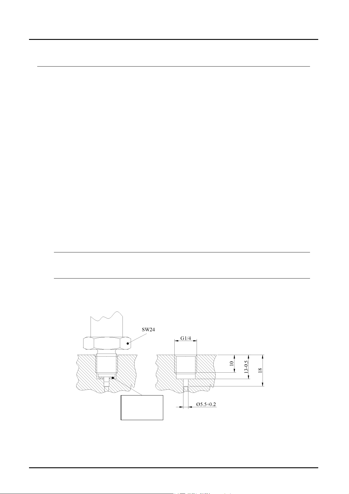
6. Mechanical Connection
Before installation:
• Ensure that the max. pressure in your system is within the prescribed range of
the digital manometer. The measuring range can be read from the nameplate
label of the device.
• Make sure that the permitted max. operational temperature of the device is not
exceeded.
• Confirm that there are no fragments of packing material present inside the
pressure sensing port.
Installation:
• Ensure that the piping is fully depressurised..
• The digital manometer should be mounted just like a mechanical manometer.
• With standard thread connection, sealing is achieved by means of a suitable
gasket (flat-seal or seal-ring DIN 16258).
• While threading in the device, install by using a wrench on the hexagonal
screw (SW 24) and not the gauge housing.
• If possible, after the mechanical installation, pressure test the piping to
determine whether the connection joint is adequately sealed.
Attention! The MAN-SD digital manometer must be installed into a
grounded system. This action is necessary in order to fulfil the EMVguideline.
Flat seal-ring
acc. to
DIN 16 258
MAN-SD 03/04 page 5
Page 6
MAN-SD
7. Electrical Connection
Attention! Please ensure that you use a 9 V – alkali-manganese-block
battery (IEC 6 LR 61).
• Make sure that the power supply lines are not active.
(Only with option limit-contacts or analogue output.)
• Open the battery enclosure on the back-side of the unit and connect the 9V
block battery with the connection plug.
• Place the 9V block battery in the enclosure and close it with the lid.
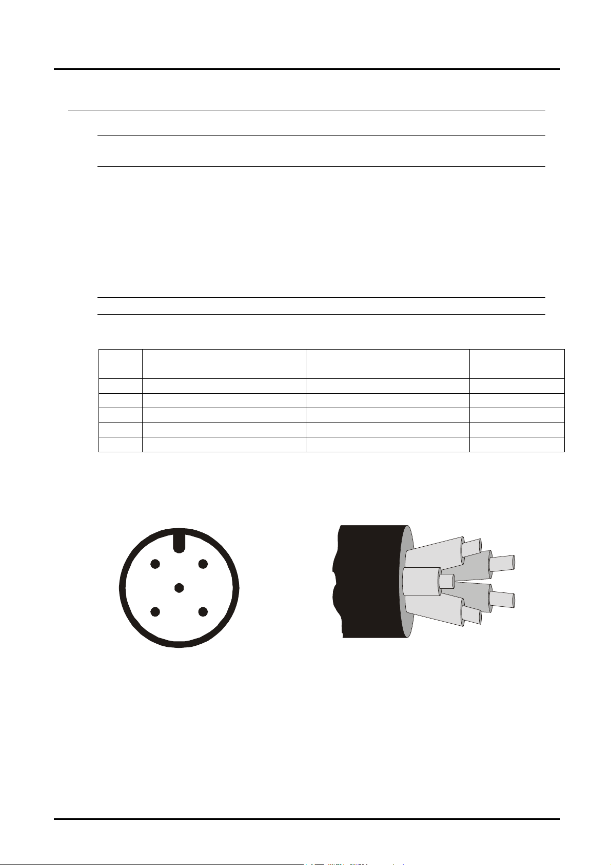
• Terminate the connection wires on the plug (cable), as shown in the illustration
below. (Only with option limit-contacts or analogue output.)
• Power supply conductor (area of cross-section): min.0.34 mm².
Attention! Incorrect wiring will lead to damage of the unit’s electronics.
Cable
No.
1 brown
2 Contact output (Relay in) white
3 GND (0V Reference) blue
4 Analogue output 0-2VDC black
5 Contact output (Relay out) grey
plug M12x1 5-core cable
MAN-SD2... MAN-SD3... Cable colour
21
3
5
View of plug contacts
page 6 MAN-SD 03/04
4
Cable wires colour-coded
Page 7

MAN-SD
8. Function Keys
For the selection of menu options, the following functions keys are available:
È Next Menu Option
Ç Previous Menu Option
P Press once to Switch-on
P Press twice to Switch-off
P & È Exit Menu
Adjustment and Function:
Ç Value-adjustment upwards
È Value-adjustment downwards
P Enter value and jump to next Menu Option
Ç&È Reject input, Return to Menu Option
9. Adjustments
Possible adjustments of the device:
1. Zero point
2. Password (factory pre-set: 0005)
3. Peak value memory (option)
4. Relay and hysteresis (option)
(factory pre-set: switching point on 50% of measuring range)
Factory pre-sets:
1. Battery symbol on: voltage under 7 V
2. Switch-off delay (default: 0 = inactive)
3. Sampling rate/Dampening (default: 5 measurements per second)
4. Analogue output (linear) within measuring range (option)
MAN-SD 03/04 page 7
Page 8

MAN-SD
10. Control Functions
10.1. Standard version MAN-SD10...
and unit with analogue output MAN-SD30...
1xP = Unit Switch on
P
LCD Display
Password input
Automatic zero-point setting
(zero)
Change password
1234
ÏÐ
P A S S
Ï
Z E R O
ÏÐ
P S E t
Ð
Ï
Ï
Ï
P
1xP = Uni t Swi t ch off
P
ÐÏ Ð
&
Canc el
P
Ð
&
Canc el
P
ÐÏ Ð
&
Canc el
0 0 0 0
P
P
4 7 1 1
P
S E t
Password
set on 0005 (fact ory set ti ng)
Access t o further Menu Options
On confirmation, automatic
zero-point adjustment succeeds
Last setting (example)
Password change
Return to Display
page 8 MAN-SD 03/04
Page 9

MAN-SD
10.2. Unit with peak value memory MAN-SD1S...
and unit with peak value memory +
analogue output MAN-SD3S...
1xP = Unit Switched-on
P
LCD-display
Resetting
Peak value memory 1xP = Unit switched-off
Ï
1234
ÏÐ
P
Peak value memory
Password input
Automatic zero-point setting (zero)
Change password
Return to Display
P d u
ÏÐ
P A S S
Ï
Z E R O
ÏÐ
P S E t
Ð
Ï
Ï
Ï
Ï
P
ÐÏ Ð
&
Cancel
P
ÐÏ Ð
&
Cancel
P
Ð
&
Cancel
P
ÐÏ Ð
&
Cancel
o F F
m A x
m I n
o F F
P
0 0 0 0
P
S E t
P
4 7 1 1
P
Last Setting
Register max. value
Register min. value
Peak value memory Off
Select
Confirm selection and goto
next Menu Option
Password
Set on 0005 (Factory setting)
Access to further Menu Options
On confirmation, automatic
zero-point setting succeeds
Last setting (example)
Password change
If the peak value memory is activated, the peak value can be reset by pressing
the left arrow key.
Note: with the switch-off of the device the peak value memory is reset.
MAN-SD 03/04 page 9
Page 10

MAN-SD
10.3. Unit with switching output MAN-SD20...
LCD Display
Password input
Relay set point on rising pressure
Relay set point on falling pressure
Automatic zero-point adjustment (zero)
1234
ÏÐ
P A S S
Ï
r E f
ÏÐ
r E b
ÏÐ
Z E R O
ÏÐ
Ï
Ï
Ï
Ï
P
1xP = Unit Switched-off
P
ÐÏ Ð
&
Cancel
P
ÐÏ Ð
&
Cancel
P
ÐÏ Ð
&
Cancel
P
Ð
&
Cancel
0 0 0 0
P
0 6. 5 0
P
0 6. 4 0
P
S E t
P
Password
Set on 0005 (factory setting)
Access to further Menu Options
Last switching point setting
Set sw. point on 07.50 (example)
Last return switching point setting
Set return sw. point on 06.30
(example)
On confirmation, automatic
zero-point setting succeeds
Change Password
Return to Display
P S E t
P
Ï
Ð
ÐÏ Ð
&
Cancel
4 7 1 1
P
Last setting (example)
Password change
page 10 MAN-SD 03/04
Page 11

MAN-SD
10.4. Unit with switching output + peak value memory
MAN-SD2S...
LDC Displ ay
Resetting
Peak value memory 1xP = Unit Switched-off
Peak value memory
Ï
1234
ÏÐ
P d u
1xP = Unit Switched-on
P
P
P
o F F
m A x
ÏÐ
m I n
o F F
Password input
Relay set point on rising pressure
Ï
P A S S
Ï
Ï
r E f
Ï
ÏÐ
ÐÏ Ð
&
Cancel
P
ÐÏ Ð
&
Cancel
P
ÐÏ Ð
&
Cancel
P
0 0 0 0
P
0 6. 5 0
P
Last setting
Register max. value
Register mi n. value
Peak value memory Off
Select
Confirm sel ection and go to
next Menu Option
Password
Set on 0005 (factory setting)
Access to further Menu Options
Last switching point setting
Set sw. point on 07.50 (example)
Relay set point on falling pressure
Automatic zero-point adjustment (zero)
Change password
Return to Display
r E b
ÏÐ
Z E R O
ÏÐ
P S E t
Ð
Ï
Ï
Ï
P
ÐÏ Ð
&
Cancel
P
Ð
&
P
ÐÏ Ð
&
Cancel
0 6. 4 0
P
S E t
P
4 7 1 1
P
Last return switching point setti ng
Set return sw. point on 06.30 (example)
On confirmation, automatic
zero-point setting succeeds
Last setting (exampl e)
Password change
If the peak value memory is activated, the peak value can be reset by pressing
the left arrow key.
Note: with the switch-off of the device the peak value memory is reset.
MAN-SD 03/04 page 11
Page 12

MAN-SD
11. Maintenance
In case, the medium to be measured is not polluted, the unit is maintenance-free.
12. Technical Information
Nominal size: 74 mm
Accuracy class 0,5 %
Display: 4-digit LCD; digit height 12,7 mm
Measuring range: -1...0, 0...1, 0...1.6, 0...2.5, 0...4, 0...6, 0...10,
Overload range: 3 x P
2 x P
1,5 x PN (from 250 bar)
Power supply: 9 VDC (block battery, IEC 6 LR 01)
Service-life at conversion rate 5/s: 5000 h (block battery 600mAh),
10000 h (Lithium block battery 1200 mAh)
Conversion rate: 5 per sec. (standard)
(1 to 10 per sec. factory-adjustable)
Automatic switch-off times: 2 ...... 90 min, only factory-adjustable
(auto off) (not recommended with analogue or switching
Zero point correction: ≤ ± 25 %
Parts in contact with medium: st. steel 1.4571, ceramic, NBR (Buna-N)
Connection: G ¼ A
(other connection on request)
Medium temperature: -30...+85 °C
Ambient temperature: 0...+60 °C
Storage temperature: -30...+80 °C
Permissible relative humidity: <90%, not condensing
Protection cat.: IP 65
Limit-value relay (Option): N/O, bistable
adjustable setpoint and hysteresis
Max. switching power: 30 V
Analogue output (Option): 0 - 2 V
Load: ≥ 100 kΩ
Electrical connection M 12 x 1 plug DIN (female connector as
accessorie available)
Total cable length: max. 3 metres
Peak value memory (option): MIN or MAX value,
resetting via keypad
0...16, 0...25, 0...40, 0...60, 0...100, 0...160,
0...250, 0...400 bar
(up to 40 bar)
N
(60 to 160 bar)
N
output), 0 = inactive
, 2 A (for relay output)
AC/DC
DC
page 12 MAN-SD 03/04
Page 13

MAN-SD
13. Order Codes
MAN-SD 1 0 C315 0
Output
without..................................................
Relay/N/O contact................................
Analogue output....................................
Peak value memory
without........................................................
with..............................................................
Measuring range code
-1 to 0 bar .......................................................
0 to 1 bar .........................................................
0 to 2.5 bar ......................................................
0 to 4 bar .........................................................
0 to 6 bar .........................................................
0 to 10 bar .......................................................
0 to 16 bar .......................................................
0 to 25 bar .......................................................
0 to 40 bar .......................................................
0 to 60 bar .......................................................
0 to 100 bar .....................................................
0 to 160 bar .....................................................
0 to 250 bar .....................................................
0 to 400 bar .....................................................
Electrical connection
Without...........................................................................
0.5 m cable ...................................................................
Plug M12 x 1 ............................................................
1
2
3
0
S
A315
B025
B045
B055
B065
B075
B085
B095
B105
A115
A125
A135
A145
A155
0
K
S
MAN-SD 03/04 page 13
Page 14

MAN-SD
14. Dimensions
Optional: PG7 (LCD)
4
2
1
x
2
1
M
5114Ø74
0
3
Rotatable
Display
3
5
5
°
9
8
G1/4A
2
SW 24
38
page 14 MAN-SD 03/04
Page 15

MAN-SD
15. Declaration of Conformance
We, Kobold-Messring GmbH, Hofheim-Ts., Federal Republic of Germany,
declare, that the product
Digital Manometer Model: MAN-SD...
complies with the standards given below:
EN 50081-1.2 1994.03
Electromagnetic compatibility - Generic emission standard
EN 61326-1 1998.01
EN 61010-1 1994.03
Safety requirements for electrical measurement, control, and laboratory use
Also, following EWG guidelines are fulfilled:
89/336/EWG
97/23/EG PED
Category I, Table 1, pipe, gas, group 1 dangerous fluids
Signature:
H. Peters M. Wenzel Date: 12.07.02
MAN-SD 03/04 page 15
 Loading...