

Page 1
Operating Instructions
for
Magnetic Level Switches
Model : M Series
Page 2

M series
1. Contents
1. Contents .......................................................................................................... 2
2. Note ................................................................................................................ 3
3. Instrument Inspection ...................................................................................... 3
4. Regulation Use ............................................................................................... 3
5. Float designs ................................................................................................... 4
6. Operating Principle ......................................................................................... 6
7. Mechanical Connection ................................................................................... 6
8. Area of application .......................................................................................... 6
9. Maintenance ................................................................................................... 6
10. Technical Data .............................................................................................. 7
11. Electrical Information..................................................................................... 8
12. Safety Instructions ( ATEX ) ........................................................................ 13
12.1 Area of validity ..................................................................................... 13
12.2 Guidelines. .......................................................................................... 13
12.3 Protection against ESD ( electro static discharges ) ........................... 14
12.4 Chemical resistance ............................................................................ 14
12.5 Maintenance and repairs ..................................................................... 14
12.6 Storage ............................................................................................... 14
13. ATEX Label Description .............................................................................. 14
14. Installation in hazardous zone ..................................................................... 15
15. Electrical connection in ATEX zone ............................................................ 16
15.1 Electrical connection in intrinsically safe mode Ex ia ......................... 16
15.2 Electrical connection in explosion proof mode Ex d ............................ 16
16. Declaration of conformity ATEX Ex ia ......................................................... 17
17. Declaration of conformity ATEX Ex d .......................................................... 18
18. Declaration of conformity ............................................................................ 19
19. ATEX Certified ............................................................................................ 20
20. Notes ........................................................................................................... 30
Manufactured by:
Kobold Mesura S.L.U.
Avda. Conflent 68 nave 15
08915 Badalona
Tel.: +34 93 460 38 83
Fax: +34 93 460 38 76
E-Mail: info.es@kobold.com
Internet: www.kobold.com
Edition: june 2017
page 2 DT0493
Page 3

M series
2. Note
Please read these operating instructions before unpacking and setting the unit
into operation. Follow the instructions precisely as described herein.
The devices are only to be used, maintained and serviced by persons familiar
with these operating instructions and in accordance with local regulations
applying to Health & Safety and prevention of accidents.
When used in machines, the measuring unit should be used only when the
machines fulfil the EC-machine guidelines.
3. Instrument Inspection
Instruments are inspected before shipping and sent out in perfect condition.
Should damage to a device be visible, we recommend a thorough inspection of
the delivery packaging. In case of damage, please inform your parcel service /
forwarding agent immediately, since they are responsible for damages during
transit.
Scope of delivery:
The standard delivery includes:
Magnetic Level Switches for Liquids model: M-...
Operating Instruction
All parts falling under the standard scope of delivery are properly assembled
within the unit.
4. Regulation Use
Magnetic Level Switches are employed for monitoring and control of liquid-levels
in boilers and containers. There are innumerable and diverse applications that
require these Magnetic Level Switches to be made according to customers'
specific requirements.
Attention! These units should not be installed in the vicinity of
strong magnetic fields, since this can impair their intended
functionality.
page 3 DT0493
Page 4

M series
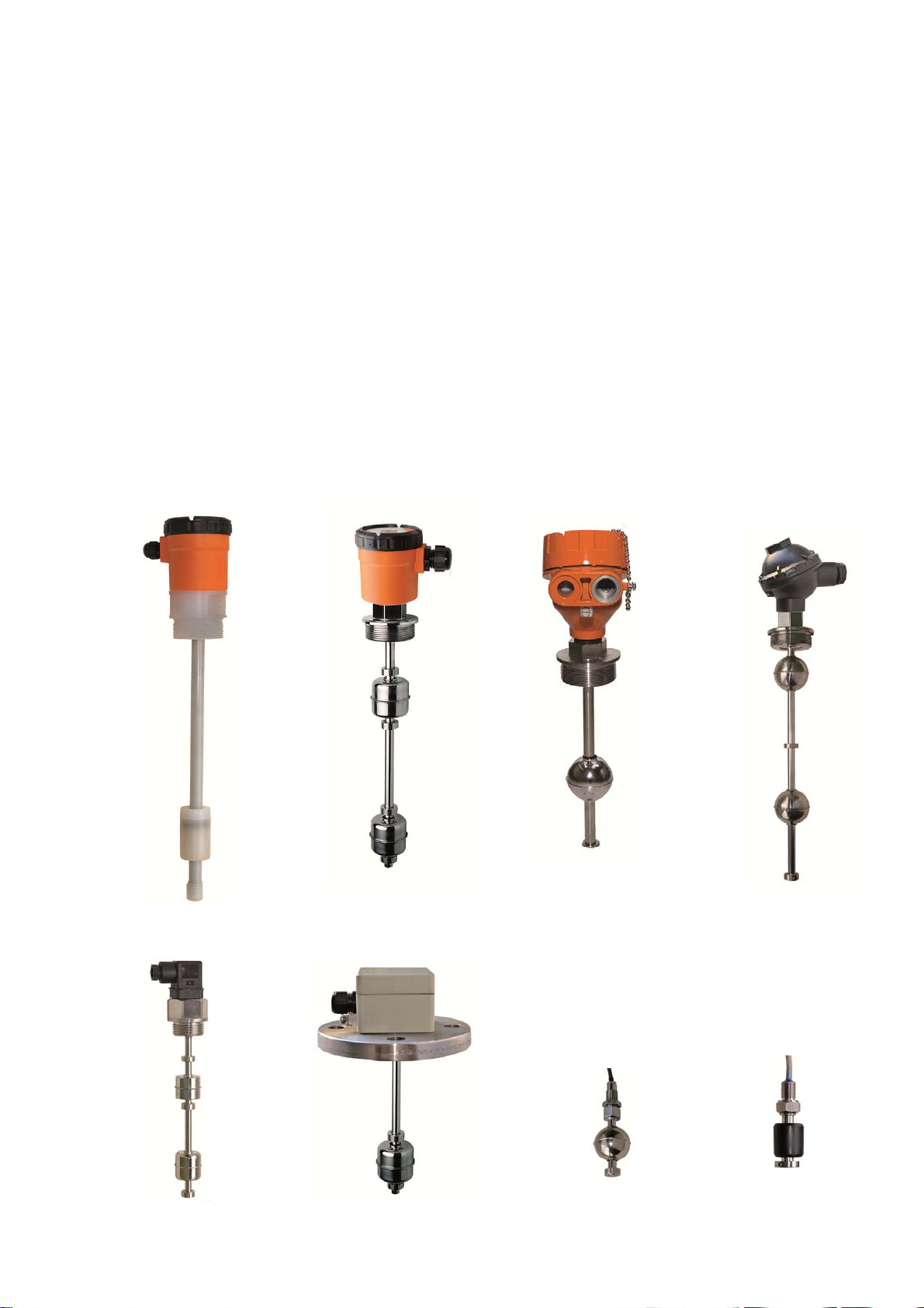
5. Float designs
Float
Model Form Materials
Cylinder
M01
M02
M03
M04
M05
M061)
M07
M08
M10
M11
M13
M16
M20
solid
material
Cylinder
Hollow
Cylinder
hollow
Ball
hollow
Cylinder
hollow
Cylinder
solid
material
Cylinder
hollow
Cylinder
hollow
Ball
hollow
Ball
hollow
Cylinder
hollow
Cylinder
hollow
Ball
hollow
NBR 18 25 10 > 0.6 80 °C 10 bar
PP 26 16 10 > 0.65 80 °C 3 bar
PVC-U 26 26 10 > 0.9 55 °C 3 bar
St. steel
1.4404
PP 42 40 14 > 0.6 80°C 3 bar
PP 40 20 14 > 0.9 90 °C 100 bar
PVC-U 42 40 14 > 0.9 55 °C 3 bar
St. steel
1.4404
St. steel
1.4404
St. steel
1.4404
PVDF 38 60 18 > 0.6 125°C 2 bar
PVC-U 60 60 18 > 0.8 55°C 3 bar
St. steel
1.4404
Outside
[mm]
30 28 9 > 0.8 150 °C 15 bar
44 52 15 > 0.65 150°C 20 bar
52 52 15 > 0.6 150°C 30 bar
52 52 15 > 0.6 150°C 30 bar
95 95 20.8 > 0.5 150°C 15 bar
1) For M06 model. one float is required for each switch point.
For all other floats two contacts can be operated with one float.
Height
[mm]
Hole
Bore
[mm]
Min. Liquid
Density
[kg/dm³]
Max.
Temperature
°C
Nominal
Pressure
[bar] at
20 °C
page 4 DT0493
Page 5

M series
Supplementary devices:
1. Contact protection relays
We recommend the use of contact protection relays in conjunction with sealed
contacts.
Contact protection relays have the following advantages:
No contact overloads arising from sparking and high currents, which can,
for example, be caused by self-induced e.m.f.`s when switching solenoid
valves.
Float switches are electrically isolated from the high voltage power supply
system.
Protection for persons who come into contact with liquids according to
VDE 0100.
Standard models:
Mod. MSR 10 1 channel, 1 changeover
Mod. MSR 20 2 channels, 2 changeover
Mod. MSR 11 2 channels, 1 changeover bistable
Atex models:
Mod. KFD2-SR2-Ex1.W 1 channel, 1 relay output, supply 24 VDC
Mod. KFA6-SR2-Ex1.W 1 channel, 1 relay output, supply 230 VAC
Mod. KFD2-SR2-Ex2.W 2 channel, 2 relay output, supply 24 VDC
Mod. KFA6-SR2-Ex2.W 2 channel, 2 relay output, supply 230 V
2. Damping tube for agitated liquids
Float switches with damping tube for agitated or dirty liquids can be supplied upon
request.
3. Temperature monitoring
Float switches with integrated temperature switch, fixed switch point between
60 °C and 150 °C upon request.
Option: Pt 100 available
4. Mounting instructions
Float switches can also be fitted in the bottom for vessels.
Attention: The contact operation is then reversed.
AC
page 5 DT0493
Page 6

M series
6. Operating Principle
Kobold magnetic float switches are fitted with a hermetically sealed contact which
is situated in the tube.
The float sliding on the tube contains a ring magnet whose magnetic field
switches the sealed contact in a non-contacting fashion. The sealed contacts are
available as N/O, N/C or changeover contacts.
The float sliding up and down on the liquid is the only moving part in the Kobold
magnetic float switches.
7. Mechanical Connection
The slide-tube of the float switch may not be bent or exposed to hard impacts,
since otherwise the reed contacts inside the tube can be damaged.
Adjustment-rings or anchor-clamps may not be readjusted, since otherwise the
switching function (N.O. contact, N.C. contact or changeover switch) is no more
guaranteed.
Ensure the correct use of cable gland and gasket on float switches with plug to
prevent the penetration of humidity.
While installation is carried out, please ensure that the float can move freely (due
allowance should be given to distances from side-walls!).
Mounting position of the slide-tube may not deviate more than ±30° from vertical
position.
If the float has to be removed, pay attention to correct orientation when replacing
the float.
8. Area of application
Magnetic level switch M series are used exclusively for level control and
monitoring of liquid media.
The liquids should not contain suspended solids or tendency to crystallize.
Ensure that the construction materials of the float switch have chemical
resistance sufficient to prevent mechanical deformations that may affect it.
9. Maintenance
In liquids that can cause deposits, the float has to be cleaned at regular intervals.
In this case the measuring tube and float should be cleaned from such deposits.
Other maintenance jobs are not required.
page 6 DT0493
Page 7

M series
10. Technical Data
Contact NO/NC: 230 V
Contact SPDT: 100 V
Contact NO/NC: 230 V
Contact SPDT: 230 V
/ 0,5 A / 10 VA ( M01...M04 )
AC/DC
/ 0,5 A / 3 VA ( M01...M04 )
AC/DC
/ 1 A / 60 VA ( M05...M20 )
AC/DC
/ 1 A / 60 VA ( M05...M20 )
AC/DC
Atex Exia version : Ui: 40V
Protection type: IP64 ( M01...M04 ), IP65 ( M05...M20 )
IP65 ( all models with connection head )
Min. liquid density: See float design table
Max. pressure (at 20ºC): 2 bar ( M13 )
3 bar ( M02, M03, M05, M16 )
3 bar ( M01 with PVC tube )
10 bar ( M01 with st. st. or brass tube )
15 bar ( M04, M20 )
20 bar ( M08 )
30 bar ( M10, M11 )
100 bar ( M06 )
Max. temp. with PVC cable: 55ºC ( models with PVC tube )
70ºC ( Models without PVC tube )
Max. temp. with. silicone cable: See max. temperature in float design table
Max. length of guide tube: 1 m ( PVC Ø8 mm )
2 m ( st. st. or brass Ø8 mm )
2 m ( PVC Ø12 mm )
3 m ( PVDF or PVC Ø16 mm )
4 m ( st. st. or brass Ø12 mm )
6 m ( st. st. Ø18 mm )
Hysteresis: 3-5 mm difference in level
page 7 DT0493
Page 8
M series
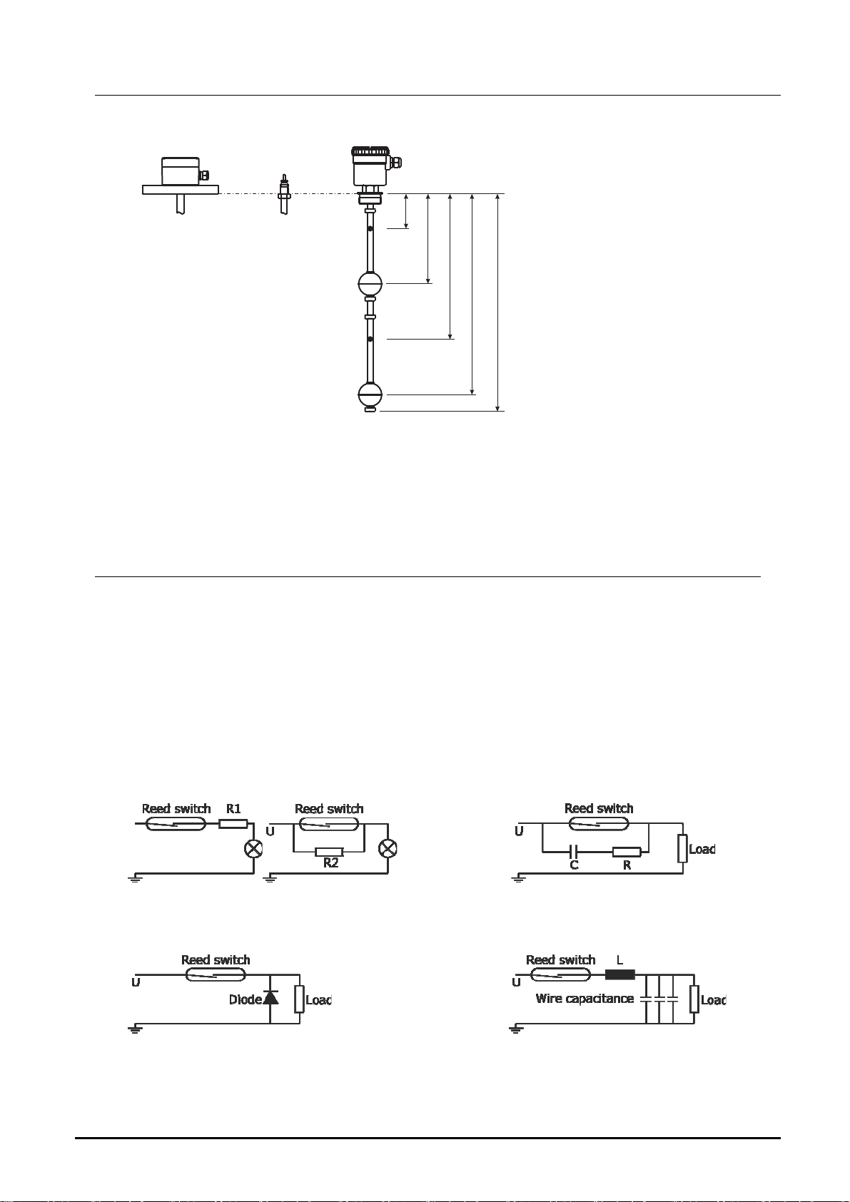
Definition of switching points referred to density 1 Kg/dm
L1
L2
L3
L4
L0
3
Attention models without earth conductor must be used only with safety extra low
voltage ( i.e. contact protection relays ) or external earthing.
11. Electrical Information
Performance data indicated on the device label are absolute maximum ratings,
which may not be exceeded even for brief periods of time. They refer to ohmic
load (resistive load). When switching inductances (e.g. coils from relays and
contactors), the contacts of the float switches should be protected employing
suitable means from high cut-off voltage surges.
Examples of protection circuitry
For capacitive, inductive and lamps load, we recommend our contact protection
relays or the following suppressor circuits.
Lamp load with series or parallel Protection with a RC suppressor
resistance to the reed switch. for a.c. current and inductive load load.
Protection with a diode Protection with an inductance or
for d.c. current and inductive load. resistance for capacitive load.
page 8 DT0493
Page 9
M series
The Magnetic Level Switches are connected according to the following connection
diagrams.
Attention! While making electrical connections of these devices,
please observe relevant safety measures, norms, regulations and ECguidelines, in particular, DIN VDE 0100, section 610. Float switches
made of PVC can be used up to max. 55 °C!
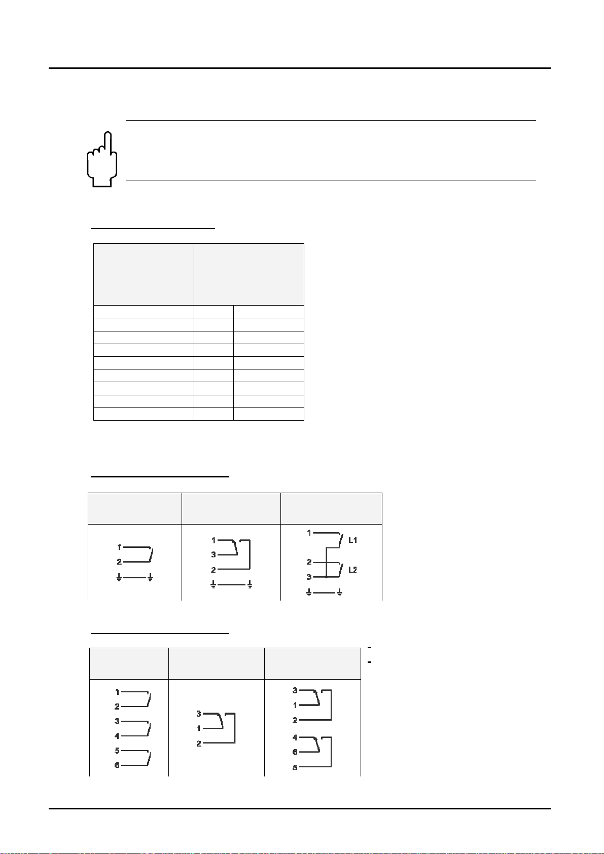
Connection diagrams
Terminal
connection
coding in
connection
head
1 WH White
2 BN Brown
3 GN Green
4 YE Yellow
5 GR Grey
6 PK Pink
7 BU Blue
8 RD Red
9 BK Black
* For special cables the codification is by numbers
Models with Plug 3-pole
L1- S or C L1- W
Models with Plug 6-pole
L1- S or C
L2- S or C
L3- S or C
L1- W
Cable colour
coding
(DIN47100) for
standards in
silicone and PVC
L1- S or C
L2- S or C
L1- W
L2- W
page 9 DT0493
Page 10
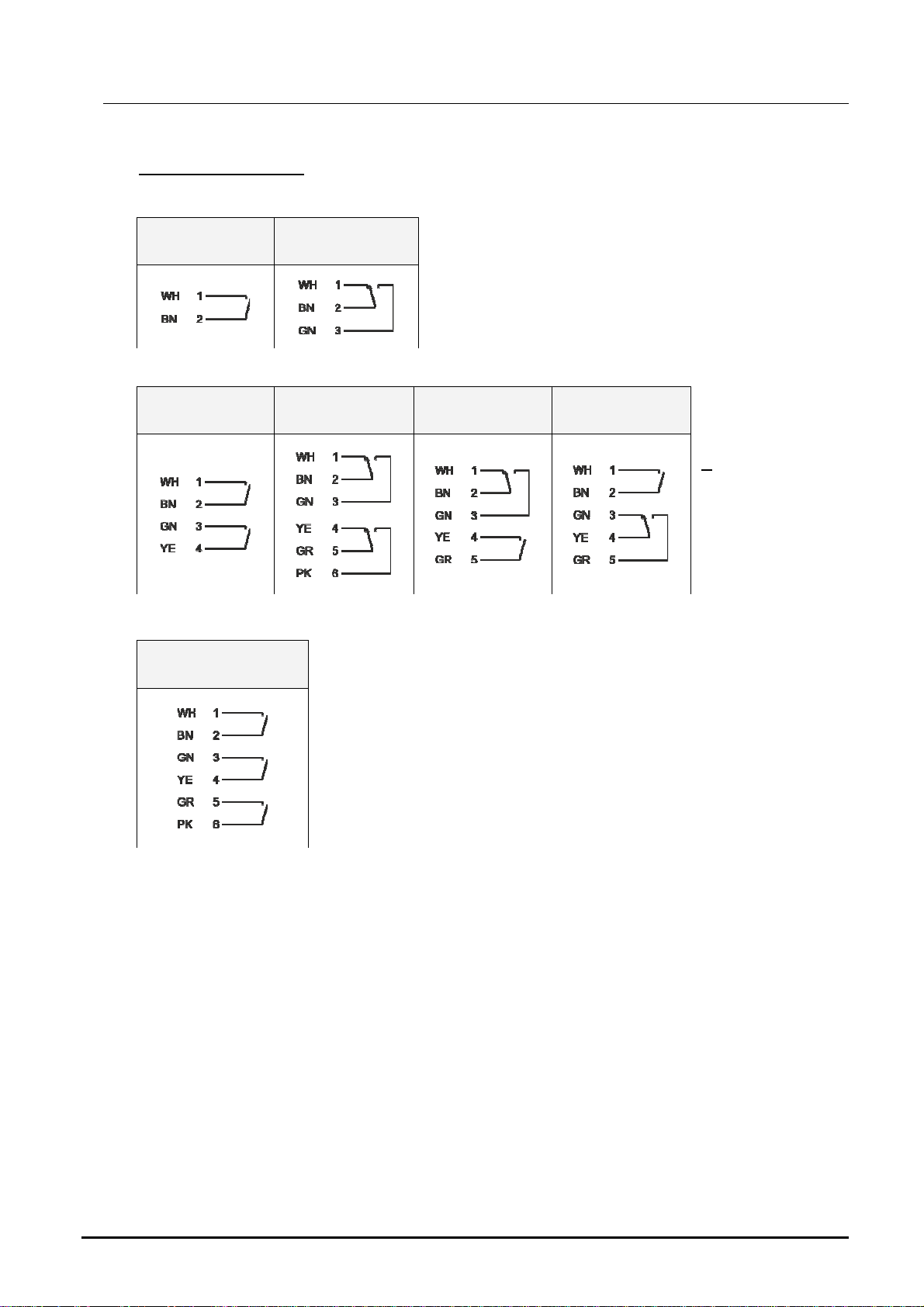
M series
Models M01….M04
1 switch point ( L1 )
L1- S or C L1- W
2 switch points ( L1, L2 )
L1- S or C
L2- S or C
3 switch points ( L1, L2, L3 )
L1- S or C
L2- S or C
L3- S or C
L1- W
L2- W
L1- W
L2- S or C
L1- S or C
L2- W
page 10 DT0493
Page 11

M series
Models M05….M20
1 switch point ( L1 )
L1- S or C L1- W
2 switch points ( L1, L2 )
L1- S or C
L2- S or C
3 switch points ( L1, L2, L3 )
L1- S or C
L2- S or C
L3- S or C
L1- W
L2- W
L1- W
L2- W
L3- W
L1- S or C L2- W L1- W
L1- S or C
L2- S or C
L3- W
L2- S or C
L1- S or C
L2- W
L3- S or C
L1- W
L2- S or C
L3- S or C
L1- W
L1- W
L3- S or C
L1- W
L2- S or C
L3- W
page 11 DT0493
Page 12

M series
4 Switch points ( L1, L2, L3, L4 )
L1- W
L2- S or C
L3- S or C
L4- S or C
L1- S or C
L2- S or C
L3- S or C
L4- S or C
L1- S or C
L2- W
L3- S or C
L4- S or C
L1- S or C
L2- S or C
L3- W
L4- S or C
L1- S or C
L2- S or C
L3- S or C
L4- W
page 12 DT0493
Page 13

M series
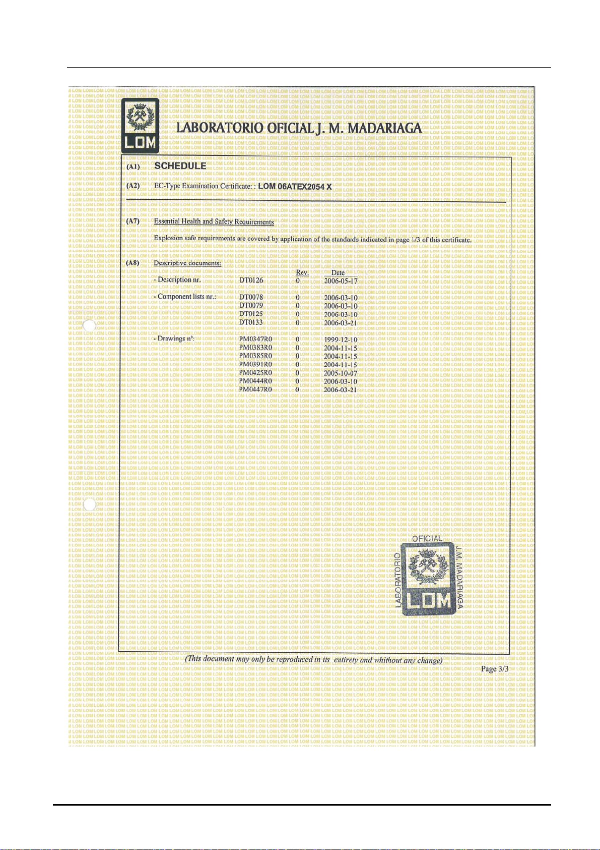
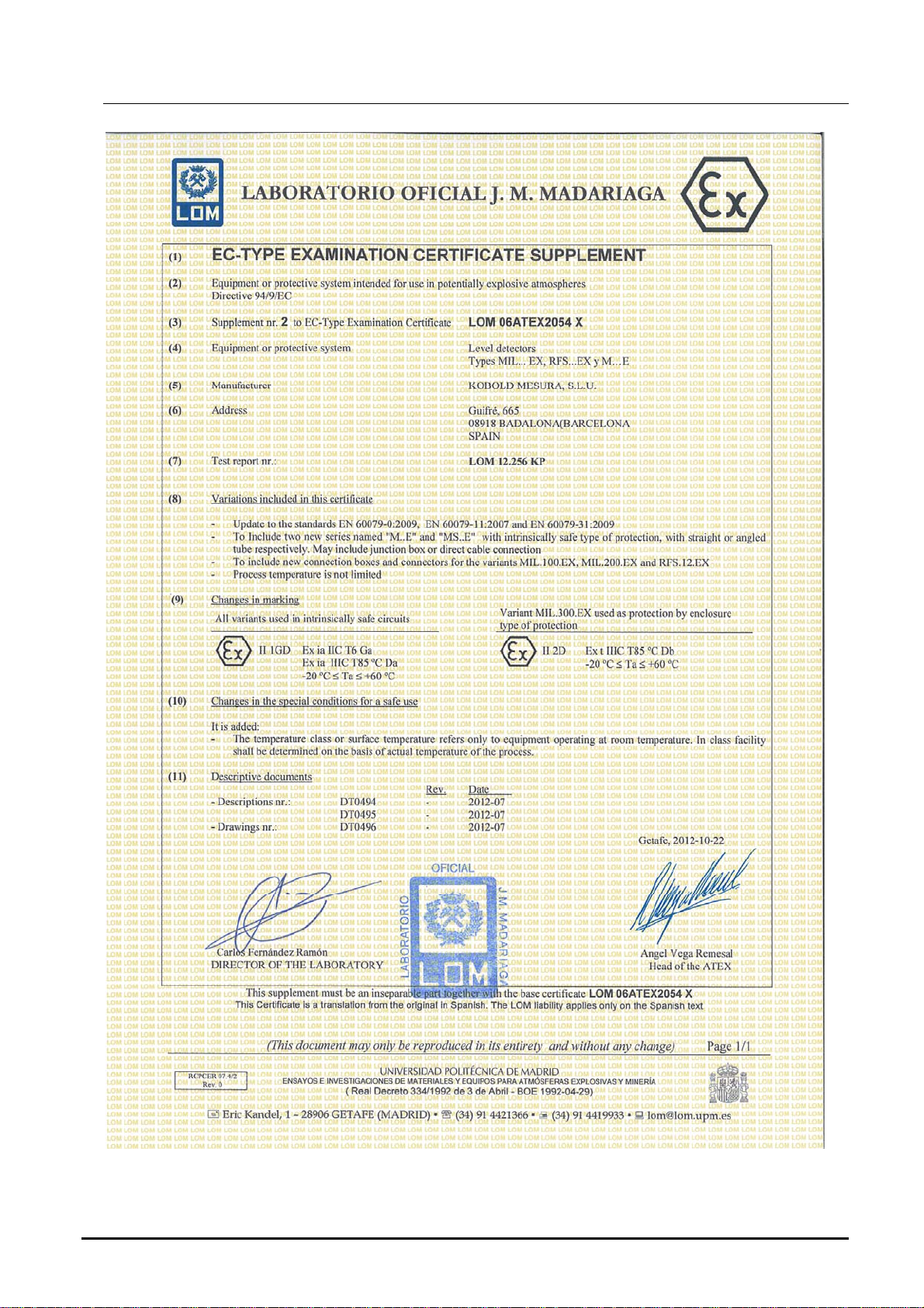
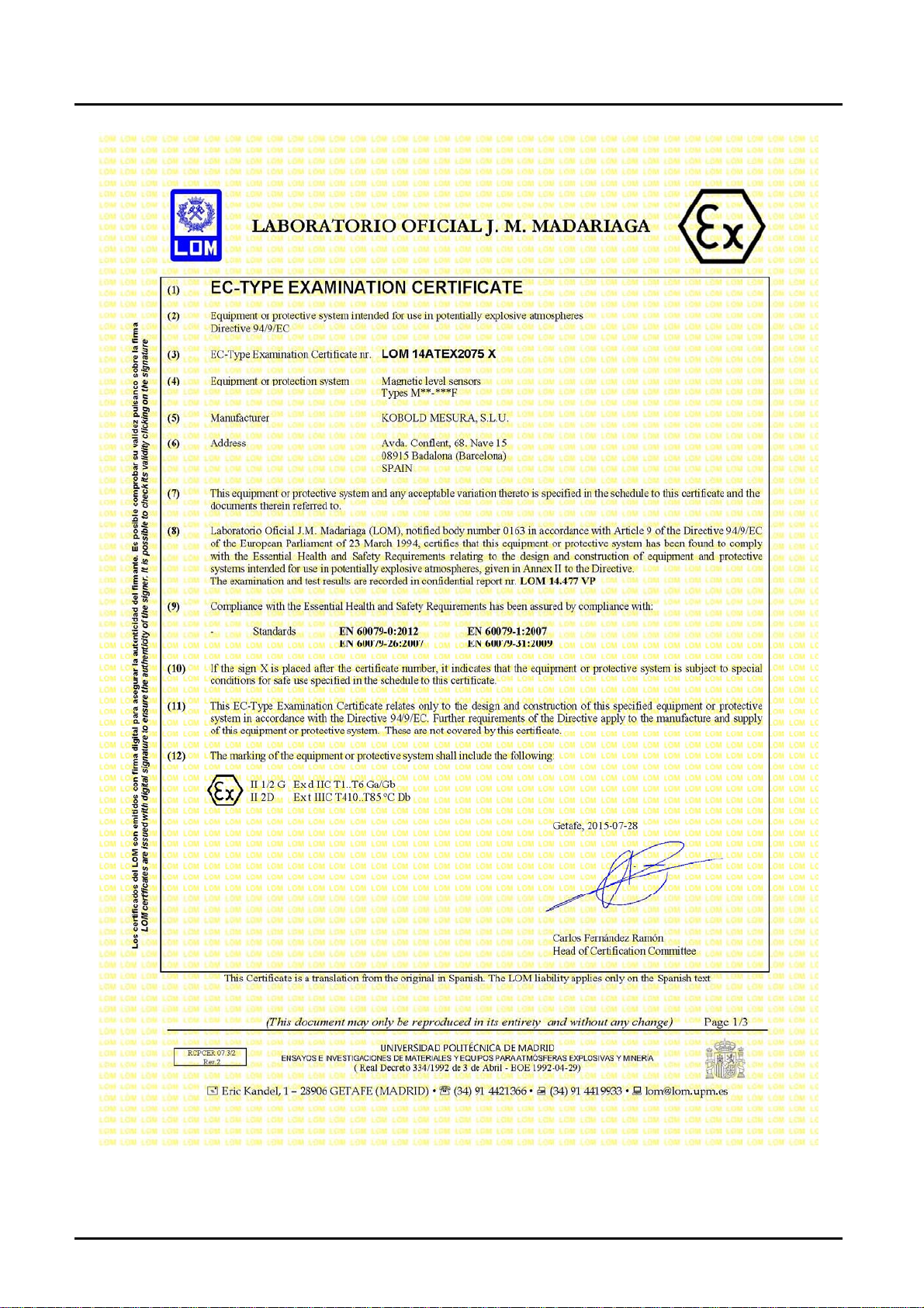
12. Safety Instructions ( ATEX )
12.1 Area of validity
These security instructions apply to M...E series magnetic level switch for use in
explosion-proof atmospheres conform to CE certificate LOM 06ATEX2054 X and
M…F series conforming to CE certificate LOM 14ATEX2075 X
12.2 Guidelines.
These security instructions must be applied to the M...E and M...F series used in
gas or dust explosion hazard environments, category 1G/D.
It is necessary to follow carefully the instructions from the hazardous areas where
the M...E or M...F will be installed, as well as the safety instructions included in this
manual.
Temperature class and/or surface temperature relates solely to a device operated at
ambient temperature. On installation, the actual temperature class for process
operation has to be determined.
The maximum temperature in the enclosure head depends on the process
temperature and may not exceed the maximum service temperature indicated for
the junction box for the instruments M…F series.
The guide tube must be mechanically protected or in locations with low risk of
impact for the instruments M…F series.
When the tank inside is a zone 0, a degree of protection at least IP67 must be
ensured in the process connection for the instruments M…F series.
Inlet bushing and cable glands must conform to the certification for their type in
accordance with the directive.
Models without head box must be protected with an enclosure having at least a
degree of protection IP20 for M...E series.
The use in zone 0 of heads made of aluminium should be restricted to locations
where the risk of ignition due to mechanical impact is not possible.
Verify that all data written in the label of the device matches the data required for the
installation.
Verify that there is no mechanical stress or deformation due to installation in the
tank.
Remove power supply and verify that no explosion risk is present before opening
cover of the housing and check that the cover of housing is correctly mounted before
applying power to the instruments M…F series.
page 13 DT0493
Page 14

M series
The installation of instruments in hazardous areas must be exclusively done by
trained people.
12.3 Protection against ESD ( electro static discharges )
Instruments with plastic parts that can produce electro statics discharges, have a
label for it.
It is important to follow some rules to avoid ESD:
- Avoid rubbing the device.
- Never clean the device dry.
- Do not install the device near material airflows or near steam outlets.
12.4 Chemical resistance
Ensure that the device construction materials have chemical resistance sufficient to
prevent mechanical deformations that may affect the device.
12.5 Maintenance and repairs
The instrument does not require maintenance or servicing.
Repairs must be only carried out by Kobold Mesura ( manufacturer ).
12.6 Storage
Measuring instruments should be protected against humidity and dust.
Storage temperature: -5…+55ºC
13. ATEX Label Description
page 14 DT0493
Page 15

M series
14. Installation in hazardous zone
In classified zones, magnetic level switches series M…E (intrinsically safe version), can
be installed in zone 0, 1 and 2 and series M…F (explosion proof version) can be
installed in zone 0,1 and 2.
Installation must be done by people trained regarding ATEX environments.
Intrinsically safe version Explosion proof version
page 15 DT0493
Page 16

M series
15. Electrical connection in ATEX zone
15.1 Electrical connection in intrinsically safe mode Ex ia
15.2 Electrical connection in explosion proof mode Ex d
page 16 DT0493
Page 17

M series
16. Declaration of conformity ATEX Ex ia
DECLARACIÓN DE CONFORMIDAD EU
EU DECLARATION OF CONFORMITY
EU-KONFORMITÄTSERKLÄRUNG
DÉCLARATION DE CONFORMITÉ EU
DICHIARAZIONE DI CONFORMITÀ EU
KOBOLD MESURA SLU
Avda. Conflent 68 nave 15 08915 Badalona (España)
Declara, bajo la propia responsabilidad, que el producto
Declares under our sole responsibility, that the product
Erklärt in alleiniger Verantwortung, dass das Produkt
Déclare sous sa seule responsabilité, que le produit
Dichiara sotto la propia responsabilità, che il prodotto
Magnetic level switch
M..E
A los cuales se refiere esta declaración, son conformes a las siguiente Directivas Europeas:
To which this declaration relates is in conformity with the following European Directives:
Mit folgenden Euroäischen Richtlinien Konform ist:
À auxquels se réfère cette déclaration, ils sont conformes aux Directives Européennes suivant :
A ai quali si riferisce questa dichiarazione, sono conformi alle direttive europee seguente:
EMC2014/30/EU LVD2014/35/EU ATEX2014/34/EU RoHS2011/65/EU
Normas armonizadas y documentos de la normativa aplicados:
Applied harmonised standards and normative documents:
Angewandte harmonisierte Normen und normative Dokumente:
Normes harmonisées et documents normatifs appliqués
Norme armonizzate e documenti normativi applicati:
EN61010-1 :2011 EN60079-0:2012 (acc. EN60079-0:2013)
EN61000-6-2 :2006 EN60079-11:2012 ( acc. EN60079-11:2013)
EN60079-31:2009 (acc. EN60079-31:2016)
Certificado de examen CE de tipo Marcado
EC-type examination certificate Marking
EG-baumusterprüfbescheinigung Kennzeichnung
Attestation d´examen CE de type Inscription
Certificazione per esame di tipo CE Marcatura
LOM06ATEX2054X
II 1 GD Ex ia IIC T6 Ga / Ex ia IIIC T85ºC Da
-20≤Ta≤+60ºC
Fabricado en: KOBOLD MESURA SLU Avda. Conflent 68 nave 15 08915 BADALONA (Spain)
Made in:
Hergestellt in:
Fabriqué dans:
Fabbricato in:
Organismo notificado
Notified organism Notification number
Zertifizierungsstelle Zertifikatsnummer
Organization annoncée Nombre notification
Organismo informato Notifica di numero
: LOM 0163 Número notificación : LOM 05ATEX9070
Badalona june 2017
DT0497
Gerente
page 17 DT0493
Page 18

M series
17. Declaration of conformity ATEX Ex d
DECLARACIÓN DE CONFORMIDAD EU
EU DECLARATION OF CONFORMITY
EU-KONFORMITÄTSERKLÄRUNG
DÉCLARATION DE CONFORMITÉ EU
DICHIARAZIONE DI CONFORMITÀ EU
KOBOLD MESURA SLU
Avda. Conflent 68 nave 15 08915 Badalona (España)
Declara, bajo la propia responsabilidad, que el producto
Declares under our sole responsibility, that the product
Erklärt in alleiniger Verantwortung, dass das Produkt
Déclare sous sa seule responsabilité, que le produit
Dichiara sotto la propia responsabilità, che il prodotto
Liquid level transducer
M..F
A los cuales se refiere esta declaración, son conformes a las siguiente Directivas Europeas:
To which this declaration relates is in conformity with the following European Directives:
Mit folgenden Euroäischen Richtlinien Konform ist:
À auxquels se réfère cette déclaration, ils sont conformes aux Directives Européennes suivant :
A ai quali si riferisce questa dichiarazione, sono conformi alle direttive europee seguente:
EMC2014/30/EU LVD2014/35EU Atex2014/34/EU RoHS2011/65/EU
Normas armonizadas y documentos de la normativa aplicados:
Applied harmonised standards and normative documents:
Angewandte harmonisierte Normen und normative Dokumente:
Normes harmonisées et documents normatifs appliqués
Norme armonizzate e documenti normativi applicati:
EN61010-1 :2011 EN60079-0:2012 (acc. EN60079-0:2013)
EN61000-6-2 :2006 EN60079-31:2009 (acc. EN60079-31:2016)
EN61326-1:2013 EN60079-1:2007 (acc. EN60079-1:2015)
EN60079-26:2007 (acc. EN60079-26:2015)
Certificado de examen CE de tipo Marcado
EC-type examination certificate Marking
EG-baumusterprüfbescheinigung Kennzeichnung
Attestation d´examen CE de type Inscription
Certificazione per esame di tipo CE Marcatura
LOM 14ATEX2075 X
II 1/2 G Ex d IIC T1..T6 Ga/Gb
II 2 D Ex t IIIC T410..T85ºC Db
Fabricado en: KOBOLD MESURA SLU Avda. Conflent 68 nave 15 08915 BADALONA (Spain)
Made in:
Hergestellt in:
Fabriqué dans:
Fabbricato in:
Organismo notificado
Notified organism Notification number
Zertifizierungsstelle Zertifikatsnummer
Organization annoncée Nombre notification
Organismo informato Notifica di numero
: LOM 0163 Número notificación : LOM 05ATEX9070
Badalona Junio 2017 Gerente
DT0627
page 18 DT0493
Page 19

M series
18. Declaration of conformity
DECLARACIÓN DE CONFORMIDAD EU
EU DECLARATION OF CONFORMITY
EU-KONFORMITÄTSERKLÄRUNG
DÉCLARATION DE CONFORMITÉ EU
DICHIARAZIONE DI CONFORMITÀ EU
KOBOLD MESURA SLU
Avda. Conflent 68 nave 15 08915 Badalona (España)
Declara, bajo la propia responsabilidad, que el producto
Declares under our sole responsibility, that the product
Erklärt in alleiniger Verantwortung, dass das produkt
Déclare sous sa seule responsabilité, que le produit
Dichiara sotto la propia responsabilità, che il prodotto
Magnetic level switch
M…
A los cuales se refiere esta declaración, son conformes a las siguiente Directivas Europeas:
To which this declaration relates is in conformity with the following European Directives:
Mit folgenden Euroäischen Richtlinien Konform ist:
À auxquels se réfère cette déclaration, ils sont conformes aux Directives Européennes suivant :
A ai quali si riferisce questa dichiarazione, sono conformi alle direttive europee seguente:
EMC2014/30/EU LVD2014/35/EU RoHS2011/65/EU
Normas armonizadas y documentos de la normativa aplicados:
Applied harmonised standards and normative documents:
Angewandte harmonisierte Normen und normative Dokumente:
Normes harmonisées et documents normatifs appliqués
Norme armonizzate e documenti normativi applicati:
EN61010-1 :2011
EN61000-6-2 :2006
Fabricado en: KOBOLD MESURA SLU Avda. Conflent 68 nave 15 08915 BADALONA (Spain)
Made in:
Hergestellt in:
Fabriqué dans:
Fabbricato in:
Badalona April 2016 Gerente
DT0498
page 19 DT0493
Page 20

M series
19. ATEX Certified
page 20 DT0493
Page 21

Page 22
M series
page 22 DT0493
Page 23

M series
page 23 DT0493
Page 24
M series
page 24 DT0493
Page 25

M series
page 25 DT0493
Page 26

M series
page 26 DT0493
Page 27
M series
page 27 DT0493
Page 28

M series
page 28 DT0493
Page 29

M series
page 29 DT0493
Page 30

M series
20. Notes
page 30 DT0493
Page 31

M series
page 31 DT0493
Page 32

KOBOLD MESURA S.L.U
Avda. Conflent 68 nave 15
08915 Badalona
Tel.: +34 93 460 38 83
Fax: +34 93 460 38 76
E-Mail: info.es@kobold.com
www.kobold.com
Technical data
Subject to change without prior notice
 Loading...