

Page 1

Manual
Hardware and Software
BA_KMT_e // V5.1 // technical data are subject to change // 193624
Thermal
Mass flow meter
for COMPRESSED AIR and GASES
Model KMT
Page 2

2
We doesn't accept warranty and liability claims neither upon this publication nor in case of improper treatment of the described products.
The document may contain technical inaccuracies and typographical
errors. The content will be revised on a regular basis. These changes
will be implemented in later versions. The described products can be
improved and changed at any time without prior notice.
© Copyright
All rights reserved.
USA
FCC notice:
This equipment has been tested and found to comply with the limits for a Class B
digital device, pursuant to part 15 of the FCC Rules. These limits are designed to
provide reasonable protection against harmful interference in a residential installation. This equipment generates, uses and can radiate radio frequency energy and,
if not installed and used in accordance with the installation manual, may cause
harmful interference to radio communications. However, there is no guarantee that
interference will not occur in a particular installation. If this equipment does cause
harmful interference to radio or television reception, which can be determined by
turning the equipment off and on, the user is encouraged to try to correct the
interference by one or more of the following measures:
- Reorient or relocate the receiving antenna.
- Increase the separation between the equipment and receiver.
- Connect the equipment into an outlet on a circuit different from that to which the
receiver is connected.
- Consult the dealer or an experienced radio/TV technician for help.
Caution:
Any changes or modifications not expressly approved by the party responsible for
compliance could void the user's authority to operate this device.
CANADIAN
ICES-003 notification:
This Device B digital apparatus complies with Canadian ICES-003.
Cet appareil numérique de la classe B est conforme à la norme NMB-003 du
Canada.
Page 3

3
1. GENERAL
............................................................................................................ 4
1.1. Symbol Clarification ................................................................................................. 4
1.2. Safety Instructions .................................................................................................. 4
1.2.1. Intended Use ................................................................................................... 4
1.2.2. Installation, start up and control
.................................................................................. 5
1.3. Environmental aspects .............................................................................................. 5
2. PRODUCT DESCRIPTION ....................................................................................... 6
3. INSTALLATION ...................................................................................................... 7
3.1. Mounting dimensions ............................................................................................... 7
3.1.1. KMT-1, KMT-2 and KMT-3 ....................................................................................... 7
3.1.2. KMT-4
......................................................................................................... 8
3.2. Determining installation site .........................................................................................8
3.2.1. Process pressure ............................................................................................... 8
3.3. Installation position .................................................................................................. 9
3.4. Required length of straight pipe.....................................................................................10
3.5. Installation KMT-1, KMT-2 and KMT-3 .............................................................................. 11
3.5.1. Measurement ball valve ......................................................................................... 11
3.5.2. Assembly without flow meter, but with screw cap instead (blind cap)
................................................ 11
3.5.3. Shut off the measurement ball valve
.............................................................................. 11
3.5.4. Installation of the flow meter sensing probe
....................................................................... 12
3.5.5. Removal of the sensing probe of the flow meter
................................................................... 12
3.6. Installation KMT-4 in the pipe line .................................................................................. 13
3.7. Setting the pipe diameter ...........................................................................................15
4. ELECTRICAL CONNECTIONS ................................................................................. 16
4.1. Connection diagram ................................................................................................. 16
4.1.1. Relay and pulse output, internal switching ........................................................................ 16
5. CONTROL COMPONENTS ...................................................................................... 17
5.1. Jumper for Output ................................................................................................... 17
5.2. Digital interface USB ( for configuration)............................................................................17
5.3. Display / Indicator with keypad (optional) ........................................................................... 18
5.3.1. Indication of the analogue and pulse output ....................................................................... 18
5.3.2. Indication of the switch output
.................................................................................... 18
5.3.3. Indication of the MIN / MAX values
............................................................................... 19
5.3.4. Reset of the consumption counter or the MIN / MAX value
......................................................... 19
5.3.5. Maximum consumption counter
.................................................................................. 19
6. ERROR MESSAGES .............................................................................................. 20
7. MAINTENANCE ..................................................................................................... 20
7.1. Cleaning of the sensor of the flow meter ...........................................................................20
8. REPLACEMENT PARTS / ACCESSORIES ................................................................. 20
8.1. Order Code Replacement Sensor ..................................................................................20
8.2. Order Code Replacement sensor cable ............................................................................21
8.3. Order Code Accessories for KMT-4 ................................................................................. 21
9. TECHNICAL DATA KMT-1, KMT-2 and KMT-3 ............................................................ 22
10. TECHNICAL DATA KMT-4 ...................................................................................... 24
Table of contents - HARDWARE
Table of contents - SOFTWARE
1. General ................................................................................................................ 26
2. Installation ........................................................................................................... 26
2.1. Configuration of the USB Interface (VirtualCOM) ................................................................... 27
3. User Interface ....................................................................................................... 28
4. Menu toolbar ........................................................................................................ 28
4.1. File .................................................................................................................. 28
4.2. Transmitter .......................................................................................................... 29
4.3. Extras ............................................................................................................... 29
5. Input Screen ......................................................................................................... 29
5.1. Output 1, Output 2 ..................................................................................................29
5.1.1. Output mode ................................................................................................... 29
5.1.2. Measurand
..................................................................................................... 29
5.1.3. Units
........................................................................................................... 29
5.1.4. Output mode – analogue
........................................................................................ 29
5.1.5. Output mode – switch (relay)
.................................................................................... 30
5.1.6. Output mode – pulse
............................................................................................ 31
5.2. Minimum flow shutdown ............................................................................................31
5.3. Display .............................................................................................................. 31
5.4. Adjustment .......................................................................................................... 32
5.4.1. 1-point adjustment .............................................................................................. 32
5.4.2. 2-point adjustment
.............................................................................................. 33
5.4.3. Reset to factory settings
......................................................................................... 33
5.5. Measuring values overview ......................................................................................... 34
5.5.1. Reset of the MIN / MAX values .................................................................................. 34
5.5.2. Reset of the consumption counter (totalizer)
....................................................................... 34
5.6. Setting up Process Parameters ..................................................................................... 34
5.6.1. Change the Process Gas ........................................................................................ 34
5.6.2. Changing the standard conditions
................................................................................ 35
5.6.3. Pressure compensation
......................................................................................... 35
5.6.4. Setting the pipe diameter
........................................................................................ 35
5.7. External pressure transmitter for pressure compensation .......................................................... 35
5.8. Declaration of Conformance ........................................................................................35
Page 4

4
1. GENERAL
This manual is a part of the scope of supply and serves to ensure optimal operation and functioning of the
equipment.
For this reason, the manual must be read before start-up.
Therefore, it is necessary that this manual is read and understood by those responsible for the handling,
installation, and maintenance of the equipment.
This manual may not be used for competitive purposes or passed on to third parties
without the written consent.
It is permitted to make copies for personal use.
All information, technical data and illustrations contained in these instructions are based on
information available at the time of publication.
1.1. Symbol Clarification
This symbol indicates safety instructions.
The safety instructions have to be carried out unconditionally. If disregarded loss, injury, or damage may be
inflicted to people and property. In any case we cannot be hold responsible.
This symbol indicates attention.
The note should be observed to achieve an optimal functioning of the equipment.
1.2. Safety Instructions
1.2.1. Intended Use
The flow meter is intended to be used for the measurement of air and other non-corrosive gases in pipelines
only. Consult the factory first before the measurement of wet or filthy gases.
The design of the flow meter allows for the KMT to be installed in a pressurized system up to PN16 – is
16 bar (230 psi).
For KMT-1, KMT-2 and KMT-3:
Prior to the start of the installation, the system has to be depressurized. Before the installation or
removal of the sensing probe or the screw cap, the measurement ball valve should be closed.
Mounting, electrical installation, putting in operation and maintenance should only be done by qualified
personnel.
The use of the flow meter in any other way than described in this manual bears a safety risk for people and
the entire measurement installation and is therefore not allowed.
The manufacturer cannot be hold responsible for damages as a result of incorrect handling, installation, and
maintenance of the equipment.
To avoid health risks or damage to the equipment, the installation should not be operated on with tools, which
are not specifically mentioned or described in this manual.
Excessive mechanical stress and inappropriate handling must be avoided.
For KMT-1, KMT-2 and KMT-3:
A short interruption of the flow using the measurement ball valve cannot be avoided when exchanging the
sensing probe.
The flow meter can only be utilized in accordance with the conditions defined in the technical data. Otherwise,
inaccuracies of the measurement will occur and equipment failures cannot be ruled out.
For the safety of the user and for the functionality of the equipment the recommended steps by the
manufacturer to put into operation, to test and to maintain should be taken and completed.
Page 5

5
1.2.2. Installation, start up and control
The flow meter is designed and built in accordance with the latest state in technology, tested adequately and
has been shipped from the factory in good order and condition.
As the user, you are responsible to comply with all applicable safety regulations amongst others:
• Instruction for the installation
• Local standards and codes
The manufacturer has taken all measures to assure safe operation. The user has to make sure that the
equipment is positioned and installed in such a way that safe operation is not impaired.
The equipment is tested in the factory and shipped in good order and condition.
This manual contains information and notes of caution, which have to be adhered to by the user to assure a
safe operation.
• Mounting, electrical installation, putting into operation and maintenance should only be done by
qualified personnel. The plant operator should authorize qualified personnel to operate on the
installation.
• It is necessary that this manual is read and understood by these professionals and that they follow
the instructions as detailed in this manual.
• Check all connections of the entire installation thoroughly, before putting the system into operation.
• Disconnect the device from power supply before opening or closing to avoid damages.
• Do not put a damaged product into operation and make sure that that does not happen inadvert-
ently.
• A malfunction of the equipment should only be handled and fixed by authorized and qualified
personnel.
• If it is not possible to repair the malfunction, put the equipment out of operation and make sure that
it cannot be put back into operation again.
• Repairs not described in this manual may only be carried out by the manufacturer or by the
respective service organization.
Disclaimer of Liability
The manufacturer or their delegated representative is only liable in case of intend or gross negligence. The
accountability is limited to the value of the order issued at the time to the manufacturer.
The manufacturer is not liable for damages, originated from disregarding the safety instructions or violating
the instructions of the manual or operating conditions.
Consequential damages are excluded from the any liability.
1.3. Environmental aspects
The products are developed and designed in due consideration to the importance of the protection of the
environment. Therefore, disposal of the product also should not lead to pollution of the
environment.
The single-variety components must be separated before the transmitter is disposed of. The electronic
components must be collected and as electronic scrap properly be disposed of.
Page 6
6
2. PRODUCT DESCRIPTION
The flow meter of the series KMT, based on the measurement principle of thermal mass flow, is suited for the
measurement of flow of air and gases in pipelines. Measurement of for instance the consumption of compressed air, nitrogen, CO2, oxygen or other non-corrosive and non-flammable gases.
The KMT measures the volume flow at standard conditions according to DIN 1343 (P0 = 1023.25 mbar;
t0 = 273.15 K or 0 °C (32 °F). In addition to the standard volume flow, the measurand mass flow, norm flow
and temperature are available.
The KMT has an integrated consumption counter. The consumption quantity is indicated in the display and is
not lost after a power failure. Two signal outputs are available. Depending on the application, the outputs can
be configured as analogue (current or voltage), switch output or as pulse output for the measurement of the
consumption.
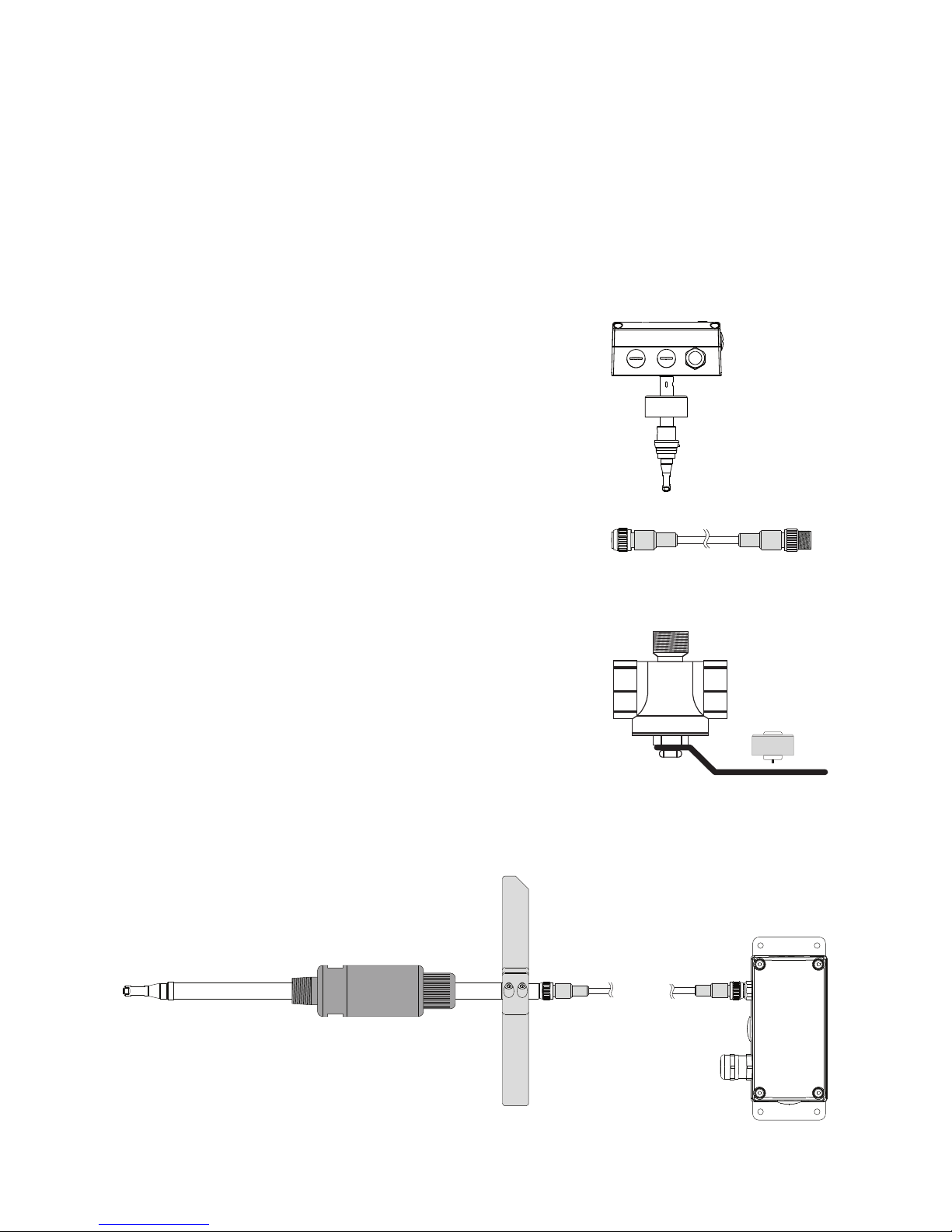
Measurement ball valve
The measurement ball valve allows for the easy and reliable installation within the pipeline. During installation in the pipeline, observe the
required inlet and outlet paths (see page 10). The nominal size of
the measurement ball valve must match the nominal size of the pipe.
The measurement valve with shut-off function allows for the instalment and removal of the sensing probe with only interrupting the
process flow for a short moment. The measurment ball valve is suitable for pressures up to 16 bar (PN16) and available for pipe
diameters DN15 (1/2”) to DN50 (2”).
Signal conditioning with optional display
The enclosure with the signal conditioning is mounted either on the
measurement probe (model 1 or 2 compact) or is remote with a pluggable sensor cable up to 10 meter (33 feet) – (model 3 with remote
probe).
Sensing probe with measurement electronics
The interchangeable sensing probe contains the sensor element and
the measurement electronics, in which the data of the factory calibration is stored. The sensing probe is easy and quickly interchangeable
intheeld,independentoftheelectronicsforthesignalconditioning.
Aftertheexchange,thecongurationoftheoutputsisunchanged.
Screw cap
The screw cap, with female thread, is screwed in place if the flow
meter is not installed and the pipeline has to be used.
Sensor cable (only by model 3 with remote sensing probe)
The sensor cable allows for the remote installation, up to 10 meter
(33 feet), of the sensing probe from the housing with the signal
conditioning.
1
5
3
4
2
1
2
3
5
4
KMT-1, KMT-2 and KMT-3
KMT-4
1
2
36
7
Page 7
7
3. INSTALLATION
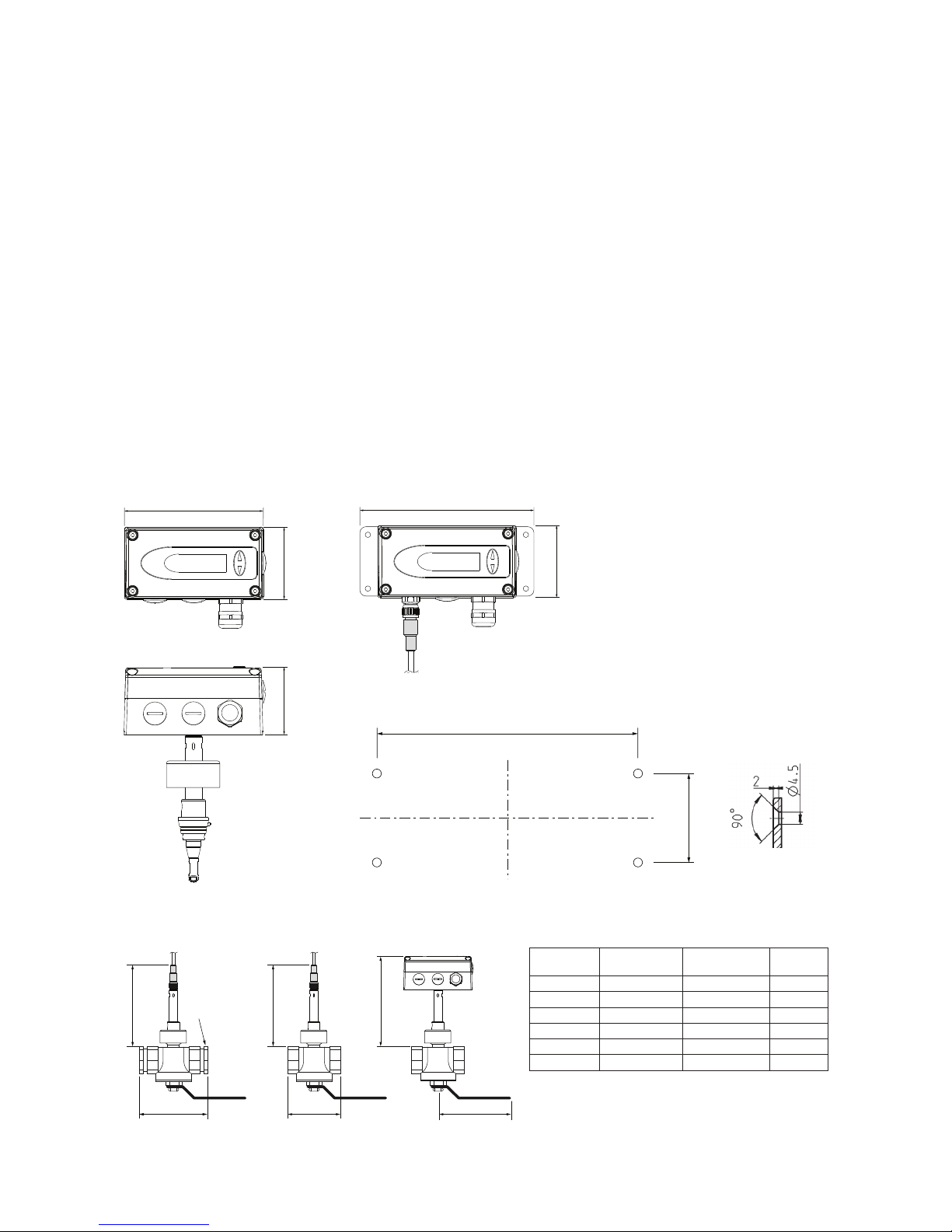
3.1. Mounting dimensions
3.1.1. KMT-1, KMT-2 and KMT-3
115
145
129
60
56
60
40
cable gland
M16x1.5
cable gland
M16x1.5
Cross-section
bore hole:
Drilling Plan:
The bottom part of the housing is mounted with
4 screws (not in the scope of supply)
Max. screw diameter: 4.5 mm (0.17 inch).
e.g. 4.2 x 38 mm DIN 7938H Screws
Measurement ball valve
Non-return protection for secure mounting
The patented non-return protection combines three functions in one device:
• Non-return protection
The sensor can only be pushed in one direction during installation. The sensor cannot return at all,
even if it is released.
• Seal
By means of an encapsulated O-ring, no compressed air can escape under pressure during assembly.
• Precise positioning
The precise positioning with respect to immersion depth and orientation is easy to perform, guaranteeing accurate measurement results.
Mounting grip
With the mounting grip, the sensing probe is inserted and correctly positioned into the pipe line.
7
6
183 (7.2)
173 (6.81)
A A B
Only at DN15:
Reduction
3/4“-1/2“
173 (6.81)
Measurment
ball valve
Thread A B
DN15 R
p
1/2" 100±8 (3.94±0.32) 92 (3.62)
DN20 Rp or NPT 3/4” 72 (2.83) 92 (3.62)
DN25 Rp or NPT 1” 83 (3.27) 124 (4.88)
DN32 Rp1 1/4" 100 (3.94) 124 (4.88)
DN40 Rp or NPT 1 1/2" 110 (4.33) 147 (5.79)
DN50 Rp or NPT 2” 131 (5.16) 147 (5.79)
dimensions in mm (inch)
Female thread: BSP thread acc. EN 10226 (old DIN 2999) or NPT
Page 8
8
3.2. Determining installation site
•
The installation site should be easy accessible and free of vibrations and shocks
• Observe enough clearance above the mounting position, in order to be able to install and remove
the sensing probe:
at least 120 mm (4.72) for KMT-1, KMT-2 and KMT-3
at least 450 mm (17.7”) for KMT-4 probe length 165 mm (6.5”) DN65 (2 1/2”) up to DN100 (4”)
at least 600 mm (23.6”) for KMT-4 probe length 315 mm (12.4”) DN125 (5”) up to DN300 (12”)
at least 750 mm (30.0”) for KMT-4 probe length 465 mm (18.3”) DN305 (14”) up to DN700 (28”)
• The ambient temperature should not exceed the value as stated in the specifications
(see page 22) – consider heating by radiation.
• The fluid should not condense at the installation site. Condensation on the tip of the sensing probe
must be avoided.
• In compressed air systems, the installation should be downstream of the dryer.
• Observe the direction of the flow by the installation (see page 11).
• Observe the required straight pipe lengths up and downstream, in order to warrant the specified
measurement accuracy.
• The flow meter should be installed as far as possible from any flow disturbance. Valves or check-
valves should be installed in a respective distance from the flow meter.
3.2.1. Process pressure
Because of the measuring principle the thermal mass flow meter KMT is largely independent of the process
pressure and is factory calibrated at a pressure of 7 bar (100 psi) (KMT-1, KMT-2 and KMT-3) or 9 bar (130.5
psi) (KMT-4).
In order to achieve the highest measurement accuracy, the slight dependence on process pressure can be
compensated for in two ways:
• if the process pressure is stable, by programming the pressure value in the configuration software
(see page 35).
• in case of strong fluctuations of the process pressure (e.g. 3 to 10 bar (40 to 150 psi)) an external
pressure transmitter can be installed and connected to the pressure-compensation input
(see page 35).
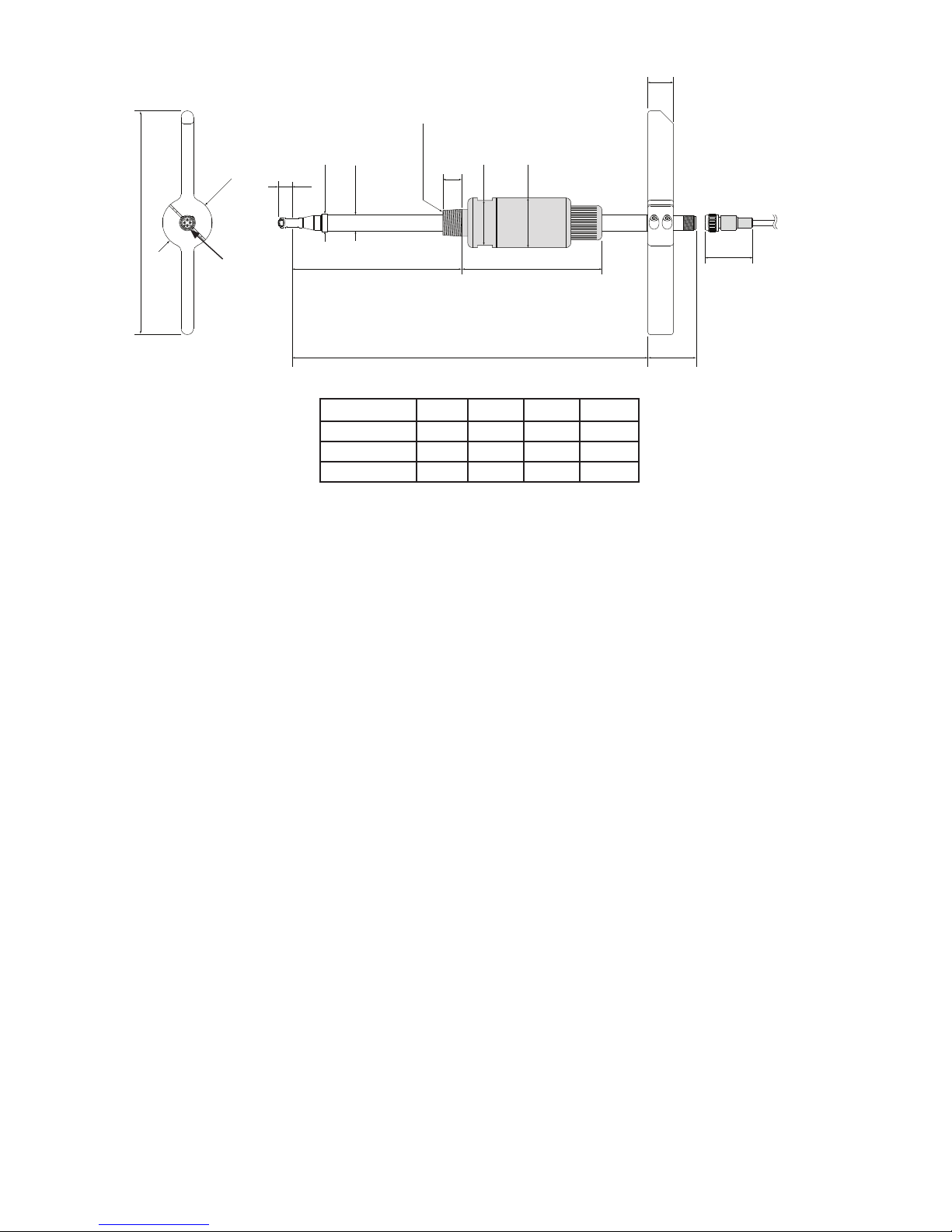
R 1/2“ thread
M12x1 Connector
for probe cable
B
variable insertion depth
max. A
45
(1.77“)
38 (1.5“)
20 (0.79“)
15
(0.59“)
12
(0.47“)
120 (4.72“)
180 (7.09“)
Ø 40 (1.57“)
Ø 13 (0.51“)
Ø 14 (0.55“)
Ø 40 (1.57“)
SW 36 (1.42“)
see accessories for NPT adapter
3.1.2. KMT-4
Pipe Ø
A [mm] B [mm] A [inch] B [inch]
DN50...DN100 165 285 6.5 11.22
DN125...DN300 315 435 12.4 17.13
DN350...DN700 465 585 18.3 23.03
Page 9
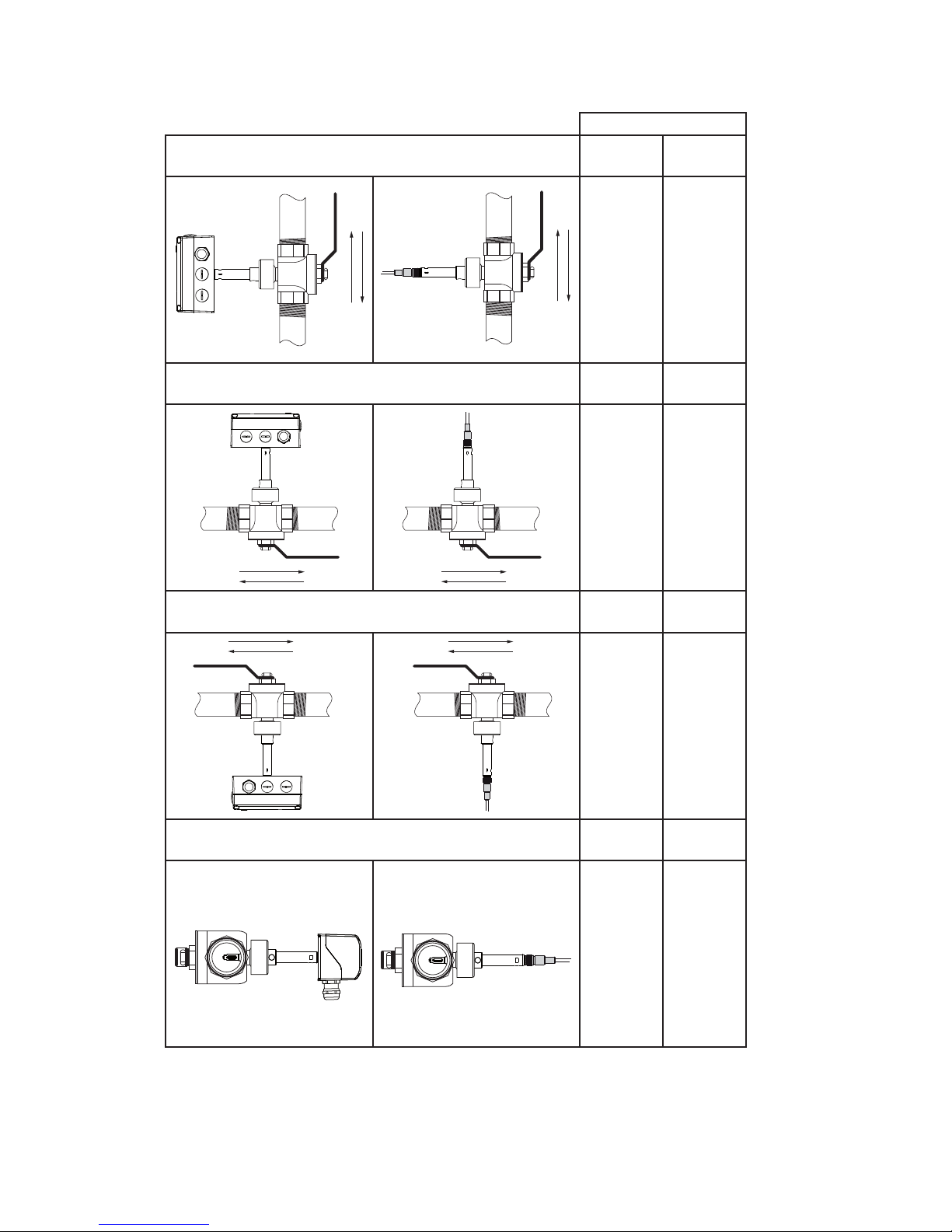
9
Model
Vertical Mounting Compact Remote
+ ++
Horizontal Mounting, sensor upwards
++ ++
Horizontal Mounting, sensor downwards
- -
Horizontal Mounting, sensor across
+ ++
3.3. Installation position
Make sure that the arrow on the tip of the sensing probe is pointing in the direction of the flow.
++ ... recommended installation position
+ ..... not recommended if there is vibration on the pipeline
-....... not recommended
Page 10
10
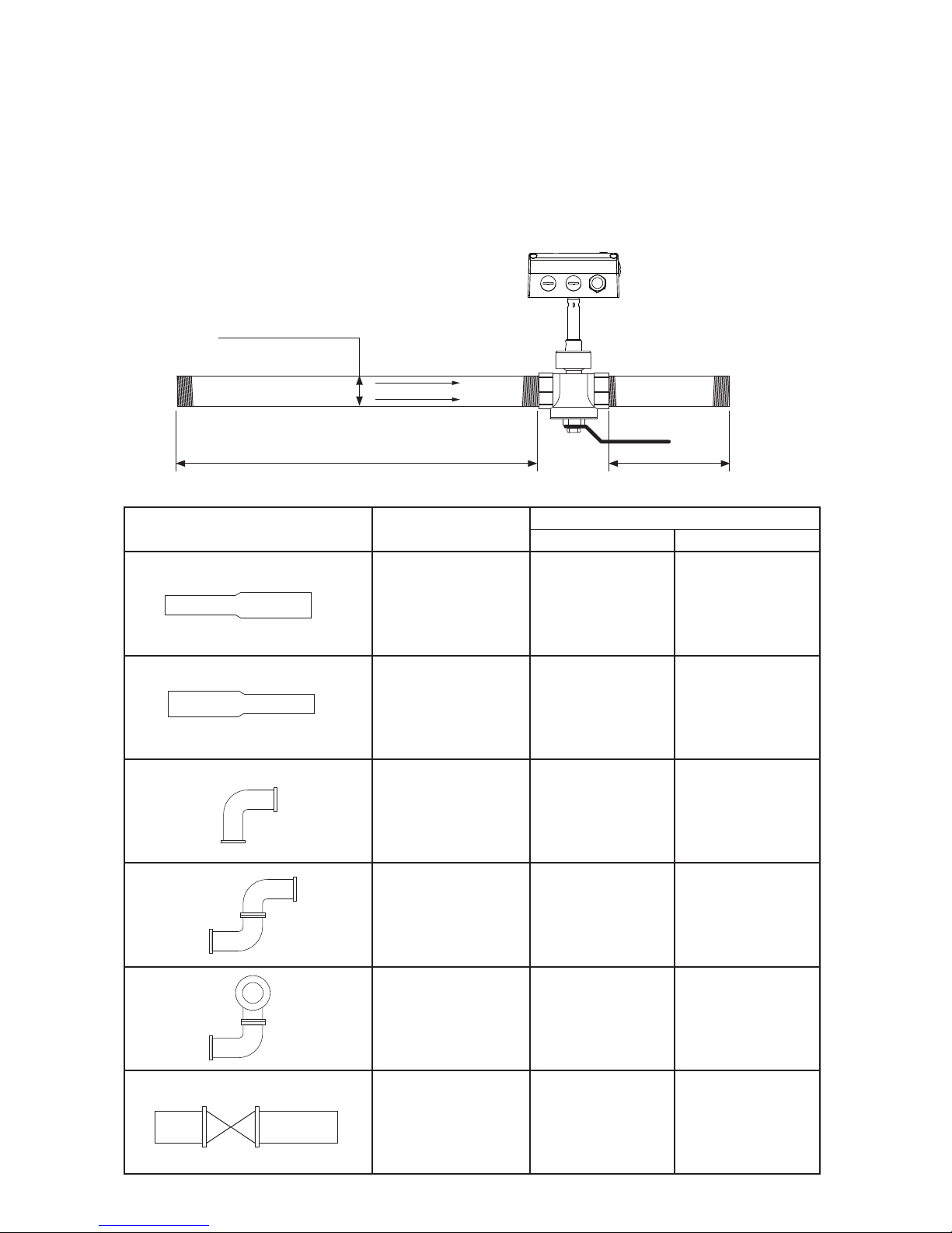
Type
(DN = Nominal Pipe Size)
Straight inlet pipe Straight outlet pipe
Extension 15 x DN 5 x DN
Reduction 15 x DN 5 x DN
90° - elbow 20 x DN 5 x DN
Two 90° - elbows,
in one level
25 x DN 5 x DN
Two 90° - elbows,
in two levels
30 x DN 5 x DN
Valve, gate valve 50 x DN 5 x DN
3.4. Required length of straight pipe
The flow meter should be installed as far as possible from disturbances of the flow. The causes for disturbance
of the flow are for instance, reducers, elbows, T-pieces, valves, gate valves, etc. The specified measurement
accuracy can be achieved only when the following straight inlet and outlet pipe lengths are installed:
• The stated values are as a minimum. If possible, allow for greater distances.
• Valves or gate valves should be installed downstream of the flow meter.
• With lighter gases the inlet straight pipe should be longer.
• Only for KMT-1, KMT-2 and KMT-3: The wall thickness of the inlet and outlet pipe should be 2,6 mm
owdirection
straight inlet pipe
nominal pipe size (DN)
straight outlet pipe
Page 11
11
3.5. Installation KMT-1, KMT-2 and KMT-3
3.5.1. Measurement ball valve
• all connections to be made with appropriated sealing material on the threads.
• the sealing material should not change the area of the inner cross section of the pipe. It must be
warranted that the connections after installation are free of leaks.
• All fittings must be tested on seal tightness.
• Observe the required length of inlet and outlet pipe section.
• The recess for the alignment pin must be at the side of the outlet.
recess for
alignment pin
Flow Direction
3.5.2. Assembly without flow meter, but with screw cap instead (blind cap)
In order to use the measurement section without the flow meter, the blind screw cap (in
the scope of supply) must be screwed tight onto the opening of the measurement ball
valve. If not needed the screw cap can be screwed and stored on the handle of the measurement valve with shut-off function.
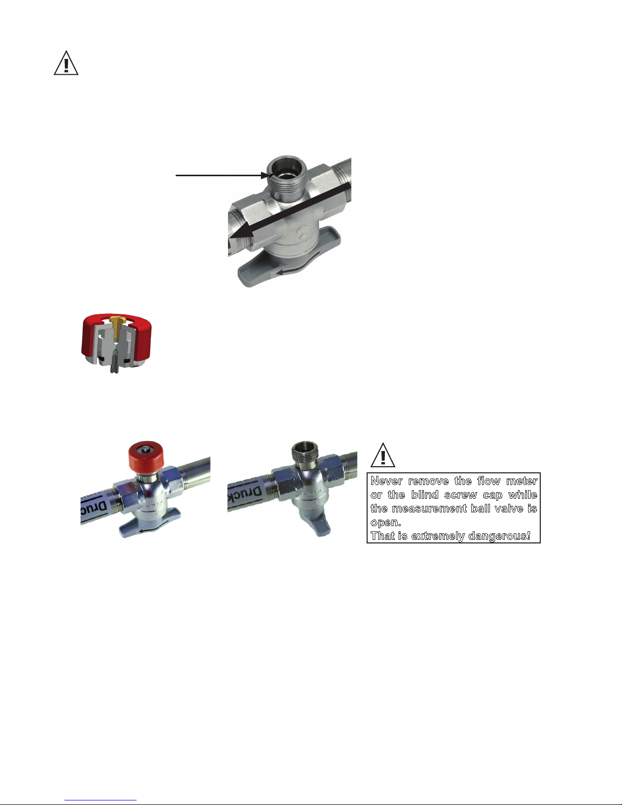
3.5.3. Shut off the measurement ball valve
The measurement ball valve allows for the installation and removal of the flow meter within seconds, with only
a very short interruption of the flow.
OPEN
CLOSED
Never remove the flow meter
or the blind screw cap while
the measurement ball valve is
open.
That is extremely dangerous!
Page 12

12
Make sure that the measurement ball valve is shut off.
•
Remove transport protection cap of the head of the sensing probe.
• Mount the sensing probe in the measurement valve with shut-off function in such a way that the
alignment pin fits in the recess on the measurement ball valve.
• Screw the retainer nut by hand so far that a certain resistance is noticeable.
• Check the correct installation position of the flow meter. The alignment pin must fit in the recess on
the measurement ball valve.
• Tighten the red coloured retainer nut by hand. Tightening by hand should be sufficient. However, if
the seal is not leak tight carefully tighten the nut with an appropriate tool a bit further.
• The mechanical installation of the flowmeter is therewith completed.
Flow Direction
3.5.4. Installation of the flow meter sensing probe
The flow direction is indicated with an arrow on the tip of the probe. Due to the alignment pin is the installation
of the sensing probe in the measurement ball valve only possible in the direction of the flow. After a removal,
the sensing probe will be re-installed in the measurement section in exactly the same position as done at the
factory. Hence, the highest reproducibility is guaranteed.
3.5.5. Removal of the sensing probe of the flowmeter
• Shut off the measurement ball valve (see page 11).
• Turn off the power supply, remove the cover and disconnect the power wires on the screw terminal.
• Loose the retainer nut and pull the sensor probe from the measurement section.
• Operation without the flowmeter installed page 11.
Never remove the flow meter while the measurement ball valve is open.
That is extremely dangerous!
Page 13

13
3.6. Installation KMT-4 in the pipe line
The patented non-return protection device for reliable installation combines three functions in one unit:
• Non-return protection device
The sensor can only be pushed in one direction during installation. The sensor will not move back at all,
even when it is released.
• Seal
Thanks to an encapsulated O-ring, no compressed air can escape under pressure during assembly.
• Precise positioning
The precise positioning with respect to immersion depth and orientation is easy to perform, guaranteeing accurate measurement results.
An example installation is described below using the weld-on nipple in combination with the 1/2“ ball valve.
The same basic principles apply to installation with the tapping sleeve.
• Pull the measurement sensor back into the non-return protection device as far as it will go.
• Screw the non-return protection device into the ball valve using suitable sealants for a fully sealed
connection.
• Screw knurled nut in by approx. one thread turn.
Knurled nut
• Open the ball valve and dip the measurement sensor into the pipe line.
• Positioning in the pipe line
To ensure that the accuracy level specified on the data sheet is observed, the sensor head must
be positioned in the centre of the pipe. The scale on the sensor pipe for the immersion depth
relates to the centre of the sensor head.
ED
12
0,5 * ED
0,5 * ED
ED
X
Immersion depth = x +
ED... External diameter
ED
2
Correct position in the pipe line
Page 14

14
• If the measurement sensor is immersed too far into the
pipe line, it can be retracted by unlocking the non-return
protection device. To do this, slowly press the knurled nut
inwards. As with a pressure point in a car clutch, this
permits the immersion depth to be set to the precise
millimetre.
• Align the measurement sensor with the flow direction.
The flowmeter has a set flow direction. Ensure that the direction arrow on the sensor head or the
mark on the mounting handle is pointing in the media flow direction.
The measurement sensor is aligned with precision in the flow direction using the mounting handle.
An angle deviation must not be greater than ±5° from the ideal position.
Flow direction
CORRECT INCORRECT
Mark for flow
direction
>5°
Align the mounting grip
parallel to the pipe
• When the measurement sensor is correctly positioned in terms of immersion depth and alignment,
tighten the knurled nut with a screw-wrench (AF 27).
• To prevent inadvertent twisting of the probe in use, tighten the grub screw.
Page 15

15
• Connect the measurement sensor and the evaluation unit to the sensor cable.
Sensor cable
Sensor cable
3.7. Setting the pipe diameter
The flowmeter is factory-set so that the average corrected flow speed is measured in the pipe. The standardized
volumetric flow is calculated by the flowmeter as follows:
V
0 = v0 * id
2
*π/4*3600
V0...Standardizedvolumetricow[m3/h]
v0...Standardizedow[m/s]
id...Internaldiameterofpipe[m]
π...3,1415
The internal diameter is factory-set to the value acc. table 1. Because the inner diameter of a pipe is not
standardized and varies depending on wall thickness, the actual inner diameter of the pipe must be set with
the Configurator Software! (see page 35)
Table 1: Factory setting for pipe diameter
da
dis
Nominal
diameter
External
diameter
wall thickness
internal
diameter
DN Inch da (mm/inch) s (mm/inch) di (mm/inch)
50 2" 60.3 / 2.37 2.9 / 0.11 54.5 / 2.15
65 2 1/2" 76.1 / 3.0 2.9 / 0.11 70.3 / 2.77
80 3" 88.9 / 3.5 3.2 / 0.13 82.5 / 3.25
100 4" 114.3 / 4.5 3.6 / 0.14 107.1 / 4.22
125 5" 139.7 / 5.5 4.0 / 0.16 131.7 / 5.19
150 6" 168.3 / 6.63 4.5 / 0.18 159.3 / 6.27
200 8" 219.1 / 8.63 6.3 / 0.25 206.5 / 8.13
250 10" 273.0 / 10.75 6.3 / 0.25 260.4 / 10.25
300 12" 323.9 / 12.75 7.1 / 0.28 309.7 / 12.19
350 14“ 355,6 / 14.00 8 / 0.31 339,6 / 13.37
400 16“ 406,4 / 16.00 8,8 / 0.35 388,8 / 15.31
500 20“ 508 / 20.00 11 / 0.43 486 / 19.13
600 24“ 610 / 24.00 12,5 / 0.49 585 / 23.03
700 28“ 711 / 28.00 14,2 / 0.56 682.6 / 26.87
Page 16

16
4. ELECTRICAL CONNECTIONS
Before electrical connections are made turn off the power supply first. If not observed the electronics can be
damaged as a result.
Only a qualified electrotechnical engineer may install the device.
• Unscrew the four screws and remove the cover of the housing.
• The screw terminals are located in the bottom part of the housing.
• For the electrical connection of the flowmeter a six-wire cable is needed (e.g. 6 x 1 mm
2
(AWG 17))
4.1. Connection diagram
•
Screw terminal OUT 1 -1 for the analogue output is internally connected with GND.
• The housing should be grounded to achieve optimal electromagnetic compliance.
4.1.1. Relay and pulse output, internal switching
The relay switch and pulse outputs are both potential free.
Vcc
OUT 1-2
OUT 1-1
OUT 2-1
OUT 2-2
GND
18...30V AC/DC
+15V
mA_Input
+
-
Modbus data A (=D+) / M-Bus
Modbus data B (=D-) / M-Bus
≅
4...20mA
V
mA
p
I
measuring probe
signal output 1
analogue- or switching output
signal output 2
switching- or pulse output
supply
optional
pressure sensor
or
or
OUT x-1
OUT x-2
Page 17

17
5. CONTROL COMPONENTS
5.1. Jumper for Output
If the signal output is altered from relay to analogue output or vice versa, Jumper Output 1 has to be relocated.
If the analogue output is altered from a current to a voltage output or vice versa, Jumper Out-1 has to be
relocated.
5.2. Digital interface USB (for configuration)
The USB connector is behind the blind screw cap, at the side of the housing.
• remove the blind screw cap with a screwdriver
• plug in the USB connector
Install the configuration software, which is in the scope of supply.
Jumper Output 1
Jumper Out-1
signal output 1 = switching output
analogue output = current signal (e.g. 4-20 mA)
analogue output = voltage signal (e.g 0-10 V)
signal output 1 = analogue output
blind screw cap
USB-cable
Page 18

18
5.3. Display / Indicator with keypad (optional)
An optional two-line display is available for the flowmeter KMT. The display is an integral part of the cover of
the housing and has two soft-keys for the control of the indicator.
KMT
OBOLD
KMT
OBOLD
T : 27.97 °C
V
0
: 1.3 m3/h
V
0
: 323.8 m3/h
Maximal
line 1
line 2
pushbutton - UP
pushbutton - DOWN
Depending on the configuration of the outputs either the measured values, the status of the relay or the consumption is indicated.
KMT
OBOLD
KMT
OBOLD
T : 27.97 °C
V
0
: 1.3 m3/h
V
0
: 323.8 m3/h
Maximal
measurand
measuring value
unit
Measurand SI Unit US Unit
v
0 Standardized Flow m/s SFPM
T Temperature °C °F
V
0 Standardized Volumetric
Flow
m3/h; m3/min; l/min SCFM; SLPM
m Massflow kg/h; kg/min; kg/s kg/h; kg/min; kg/s
Q Consumption m
3
ft
3
p Pressure bar psi
5.3.1. Indication of the analogue and pulse output
Line 1 indicates always the configured measurand at output 1. In line 2 the desired measurement value can
be indicated using the UP and DOWN keys.
5.3.2. Indication of the switch output
Line 1 indicates the status of the switch output. In line 2 the desired measurement value can be indicated
using the UP and DOWN keys.
The display shows an inverse image if the relay output is active (relay has switched).
KMT
OBOLD
KMT
OBOLD
KMT
OBOLD
KMT
OBOLD
T : 27.97 °C
V
0
: 1.3 m3/h
V
0
: 323.8 m3/h
Maximal
V
0
: 1.5 m3/h
Rel : 1
V0: 45.0 m3/h
Rel : 1
KMT
OBOLD
KMT
OBOLD
V
0
: 323.8 m3/h
Maximal
V0: 45.0 m3/h
Rel : 1
Switch output inactive (relay has not switched) Switch output active (relay has switched)
Page 19

19
5.3.3. Indication of the MIN / MAX values
Keep the DOWN key pressed for > 3 sec to indicate the MIN value.
Keep the UP key pressed for > 3 sec to indicate the MAX value.
KMT
OBOLD
KMT
OBOLD
T : 27.97 °C
V
0
: 1.3 m3/h
V
0
: 323.8 m3/h
Maximal
MIN value press pushbutton DOWN >3s
MAX value press pushbutton UP >3s
After that the several different measurement values can be indicated using the UP or DOWN keys.
Keep the DOWN or UP key pressed for > 3 sec to exit the MIN / MAX mode.
KMT
OBOLD
V
0
: 323.8 m3/h
Maximal
5.3.4. Reset of the consumption counter or the MIN / MAX value
Keep both the UP and DOWN key pressed for > 3 sec to enter the menu for resetting the consumption counter or the MIN / MAX value.
Select the desired menu item by pressing the UP or DOWN key briefly.
KMT
OBOLD
V
0
: 323.8 m3/h
Maximal
Press pushbutton UP and DOWN at the same time for >3s
To confirm the selected choice of the menu keep the DOWN or UP key pressed for > 3 sec.
Select menu item “NO” or “EXIT” to cancel without resetting.
KMT
OBOLD
> Clear Consumption
Clear Min/Max
Exit
5.3.5. Maximum consumption counter
The maximum consumption counter readout on the display is 999,999,999.0 m
3
or 99,999,999.0 ft3. Then it
shows “LCD maximum”. The internal memory continues counting. The maximum counter reading is 3.4 * 1038
m3. It is possible to read-out the counter reading with the configuration software.
Page 20

20
6. ERROR MESSAGES
In case the flowmeter is equipped with the optional display, the following error message can be indicated.
ERROR 01: sensing probe is not detected
Cause: the sensing probe is not connect or is defect
Effect: the display indicates “0” for all measurand. The analogue output defaults to the lowest
configured value.
Action: check the head of the sensing probe for visual damage.
check the sensor cable from the sensing probe to the electronics of the signal conditioning.
ERROR 02: the EEprom is defect
Cause: the EEPROM for the storing of the consumption counter and MIN /MAX value is defect.
Effect: the consumption counter and MIN / MAX values are no longer available. All measure-
ment values though are still indicated. The analogue, relay and pulse output are still
functional.
Action: return the flowmeter to the manufacturer.
7. MAINTENANCE
Regular cleaning of the sensor is necessary is used in applications with wet or filthy gases. Cleaning of the
sensor is necessary prior to calibration or evaluation.
7.1. Cleaning of the sensor of the flowmeter
Do not use an abrasive cleaning agent, an organic solvent containing halogen or acetone.
• Clean the head of the sensor probe by carefully swirling in warm water of isopropyl alcohol. It is
recommended to use isopropyl alcohol if the pollution is crease or oil.
The sensor should not be touch by fingers or solid objects like screwdrivers or brushes!
• Leave the sensor to dry in ambient air.
8. REPLACEMENT PARTS / ACCESSORIES
8.1. Order Code Replacement Sensor
Model Design Measuring
range
Measuring section
pipe diameter
Mounting
ERS-KMT-S
1 = Sensor compact
(direction of flow right to left)
1 = low
2 = high
4 = DN15
5 = DN20
6 = DN25
7 = DN32
8 = DN40
9 = DN50
K = for ball valve
2 = Sensor compact
(direction of flow left to right)
3 = remote probe KMT-3 (≤DN50)
4 = remote probe KMT-4 (DN65...DN300) C = DN65...DN100
H = DN125...DN300
F = R1/2“ male at
immersion probe
ERS-KMT-S-116K
Type: Compact ri-le
Working range: 0,90...176 m
3
N
/h for pipe DN 25 (1”)
ERS-KMT-S-316K
Type: remote probe
Working range: 0,90...176 m
3
N
/h for pipe DN 25 (1”)
Order Example Order Example
Page 21

21
8.2. Order Code Replacement sensor cable
only for KMT-3 and KMT-4 (Example: ERS-KMT-K 2)
Model Cable length
ERS-KMT-K
2 = 2 m with plug M12, 4-pin
5 = 5 m with plug M12, 4-pin
Z = 10 m eith plug M12, 4-pin
8.3. Order Code Accessories for KMT-4
Model Description Picture / Drawing
ERS-KMT-AS65
ERS-KMT-AS80
ERS-KMT-AS1H
ERS-KMT-AS1Z
ERS-KMT-AS1F
ERS-KMT-AS2H
ERS-KMT-AS2F
ERS-KMT-AS3H
tapping sleeve DN65
tapping sleeve DN80
tapping sleeve DN100
tapping sleeve DN125
tapping sleeve DN150
tapping sleeve DN200
tapping sleeve DN250
tapping sleeve DN300
ERS-KMT-AN
welding nipple (stainless steel
1.4301) to be weld at the pipe
25
11
G3/4“
Ø18,63
G1/2“
Ø26,67
ERS-KMT-KH
ball valve R½” (brass) mounting
and demounting under pressure
without process interruption
70
82,5
G3/4“
51,5
G1/2“
ERS-KMT-KP
ball valve ½” (brass) for parallel
measurement of pressure or dew
point
70
82,5
5454,5
G3/4“
G1/2“
ERS-KMT-AR15
adapter Rp½” (brass) female to
½” NPT male for process connection
39
NPT1/2“
Ø15
Rp1/2“
SW24
20 19
16
14
Dimensions tapping sleeve (delivery without ball valve)
185
∼115
22
11
25
rubber sealing
NBR 70 Shore
ball valve ERS-KMT-KH
125
G3/4“
Material: stainless steel 1.4301
Threaded nipple
Page 22

22
9. TECHNICAL DATA KMT-1, KMT-2 and KMT-3
Measuring value
Flow
Measurand Volumetric flow at standard conditions acc. DIN 1343
P
0 = 1013.25 mbar; t0 = 0 °C (273.15 K)
Measuring range KMT-x1xx KMT-x2xx
standardized volumetric flow in air
DN15: 0.32...63 Nm3/h 0.19...37.1 SCFM 0.32...126 Nm3/h 0.19...74.1 SCFM
DN20: 0.57...113 Nm3/h 0.34...66.5 SCFM 0.57...226 Nm3/h 0.34...133 SCFM
DN25: 0.90...176 Nm3/h 0.53...103.5 SCFM 0.90...352 Nm3/h 0.53...207.1 SCFM
DN32: 1.45...289 Nm3/h 0.85...170.0 SCFM 1.45...578 Nm3/h 0.85...340 SCFM
DN40 2.26...452 Nm3/h 1.33...265.9 SCFM 2.26...904 Nm3/h 1.33...531.8 SCFM
DN50: 3.50...700 Nm3/h 2.06...411.8 SCFM 3.50...1400 Nm3/h 2.06...823.6 SCFM
standardized flow in air, nitrogen,
argon, CO2 ≤DN50: 0.5...100Nm/s 100...19685 SFPM 0.5...200 Nm/s 100...39370 SFPM
oxygen ≤DN25: 0.5...100Nm/s 100...19685 SFPM 0.5...200 Nm/s 100...39370 SFPM
Accuracy in air at 7 bar (abs) and 23 °C (73 °F)1) ± (1.5% of measuring value + 0.5% of full scale)
Accuracy of temperature compensation ± (0.1% of measuring value/°C)
Response time t90 typ. 1 sec.
Sample rate 0.5 sec.
Temperature
Measuring range
-20...80 °C (-4...176 °F)
Accuracy at 20 °C (68 °F) ± 0.7 °C (1.26 °F)
Outputs
Output signal and display ranges are freely scalable
Analogue output voltage 0 - 10 V max. 1 mA
current (3-wire) 0 - 20 mA and 4 - 20 mA R
L<500 Ohm
Switching output potential-free max. 44 VDC, 500 mA switching capacity
Pulse output Totalizator, pulse length: 0.02...2 sec.
Digital interface USB (for configuration)
Input
Optional pressure compensation 4 - 20 mA (2-wire; 15 V) for pressure sensor
General
Supply voltage 18 - 30 V AC/DC
Current consumption max. 200 mA (with display)
Temperature range ambient temperature: -20...60 °C
(-4...140 °F)
medium temperature: -20...80 °C (-4...176 °F)
storage temperature: -20...60 °C (-4...140 °F)
Nominal pressure up to 16 bar (232 Psi)
Humidity no condensation
Medium compressed air or none corrosive gases
Connection cable gland M16x1.5 (optional connector M12x1 8pol.)
Electromagnetic compatibility EN61326-1 EN61326-2-3
Industrial Environment
Material housing metal (AlSi3Cu)
probe stainless steel
sensor head stainless steel / glass
measurement ball valve brass
Housing protection class IP65 / Nema 4
1) The accuracy statement includes the uncertainty of the factory calibration with an enhancement factor k=2 (2-times standard deviation). The accuracy was
culated in accordance with EA-4/02 and with regard to GUM (Guide to the Expression of Uncertainty in Measurement).
Flow measuring range in dependence on operating pressure
air, nitrogen, oxygen, argon
CO
2
Formula for calculating the standardized
volumetricow:
QN = VN * id2*π/4*3600
QN...standardizedvolumetricow[m3/h]
VN...standardizedow[m/s]
id...innerpipediameter[m]
π...3.1415
Nm/s
operatingpressure[bar]
Page 23

23
Factory setting of outputs KMT-1, KMT-2 and KMT-3
SI-Unit
Analogue output
[0...10V/0(4)...20mA] from to unit
KMT-x1... KMT-x2...
standardized DN15: 0 60 120 Nm
3
/h
volumetric flow DN20: 0 110 220 Nm3/h
DN25: 0 175 350 Nm3/h
DN32: 0 285 570 Nm
3
/h
DN40: 0 450 900 Nm3/h
DN50: 0 700 1400 Nm3/h
mass flow DN15: 0 75 150 kg/h
DN20: 0 140 280 kg/h
DN25: 0 220 440 kg/h
DN32 0 360 720 kg/h
DN40: 0 570 1140 kg/h
DN50: 0 890 1780 kg/h
standardized flow
≤DN50 0 100 200 Nm/s
temperature
all Ø -20 80 80 °C
Switchingoutput [switchingpoint/hysteresis]
standardized DN15 50/5 100/10 Nm3/h
volumetric flow DN20 90/9 180/18 Nm3/h
DN25: 150/15 300/30 Nm3/h
DN32: 230/23 460/46 Nm3/h
DN40: 360/36 720/72 Nm
3
/h
DN50: 560/56 1120/112 Nm3/h
mass flow DN15: 60/6 120/12 kg/h
DN20: 110/11 220/22 kg/h
DN25: 200/20 400/40 kg/h
DN32: 290/29 580/58 kg/h
DN40: 460/46 920/92 kg/h
DN50: 700/70 1400/140 kg/h
standardized flow
≤DN50 80/8 180/18 Nm/s
temperature all Ø 30/3 70/7 °C
US-Unit
Analogue output [0...10V/0(4)...20mA] from to unit
KMT-x1... KMT-x2...
standardized DN15: 0 35 70 SCFM
volumetric flow DN20: 0 60 120 SCFM
DN25: 0 100 200 SCFM
DN32: 0 165 330 SCFM
DN40: 0 260 520 SCFM
DN50: 0 410 820 SCFM
mass flow DN15: 0 75 150 kg/h
DN20: 0 140 280 kg/h
DN25: 0 220 440 kg/h
DN32 0 360 720 kg/h
DN40: 0 570 1140 kg/h
DN50: 0 890 1780 kg/h
standardized flow
≤DN50 0 20000 40000 SFPM
Temperatur alle Ø -4 176 176 °F
Switchingoutput [switchingpoint/hysteresis]
standardized DN15 30/3 60/6 SCFM
volumetric flow DN20 50/5 100/10 SCFM
DN25: 80/8 160/16 SCFM
DN32: 130/13 260/26 SCFM
DN40: 210/21 420/42 SCFM
DN50: 330/33 660/66 SCFM
mass flow DN15: 60/6 120/12 kg/h
DN20: 110/11 220/22 kg/h
DN25: 200/20 400/40 kg/h
DN32: 290/29 580/58 kg/h
DN40: 460/46 920/92 kg/h
DN50: 700/70 1400/140 kg/h
standardized flow
≤DN50 15000/1500 30000/3000 SFPM
temperature
all Ø 90/9 150/15 °F
Page 24

24
10. TECHNICAL DATA KMT-4
Measuring value
Flow
Measurand Volumetric flow at standard conditions acc. DIN 1343
P
0 = 1013.25 mbar (14.7 PSI); t0 = 0 °C (32 °F)
Measuring range 0.2...100 Nm/s (40...19685 SFPM) or 0.2...200 Nm/s (40...39370 SFPM)
Accuracy in air at 9 bar (130.5 psi) (abs) and 23 °C (73 °F)
1)
± (1.5 % of measuring value + 0.8 % of full scale)
Temperature coefficient ± (0.1 % of measuring value / °C)
Pressure coefficient
2)
+ 0.5 % of measuring value / bar
Response time t
90 < 1 sec.
Sample rate 0.5 sec.
Temperature
Measuring range
-20...80 °C (-4...176 °F)
Accuracy at 20 °C (68 °F) ± 0.7 °C (1.26 °F)
Outputs
Output signal and display ranges are freely scalable
Analogue output voltage 0 - 10 V max. 1 mA
current (3-wire) 0 - 20 mA and 4 - 20 mA R
L<500 Ohm
Switching output potential-free max. 44 VDC, 500 mA switching capacity
Pulse output Totalizer, pulse length: 0.02...2 sec.
Digital interface USB (for configuration)
Input
Optional pressure compensation 4 - 20 mA (2-wire; 15 V) for pressure sensor
General
Supply voltage 18 - 30 V AC/DC
Current consumption max. 200 mA
Temperature range ambient temperature: -20...60 °C
(-4...140 °F)
medium temperature: -20...80 °C (-4...176 °F)
storage temperature: -20...60 °C (-4...140 °F)
Humidity working range 0...99 %RH no condensation
max. working pressure 16 bar
(232 psi)
Medium compressed air or Non-Corrosive gases
Electrical connection cable gland M16x1.5
Electromagnetic compatibility EN61326-1 EN61326-2-3
Industrial Environment
Material housing metal (AlSi3Cu)
probe stainless steel
sensor head stainless steel / galss
non-return protection brass
Housing protection class IP65 / Nema 4
1) The accuracy statement includes the uncertainty of the factory calibration with an enhancement factor k=2 (2-times standard deviation). The accuracy was
culated in accordance with EA-4/02 and with regard to GUM (Guide to the Expression of Uncertainty in Measurement).
2) The flow meter is calibrated at 9 bar (abs) 130.5 psi. If the working pressure is different from 9 bar (130.5 psi) you can compensate the error by setting the actual pressure with the configuration software.
Flow measuring range in dependence on pipe diameter
pipe inner Ø measuring range
mm
(inch) 0.2...100 Nm/s (40...19685 SFPM) 0.2...200 Nm/s (40...39370 SFPM)
DN50 / 2“ 54.5
(2.15“) 1.7...839 Nm
3
/h 1.0...493.8 SCFM 1.7...1679 Nm3/h 1.0...987.6 SCFM
DN65 / 2 1/2“ 70.3 (2.77“) 2.8...1397 Nm3/h 1.6...821.6 SCFM 2.8...2793 Nm3/h 1.6...1643.2 SCFM
DN80 / 3“ 82.5 (3.25“) 3.8...1923 Nm3/h 2.3...1131.5 SCFM 3.8...3847 Nm3/h 2.3...2263.0 SCFM
DN100 / 4“ 107.1 (4.22“) 6.5...3242 Nm3/h 3.8...1906.9 SCFM 6.5...6483 Nm3/h 3.8...3813.8 SCFM
DN125 / 5“ 131.7 (5.19“) 9.8...4902 Nm3/h 5.8...2883.5 SCFM 9.8...9803 Nm3/h 5.8...5766.9 SCFM
DN150 / 6“ 159.3 (6.27“) 14.3...7171 Nm3/h 8.4...4218.7 SCFM 14.3...14343 Nm3/h 8.4...8437.3 SCFM
DN200 / 8“ 206.5 (8.13“) 24.1...12051 Nm3/h 14.2...7089.0 SCFM 24.1...24101 Nm3/h 14.2...14178.0 SCFM
DN250 / 10“ 260.4 (10.25“) 38.3...19163 Nm3/h 22.5...11272.6 SCFM 38.3...38325 Nm3/h 22.5...22545.3 SCFM
DN300 / 12“ 309.7 (12.19“) 54.2...27105 Nm3/h 31.9...15945.1 SCFM 54.2...54211 Nm3/h 31.9...31890.1 SCFM
DN350 / 14“ 339.6 (13.37“) 65.2...32591 Nm3/h 38.3...19172.5 SCFM 65.2...65183 Nm3/h 38.3...38345.0 SCFM
DN400 / 16“ 388.8 (15.31“) 85,4...42719 Nm3/h 50.3...25130.2 SCFM 85.4...85438 Nm3/h 50.3...50260.0 SCFM
DN500 / 20“ 486 (19.13“) 133,5...66749 Nm3/h 78,5...39266.0 SCFM 133.5...133498 Nm3/h 78,5...78531.9 SCFM
DN600 / 24“ 585 (23.03“) 193,4...96712 Nm3/h 113.8...56892.6 SCFM 193.4...193425 Nm3/h 113.8...113785.1 SCFM
DN700 / 28“ 682.6 (26.87“) 263,4...131675 Nm3/h 154.9...77459.8 SCFM 263.4...263350 Nm3/h 154.9...154919.6 SCFM
Page 25

25
Factory setting analogue output
Analogue output [0...10V/0(4)...20mA]
standardized volumetric flow standardized volumetric flow mass flow
pipe inner Ø from up to unit up to unit up to unit
DN Zoll di (mm) low (L1) high (H2) low (L1) high (H2) low (L1) high (H2)
50 2" 54,5 0 800 1600 Nm
3
/h 450 900 SCFM 1035 2070 kg/h
65 2 1/2" 70,3 0 1300 2600 Nm
3
/h 800 1600 SCFM 1682 3364 kg/h
80 3" 82,5 0 1900 3800 Nm
3
/h 1100 2200 SCFM 2458 4916 kg/h
100 4" 107,1 0 3200 6400 Nm
3
/h 1900 3800 SCFM 4140 8280 kg/h
125 5" 131,7 0 4900 9800 Nm
3
/h 2800 5600 SCFM 6339 12678 kg/h
150 6" 159,3 0 7100 14200 Nm
3
/h 4200 8400 SCFM 9185 18371 kg/h
200 8" 206,5 0 12000 24000 Nm
3
/h 7000 14000 SCFM 15524 31049 kg/h
250 10" 260,4 0 19000 38000 Nm
3
/h 11000 22000 SCFM 24580 49161 kg/h
300 12" 309,7 0 27000 54000 Nm
3
/h 15000 30000 SCFM 34930 69860 kg/h
350 14“ 339,6 0 32000 64000 Nm
3
/h 19000 38000 SCFM 41398 82797 kg/h
400 16“ 388,8 0 42000 84000 Nm
3
/h 25000 50000 SCFM 54335 108671 kg/h
500 20“ 486 0 66000 132000 Nm
3
/h 39000 78000 SCFM 85384 170768 kg/h
600 24“ 585 0 96000 192000 Nm
3
/h 56000 112000 SCFM 124195 248390 kg/h
700 28“ 682,6 0 130000 260000 Nm
3
/h 77000 154000 SCFM 168181 336362 kg/h
Page 26

26
CONFIGURATION SOFTWARE
LIMITED LIABILITY
KOBOLD shall not be held liable for any damages or consequential damages (for example, but not restricted
to, loss of earnings, interruption of business, loss of information and data or any other financial losses) resulting from the installation, use or impossibility of use of an KOBOLD software product and any associated support services or non-performance of support services.
1. General
The configuration software, in the scope of supply, allows for a user-friendly adaptation of the flowmeter to the
application. In addition, the measurement values for flow and temperature can be calibrated / adjusted.
The system requirements for the installation and execution of the software are:
• Windows XP with SP3, Windows Vista or Windows 7
• .NET framework 3.5 with SP1
• USB 2.0 interface
During setup there will be no installation of .NET Framework 3.5 SP1 – if the required version is not already
installed on the computer the following error message will appear at the start of the configuration software.
.NET Framework 3.5 SP1 can be installed using Windows Update.
2. Installation
In order to set up a smooth installation of the configuration software of the KMT, admin authorization for the
personal computer is required.
• Place the CD-ROM in the drive tray of the computer.
• At this moment the KMT should NOT be connected with the USB cable to the computer.
• The setup program will start automatically with the Auto Run-function – in case the program does
not start automatically, one can start the setup software manually by starting Setup.exe directly.
• The InstallShield-Wizard for the KMT configurator will be started.
• Follow the instructions on the screen to install the software.
At first, the configuration software will be installed and then the installation of the USB driver activated – except
if the user has defined that USB setup is disabled.
The USB driver will be automatically installed the moment the first connection is made with the KMT.
The appearing dialog boxes can be dealt with the settings “No. do not download driver from the internet” and
“Install the hardware automatically”.
If the KMT configuration software and the USB driver are installed correctly, and the KMT is connected via the
USB interface with the personal computer, a connection “Silicon Labs
CP210x USB to UART Bridge” should have been created in the device
manager.
See: Start => Settings => Control Panel => System => Hardware => Device
Manager
Page 27

27
2.1. Configuration of the USB Interface (VirtualCOM)
After the startup of the software, the correct VirtualCOM interface for the
USB driver must be configured
The number for the used USB interface can be found under:
Start => Settings => Control Panel => System => Hardware => Device
Manager
The setting is done under menu “Extras” and menu item “Optional extras…..”
Select the COM-port number as shown in the device manager.
These settings are done only once and at the first start of the configuration software. The settings are stored
for future use.
Page 28

28
3. User Interface
1
4
2
3
4
1
2
3
Basic information:
After retrieving the data from the transmitter, the basic information of the device is shown here.
Status message:
Here are the messages shown about the status and other information.
Input screen:
Input screen for the configuration or adjustment of the flow meter.
Menu tool bar:
Selection of menu items.
4. Menu toolbar
4.1. File
Delete status message deletes the status messages.
Exit closes the configuration software.
Page 29

29
4.2. Transmitter
Read reads the actual configuration of the transmitter.
Send uploads the ‘new’ configuration to the transmitter.
The following settings are uploaded to the transmitter
• Units
• Output 1
• Output 2
• Display mode
• Pressure transmitter
Prior to uploading the ‘new’ configuration to the transmitter, a dialog box will show a summary of the
changes. Click on the button ‘OK’ and the configuration will be uploaded to the transmitter; click
‘Cancel’ to cancel the operation.
4.3. Extras
Configurations of the VirtualCOM- interface (see page 27).
5. Input Screen
5.1. Output 1, Output 2
In this screen the actual settings of the transmitter for the output 1 and 2, resp. relay 1 and 2 are shown. The
user can alter and upload these settings to the transmitter, together with other changes of the configuration.
5.1.1. Output mode
Here the mode of signal output can be determined.
Output 1: analogue or switch (relay) output
Output 2: switch (relay) or pulse output
NOTE:
In case the mode of output 1 is changed, the Jumper J1 on the board of the signal conditioning electronics has to
be relocated as well (see page 29)
5.1.2. Measurand
Here is determined which measurand will be represented at the particular output.
5.1.3. Units
Choice of the engineering units of the selected measurand in either SI- (m/s; °C; m3/h) or US-units
(SFPM; °F; SCFM).
NOTE:
The setting “Units” on the tabs for Output 1 and Output 2 are in sync with each other. If the units are changed
on one of the output tabs, automatically the units on the other output tab are changed accordingly.
5.1.4. Output mode – analogue
Within the limits of measurement range and the scaling of the output, the analogue output can be freely configured and scaled. Either a standard output signal (0 – 5 V, 0 – 10 V, 0 – 20 mA, 4 – 20 mA) can be selected
or a user defined range for the current / voltage output (e.g. 1 – 9 V).
NOTE:
In case the analogue output is changed (from current to voltage or vice versa), the Jumper J2 on the board
of the signal conditioning electronics has to be relocated as well (see page 29).
Page 30

30
5.1.5. Output mode – switch (relay)
In the field for the “Switch-mode”, one can select “Hysteresis” or “Window”.
The field for “Type” is to determine the switch action of the relay, NO = Normally Open (activate to close), NC
= Normally Close (activate to open).
Under “Measuring range” in the field “From” the low value of the measuring range can be entered and in the
field “To” the high value.
The hysteresis of the set point is entered as a percentage of the
measuring range.
[measuringrange]=highmeasuringvalue–lowmeasuringvalue
e.g. hysteresis
set point = 500 Nm3/h and reset point is 450 Nm3/h
Hysteresis = 50 Nm3/h = 0.5 % of measuring range
Hysteresis
t
Nm3/h
0
1
0
1
NC (activate to open)
NO (activate to close)
set point 1
Hysteresis
When the measurement value reaches set point 1, the relay will be
activated. The value at the reset point is the value at set point 1
minus the hysteresis.
e.g. set point 1 = 100 Nm3/h and the hysteresis 5 Nm3/h.
the relay switches at 100 Nm3/h. The reset point is at 96 Nm3/h.
Hysteresis = 5 Nm3/h = 5% of the measuring range
Window
t
Nm3/h
0
1
0
1
set point 1
set point 2
NC (activate to open)
NO (activate to close)
The relay is activated as long as the measuring value is
between the values of set point 1 and set point 2.
The hysteresis of each set point is fixed at 0.2% of the measuring range.
e.g.: set point 1 = 100 Nm3/h; set point 2 = 80 Nm3/h;
hysteresis of each set point is 1 Nm3/h (0.2% of 500 Nm3/h)
80 Nm3/h = set point 2
100 Nm3/h = set point 1
99 Nm3/h = set point 1 - hysteresis
79 Nm3/h = set point 2 - hysteresis
Page 31

31
5.1.6. Output mode – pulse
If output 2 is configured for pulse, the measurand can be consumption only. Under “Pulse”, the duration of the
pulse and the pulse value (Significance level of pulse) can be freely configured.
VolumeFlow[m3/h] Number of Pulses
HourPulseValue[m
3
/Pulse]
=
The duration of the pulse can be set between 0.02 and 2 seconds.
e.g. Duration of pulse = 100ms; one pulse for each Nm3 consumed
The pulse – interval – ratio must be at least 1 : 2, meaning that the duration of the pulse interval must be at
least twice the duration of the pulse itself.
t
OUT 2
1/3 min. 2/3
≥ 2 s
Calculation of the minimum “pulse value” or the maximum “pulse duration”.
IMPW_MIN=NORMV_MAX[m3/h]*IMPL[s]/1200
IMPL_MAX=IMPW[m3]*1200/NORMV_MAX[m3/h]
IMPW pulsevalue[m
3
]
IMPL pulselength(duration)[s]
IMPW_MIN minimumpulsevalue[m3]
IMPL_MAX maximum pulse length (duration)
NORMV_MAX expected maximum volume flow (NM3/h)
5.2. Minimum flow shutdown
The minimum flow shutdown is switched on and off using the “active” checkbox.
Iftheoutputsignalis≤thantheset“Shutdownvalue”,theflowmeterissues0ontheanalogueoutput.
5.3. Display
If an optional display is installed, at the tab Display the following items can be entered:
Drop-down input field “Display-Mode”
• Single spaced
• Double spaced (default)
Checkbox “Backlight”
• Checked = ON
• Unchecked = OFF
In the input field “Description (free
text), a user specific name (max. 16
characters) for the transmitter can be
entered.
e.g.: HALL 1
With the button “send” only the description will be uploaded to the transmitter.
Page 32

32
5.4. Adjustment
The user can perform an adjustment for the measurands normflow and temperature in air.
The configuration software distinguishes between a 1-point and a 2-point adjustment automatically, depending
on how many reference points for adjustments are entered.
The values entered for the customer’s adjustment are stored in the electronics of the sensing probe and are
therefore not lost if the electronics of the signal conditioning are replaced (see page 6)
If the checkbox “Performing customer-adjustment” is checked, the adjustment mode will be activated and the
actual measuring value in the set interval automatically retrieved from the flowmeter (transmitter).
NOTE:
While the customer-adjustment is active all other pages, functions and commands are deactivated.
In the field “Adjustment” the measurand to be adjusted is selected.
In the field “Measuring value” the actual measurement value of the transmitter is indicated.
The update-interval can be set.
In the field “Reference value” the measurement value of the standard is entered.
After clicking the button “send” a control dialog box appears in which the values can be corrected if needed.
Then the reference value will be uploaded to the flowmeter (transmitter) and is the adjustment procedure
complete.
The reference point of the customer-adjustment must be within the determined measuring range.
The customer-adjustment results in a slight rotation of the characteristic line, in such a way that the measurement deviation at the upper and lower adjustment points equals zero.
The configuration software determines, depending on its position, if it is an upper or lower adjustment point.
5.4.1. 1-point adjustment
lower adjustment point upper adjustment point
possibility 1 0 - 50% of measuring range 100% of measuring range
possibility 2 0% of measuring range >50 - 100% of m.r.
m.r. ... measuring range
10% 20% 30% 40% 50% 60% 70% 80% 90% 100%
100%
90%
80%
70%
60%
50%
40%
30%
20%
10%
upper adjustment point at 80% of measuring range
lower adjustment point automatically at 0% of m.r.
characteristic line before adjustment
selected adjustment point
characteristic line after adjustment
measuring range
output signal
10% 20% 30% 40% 50% 60% 70% 80% 90% 100%
100%
90%
80%
70%
60%
50%
40%
30%
20%
10%
lower adjustment point at 20% of measuring range
upper adjustment point automatically at 100% of m.r.
selected adjustment point
characteristic line before adjustment
measuring range
output signal
characteristic line after adjustment
Page 33

33
5.4.2. 2-point adjustment
With a 2-point adjustment procedure the lower adjustment point must be between 0 and 40% of the measuring range, and the upper adjustment point between 60 and 100% of the measuring range. If the adjustment
point is between 40 and 60% of the measuring range, automatically a 1-point adjustment procedure will be
executed instead.
lower adjustment point upper adjustment point
possibility 1 0 - <40% of m.r. 60 - 100% of m.r.
possibility 2 40 - <50% of m.r. 100% of m.r.
possibility 3 0% of m.r. 50 - <60% of m.r.
10% 20% 30% 40% 50% 60% 70% 80% 90% 100%
100%
90%
80%
70%
60%
50%
40%
30%
20%
10%
lower adjustment point at 10% of measuring range
upper adjustment point at 90% of measuring range
characteristic line before adjustment
characteristic line atfer adjustment
measuring range
output signal
5.4.3. Reset to factory settings
Customer-adjustment can be reset to the factory settings by checking the appropriate checkbox and subsequently clicking the “reset” button.
Page 34

34
5.5. Measuring values overview
The tab measuring values provides an overview of the retrieved actual measurement values of the flowmeter (transmitter). Clicking on “Fetch values” will retrieve the actual measurement and MIN / MAX values for
flow, volume flow, temperature, mass flow and pressure (only if a pressure transmitter is connected) from the
transmitter – additional the reading of the consumption meter is retrieved as well.
Checking the “Polling” checkbox will retrieve the measuring data from the transmitter at the selected interval.
5.5.1. Reset of the MIN / MAX values
The MIN/ MAX values of each measurand, as stored in the flowmeter (transmitter), can be reset by checking
the appropriate checkbox and subsequently clicking the “Clear MIN / MAX” button.
5.5.2. Reset of the consumption counter (totalizer)
The reading of the consumption meter can be reset by clicking the “Reset meter” button.
5.6. Setting up Process Parameters
In the tab Process Parameters you can change the Process gas (medium) and set the pressure compensation
5.6.1. Change the Process Gas
NOTE: This function is only active if the flow meter for a medium different from air has been ordered (see
order code Medium in the data sheet)
Calibration-Gas: Is the gas (medium) in which the flow meter was calibrated in the factory. Unless otherwise
specified, the flowmeter is calibrated at the factory always in air.
Process-Gas: Is the gas (medium) in the measured process. The adjustable process gases are set at the
factory and can be selected from a list.
The flow meter is factory set to the ordered gas (medium).
If the setting for the process-gas modified or changed between calibration- and process gas, the changed
setting has to be sent to the transmitter. Use “send data to the transmitter and read ...” button.
The “active gas” to which the flow meter is set, you can see in the field basic information.
Page 35

35
5.6.2. Changing the standard conditions
The flowmeter is factory-set to standard conditions conforming to DIN 1343.
Factory setting: P
0
= 1013.25 mbar, t0 = 0°C (273.15 K)
The corrected volume flow measured value is calculated in line with the standard conditions set.
5.6.3. Pressure compensation
In order to achieve the highest accuracy the actual process pressure can be entered in the field “process pressure”.
Clicking the button “send” only the value of the process pressure will be uploaded to the flowmeter (transmitter).
5.6.4. Setting the pipe diameter
The actual inner diameter of the pipe must be set here. The “Send” button is used only to send the pipe
diameter to the transmitter.
5.7. External pressure transmitter for pressure compensation
In order to achieve the highest accuracy, the input from an external pressure transmitter will be very useful if
the pressure fluctuates strongly (e.g. 3 to 10 bar (45 to 150 psi)). An absolute pressure transmitter with a
2-wire loop powered 4 – 20 mA output should be used.
On the tab “Pressure transmitter” the measuring range can be entered.
5.8. Declaration of Conformance
EU Declaration of Conformance
We, KOBOLD Messring GmbH, Hofheim-Ts, Germany, declare under our sole
responsibility that the product:
Flow Meter for compressed air and gases Model: KMT
to which this declaration relates is in conformity with the standards noted below:
EN 61326-1:2013 Electrical equipment for measurement, control and
laboratory use - EMC requirements - Part 1: General requirements
EN 61326-2-3:2013 Electrical equipment for measurement, control and
laboratory use - EMC requirements - Part 2-3: Particular requirements - Test
configuration, operational conditions and performance criteria for transducers with
integrated or remote signal conditioning
EN 50581:2012 Technical documentation for the assessment of electrical
and electronic products with respect to the restriction of hazardous substances
Also the following EC guidelines are fulfilled:
2014/30/EU EMC Directive
2011/65/EU RoHS (category 9)
Hofheim, 08 March 2018
H. Peters M. Wenzel
General Manager Proxy Holder
Page 36

www.kobold.com
 Loading...