

Page 1
Operating Instruction
for
Electronic Flow Meter / Monitor
Compact Version
Model: KAL-A
KAL-AK
Page 2

KAL-A(K)
1. Contents
...Contents ........................................................................................................ 2
1.
2....Note .............................................................................................................. 3
3....Instrument Inspection .................................................................................... 3
4....Regulation Use .............................................................................................. 3
5....Operating Principle ........................................................................................ 4
6....Mechanical Connection ................................................................................. 5
7....Electrical Connection .................................................................................... 5
8....Output ........................................................................................................... 8
9....Commissioning .............................................................................................. 9
10..Maintenance ............................................................................................... 12
11..Diagnostics ................................................................................................. 12
12..Technical Information .................................................................................. 12
13..Order Codes ............................................................................................... 13
14..Dimensions ................................................................................................. 14
15..EU Declaration of Conformance .................................................................. 15
Manufactured and sold by:
Kobold Messring GmbH
Nordring 22-24
D-65719 Hofheim
Tel.: +49(0)6192-2990
Fax: +49(0)6192-23398
E-Mail: info.de@kobold.com
Internet: www.kobold.com
Page 2 KAL-A(K) K05/1116
Page 3

KAL-A(K)
2. Note
Please read these operating instructions before unpacking and putting the unit
into operation. Follow the instructions precisely as described herein.
The devices are only to be used, maintained and serviced by persons familiar
with these operating instructions and in accordance with local regulations
applying to Health & Safety and prevention of accidents.
When used in machines, the measuring unit should be used only when the
machines fulfil the EC-machine guidelines.
3. Instrument Inspection
Instruments are inspected before shipping and sent out in perfect condition.
Should damage to a device be visible, we recommend a thorough inspection of
the delivery packaging. In case of damage, please inform your parcel service /
forwarding agent immediately, since they are responsible for damages during
transit.
4. Regulation Use
The KOBOLD KAL-A.. Flow Meter is intended for use in measuring moderate
flow rates of low-viscous or dirty liquids.
The KOBOLD KAL-AK.. Flow Meter is intended for use in measuring and
monitoring moderate flow rates of low-viscous or dirty liquids.
Analogue Output / Limiting Signal
For measuring the flow rate of the liquids the device is equipped with a 4-20 mA
output signal. Additionally the model KAL-AK.. is equipped with a limit switch
(NPN or PNP).
Trend Display
A LED bar graph display indicates the current flow rate and the set point
(KAL-AK) via a flashing LED.
Sensor
The model KAL-A and KAL-AK consists of a sensor with integrated electronic.
The devices may only be used for liquids to which the probe material is resistant.
With proper installation and maintenance, the probes are not sensitive to soiling
and cause practically no pressure loss.
KAL-A(K) K05/1116 Page 3
Page 4
KAL-A(K)
Materials
Sensor Stainless steel (1.4301, 1.4305, 1.4571)
Electronic cover Glass fibre reinforced polyamide
Setting ranges
in relation to nominal tube diameter
ID (mm) Meas. range (L/min) water ID (mm) Meas. range (L/min) water
8 0.12 - 6.0 40 3.0 - 150
10 0.19 - 9.4 50 4.7 - 235
15 0.42 - 21.8 60 6.8 - 340
20 0.75 - 37.7 80 12.0 - 603
25 1.18 - 59.0 100 18.8 - 942
30 1.7 - 84.8 150 42.4 - 2120
Attention! The flow ranges specified in the table above have been
calculated for each pipe diameter based on the known velocity
range of the KAL-A(K). It must be noted that flow in pipes is nonuniform across the pipe cross section, and approaches zero at the
pipe wall. This means that, in practice, the depth of installation of
the probe, the internal pipe diameter, and the flow profile of the
liquid in the pipe can interact to produce significant deviations from
the flow ranges in the above table.
5. Operating Principle
The KAL-A... Flow Meter/ -Monitor uses the proven thermal dispersion principle
and operates as follows: The probe is heated internally to a few degrees above
the temperature of the medium into which it extends. The flowing medium takes
this heat off the probe, i.e. the probe is cooled down. The cooling rate is
proportional to the flow rate. The electronic converts the signal into a proportional
current signal (4-20 mA) linear to the flow rate. With model KAL-AK the requested
flow rate will be compared with the flow rate existing and if the set- point is
reached a PNP/NPN switch is activated. The microprocessor-controlled design
permits simple calibration and set-up. The compact probe design permits
monitoring of flow rate with minimum pressure loss.
Page 4 KAL-A(K) K05/1116
Page 5
KAL-A(K)
6. Mechanical Connection
Prior to installation
Ensure that the actual system flow rate the is within the measuring range of
the KAL-A(K).
Ensure that the maximum system temperature and pressure are within the
limits specified per section (see section 12. Technical Information)
Fitting
Mount the sensor into the piping and make sure that it is completely filled with
fluid. The probe tip has to reach at least 5 mm (better > 5 mm) into the pipe (see
below).
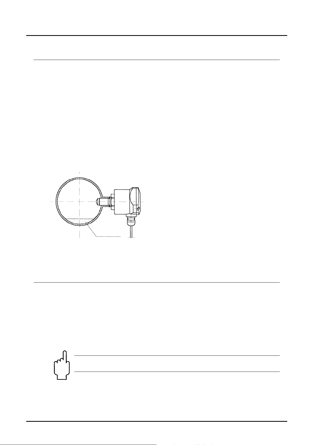
Fitting position
The sensor can be mounted in any orientation
as long as the piping is completely filled with
fluid. The mounting position has to be smooth
and free of turbulence.
(Recommended input and output length: 5 x
pipe diameter, of straight - run piping both
upstream and downstream of the flow switch).
In case of sediments in the pipe the shown
Se dim e nts
mounting position is recommended.
7. Electrical Connection
Screw in sensor.
Remove electronic cover.
(The fixing screws are secured against falling out)
Strip 4-wire cable (approx. 40-60 mm) and pull through cable gland.
Tighten cable gland.
Connect wires to terminal connector block according to their functions.
Ensure that the power is disconnected during the connection of the cable.
Attention! SET-pushbutton must not be pressed while switching
supply voltage on.
After connection, apply supply voltage of 24 VDC ± 20% (see Technical
Information)
KAL-A(K) K05/1116 Page 5
Page 6

KAL-A(K)
Flood piping in which the sensor has been mounted with medium.
Check the sensor thread for tightness.
Check function of electronic (set-point LED must flash)
Calibrate flow switch (see 9. Commissioning)
Function elements
Output Selector Switch
NPN/PNP
Attention! Ensure that the voltage of your installation corresponds
to the voltage values given on the device's specification plate.
Trend Indicator
(8 LEDs)
Set point Potentiometer
P1
Terminal Strip
1: Output NPN/PNP
2: GND
3: +24 VDC
4: 4...20 mA
LED Trend Indicator
The LED Trend Indicator (8 LEDs) is used to indicate the flow rate (LED,
starting left). For model KAL-AK the adjusted switching point is additionally
indicated by a flashing LED.
If the flow rate has reached the set point value selected by the user, then the
LED is flashing.
Bi-coloured LED (KAL-A)
If bi-coloured LED is green: Instrument is in operation mode.
If bi-coloured LED is flashing green: Instrument is in calibration mode.
If bi-coloured LED is flashing red: Instrument signal an error (check the
temperature of the liquid).
SET-Push button
(calibration)
Bi-coloured LED
red = ALARM
green = FLOW
(above set point)
Cable gland
Page 6 KAL-A(K) K05/1116
Page 7

KAL-A(K)
Bi-coloured LED (KAL-AK)
The bi-coloured LED serves to additionally display a switching point (KAL-AK).
RED = ALARM (flow below the set point)
GREEN = (flow above the set point)
If bi-coloured LED is flashing green: Instrument is in calibration mode.
If bi coloured LED is flashing red: Instrument signal an error (check the
temperature of the liquid ).
Terminal strip
The terminal strip serves the electrical connection.
The device only operated with 24 VDC (DC ± 20%)
Terminal 1: Output NPN/PNP (only KAL-AK)
Terminal 2: GND
Terminal 3: + 24 VDC
Terminal 4: Analogue output
Plug connector M12
Output NPN/PNP
(only for KAL-AK)
2
1
3
GND
4
SET pushbutton
The calibration switch is used to start the flow calibration procedure
Potentiometer
a.) Calibration: left-hand stop = zero flow calibration
right-hand stop = maximum flow calibration
b.) Switching point adjustment (KAL-AK)
The set point potentiometer is used to adjust the flow set point. You will
notice that the flashing LED moves along the trend indicator scale as the set
point potentiometer is adjusted.
Output Selector Switch
The output selector switch is used to select between the output logic NPN and
PNP. This adjustment is factory-made and needs not to be changed anymore
under normal conditions.
Output selector switch right: NPN-output
Output selector switch left: PNP-output
24 V
DC
4-20 mA
KAL-A(K) K05/1116 Page 7
Page 8

KAL-A(K)
8. Output
Analogue output
The analogue output supplies a current signal proportional to the flow rate
(0-100% = 4-20 mA). Terminal 2 is the bench mark of the analogue output
GROUND (0 VDC).
Switching point (KAL-AK)
The output characteristics of the switch logic will be customised by the factory.
NPN-output
The semiconductor output switches to GND (GROUND = 0 VDC) or is highly
resistant. The maximum output current is 400 mA.
The reference point for the NPN-output is +24 VDC.
PNP-output
The semiconductor output switches to +24 VDC or is highly resistant. The
maximum output current is 400 mA.
The reference point for the PNP-output is GND (GROUND = 0 VDC).
Page 8 KAL-A(K) K05/1116
Page 9

KAL-A(K)
N/O function (KAL-AK)
In the N/O function the output is switching into the low resistance state
(PNP +24 VDC impress on the output; NPN GND 0 VDC impresses on the
output), if the actual value has reached or exceeded the set point
At the same time the green LED is flashing.
If the actual value is falling below the set point, then the output will become highly
resistant and the red LED will flash ( = ALARM-condition).
In case of a break-down of the power supply the output will be switched to highly
resistant (ALARM-condition).
9. Commissioning
The use of this meter in machines according to directive 89/392/EWG is
prohibited until the complete machine complies to this directive.
After mechanical (“Mechanical Connection”) and electrical (“Electrical
Connection”) installation of the sensor the flow meter has to be put into operation
as described in this section.
Calibration
a) Zero flow calibration
Stop the flow of the liquid in the piping in which the sensor is installed. It is
important that the sensor tip be immersed in the liquid. There should be no
bubbles around the sensor tip.
Turn set point adjustment potentiometer counter clockwise to its far left-hand
stop and now briefly press the SET button.
The bi-coloured LED will flash green.
Do not make any changes (potentiometer setting, etc.) while the bi-coloured
LED is blinking. This adjustment phase will last approx. 5-15 sec.
When the bi-coloured LED stops flashing, the zero flow calibration is set.
The device now switches automatically to the monitoring mode and displays
no flow. The LED strip is not illuminated; only the threshold value LED is
flashing.
KAL-A(K) K05/1116 Page 9
Page 10

KAL-A(K)
b) Calibration of the maximum flow
The flow monitor is factory pre-set at its maximum span. This span corresponds
to a water flow velocity of 2 m/s. If fluid is running through the pipe the trend
indicator is showing the actual system flow. At lower flow speeds, not all 8 LEDs
will illuminate. To achieve finer monitoring resolution, the measuring range can
(should) be adapted to better fit the actual flow speed.
Rotate the potentiometer clockwise as far as it will go (to the right-hand
stop). The extreme right-hand LED in the LED strip will blink. The maximum
flow speed must be present.
Now press the SET button. The bi-coloured LED blinks green.
Do not make any changes (potentiometer setting, etc.) while the bi-coloured
LED is blinking. This adjustment phase will last approx. 5-15 sec.
The setting procedure is now complete. The device now switches
automatically to the monitoring mode. This adjustment has set the device
measuring range so that it now extends across the entire analogue output
range (0-100% = 4-20 mA) and the LED trend indicator (8-LEDs).
The adjustment procedure is now complete. It may be repeated as often as
necessary.
c) Measuring mode
After adjustment, the flow monitor is once again in measuring mode.
The flow is constantly monitored and the actual value of the flow speed is
displayed on the LED strip.
Page 10 KAL-A(K) K05/1116
Page 11

KAL-A(K)
Switching point adjustment (KAL-AK)
The potentiometer is now used to set the switching point (threshold) of the flow
switch. The switching point is displayed as a blinking LED. If the flow rate
increases to the point that illuminated LEDs (actual flow value) reaches the
position of the blinking LED (set point), the flow monitor switches over from
ALARM to FLOW. This can be seen at the display: the bi-coloured LED that was
showing a steady red light now switches to a steady green light. The output is
also switched at the same time.
slowly flashing switching point-LED (set point)
Actual value < set point
Bi-coloured LED = red
slowly flashing switching point-LED (set point)
LED
Actual value
fast flashing switching point-LED (set point)
LED
Actual value
slowly flashing switching point-LED
LED actual value
Bi-coloured LED = red
Bi-coloured LED = green
Alarm status
Actual value = 0: no flow present
Actual value < set point
Alarm status
Actual value too low
Actual value = set point
Flow status currently being switched
Actual value has just reached set
point
Actual value > set point
Flow status (ideal conditions)
This is the most desirable status.
Bi-coloured LED = green
After the settings are completed, screw the cover tightly back on the housing
KAL-A(K) K05/1116 Page 11
Page 12

KAL-A(K)
10. Maintenance
The unit is maintenance free. The sensor should be inspected in monthly
intervals for deposits (calcination etc.) and if necessary be cleaned.
11. Diagnostics
The KAL-A(K) continuously self monitors the sensing probe and the microprocessor system upon short-circuit and circuit breaking. Any fault in these parts
of the electronics will be signalled by a flashing red bi-coloured LED and a
simultaneous flashing LED-bar ( KOBOLD Service).
12. T echnical Information
Power Supply: 24 VDC ± 20 %,
Power Consumption: max. 3,6 W (typically 1.2 W) at rated voltage
Output Characteristics: 4-20 mA (optional 0-20 mA)
Max. load 500 Ohm
Switching Point Adjustment: via Potentiometer (KAL-AK)
Semi-conductor output NPN or PNP
(factory-set on customer request)
Switching Characteristics: N/O
Switching Output: max. 400 mA
Switch Status Indication: Bi-coloured LED (DUO-LED)
red = ALARM, green = FLOW
Standby Time: max. 12 sec
Ambient Temperature: -20 to +60 °C (-4 to 140 °F)
Housing Protection: IP 65
Calibration Data: stored in non-volatile memory, data retained
for at least 10 years in the event of a power
failure
Measuring range: 4 cm/s... 2 m/s
Accuracy: ± 10 % f.s.
Repeatability: ± 1 % f.s.
Medium Temperature: -20 to +80 °C (-4 to 176 °F)
Temperature gradient: unlimited
Maximum Pressure: 100 bar
Connection: G 1/2 (G 1/4, G 3/4, M 12x1,
1/4" NPT, 1/2" NPT, 3/4" NPT)
Wetted Parts: 1.4305 (1.4301, 1.4571 on request)
Response Time: 5 sec.
Page 12 KAL-A(K) K05/1116
Page 13

KAL-A(K)
13. Order Codes
Order example: KAL-A1308A4PG
Version Connection
1
G
/
4
G 1/
2
G 3/
4-20 mA/
without contact
4
M 12 x 1
1
/4 NPT
1
/2 NPT
3
/4 NPT KAL-A5320A4 - KAL-A5420A4*
Tri-Clamp, DIN 32676
1
G
/
4
G 1/
4-20 mA/
N/O contact
NPN/PNP
switchable
2
G 3/
4
M 12 x 1
1
/4 NPT KAL-AK5308AS - KAL-AK5408AS*
1
/2 NPT KAL-AK5315AS - KAL-AK5415AS
3
/4 NPT KAL-AK5320AS - KAL-AK5420AS*
Tri-Clamp, DIN 32676
*stainless steel hexagon 1.4301
**stainless steel 1.4404
Material stainless steel / version
1.4301 1.4305 1.4571
KAL-A1308A4 - KAL-A1408A4*
KAL-A1315A4 KAL-A1215A4 KAL-A1415A4
KAL-A1320A4 - KAL-A1420A4*
KAL-A0312A4 - KAL-A5308A4 - KAL-A5408A4*
KAL-A5315A4 - KAL-A5415A4
- - KAL-A4440A4**
KAL-AK1308AS - KAL-AK1408AS*
KAL-AK1315AS KAL-AK1215AS KAL-AK1415AS
KAL-AK1320AS - KAL-AK1420AS*
KAL-AK0312AS - -
- - KAL-AK4440AS**
Electr.
connection
PG =cable gland
M16x1,5
ST = connector
M12x1
PG=cable gland
M16x1,5
ST=Connector
M12x1
KAL-A(K) K05/1116 Page 13
Page 14

KAL-A(K)
14. Dimensions
KAL-K.., KAL-A(K)
A (mm) C (mm) D (mm)
G ¼ 26 123
G ½ 40 137
G ¾ 43 140
M12x1 23 120
¼ NPT 16 123
½ NPT 27 137
¾ NPT 33 133
KAL-... Sensor
A (mm) B C (mm) D (mm)
M12x1 SW 19 23 43
G ¼ SW 19 26 43
G ½ SW 27 43 58
G ¾ SW 32 43 58
KAL-... with pipe fitting
A B C (mm) D (mm) E (mm)
G ¼ SW 27 10 50 81
G ½ SW 27 10 50 81
G ¾ SW 32 15 52 82,5
G 1 SW 39 15 56 85
G 11/4 SW 46 15 50 90
G 11/2 SW 55 15 50 92,5
KAL-..4440 with Tri clamp
Page 14 KAL-A(K) K05/1116
Page 15

KAL-A(K)
15. EU Declaration of Conformance
We, KOBOLD-Messring GmbH, Hofheim-Ts, Germany, declare under our sole
responsibility that the product:
KAL-A Electronic Flow Meter
KAL-AK Electronic Flow Meter / Monitor
to which this declaration relates is in conformity with the standards noted below:
EN 61000-6-3:2011-09
Electromagnetic compatibility (EMC) - Part 6-3: Generic standards - Emission
standard for residential, commercial and light-industrial environments
EN 61000-6-1:2007-10
Electromagnetic compatibility (EMC) - Part 6-1: Generic standards - Immunity for
residential, commercial and light-industrial environments
Also the following EC guidelines are fulfilled:
2014/30/EU EMC Directive
2011/65/EU RoHS (category 9)
Hofheim, 12. May 2016
H. Peters M. Wenzel
General Manager Proxy Holder
KAL-A(K) K05/1116 Page 15
 Loading...