

Page 1
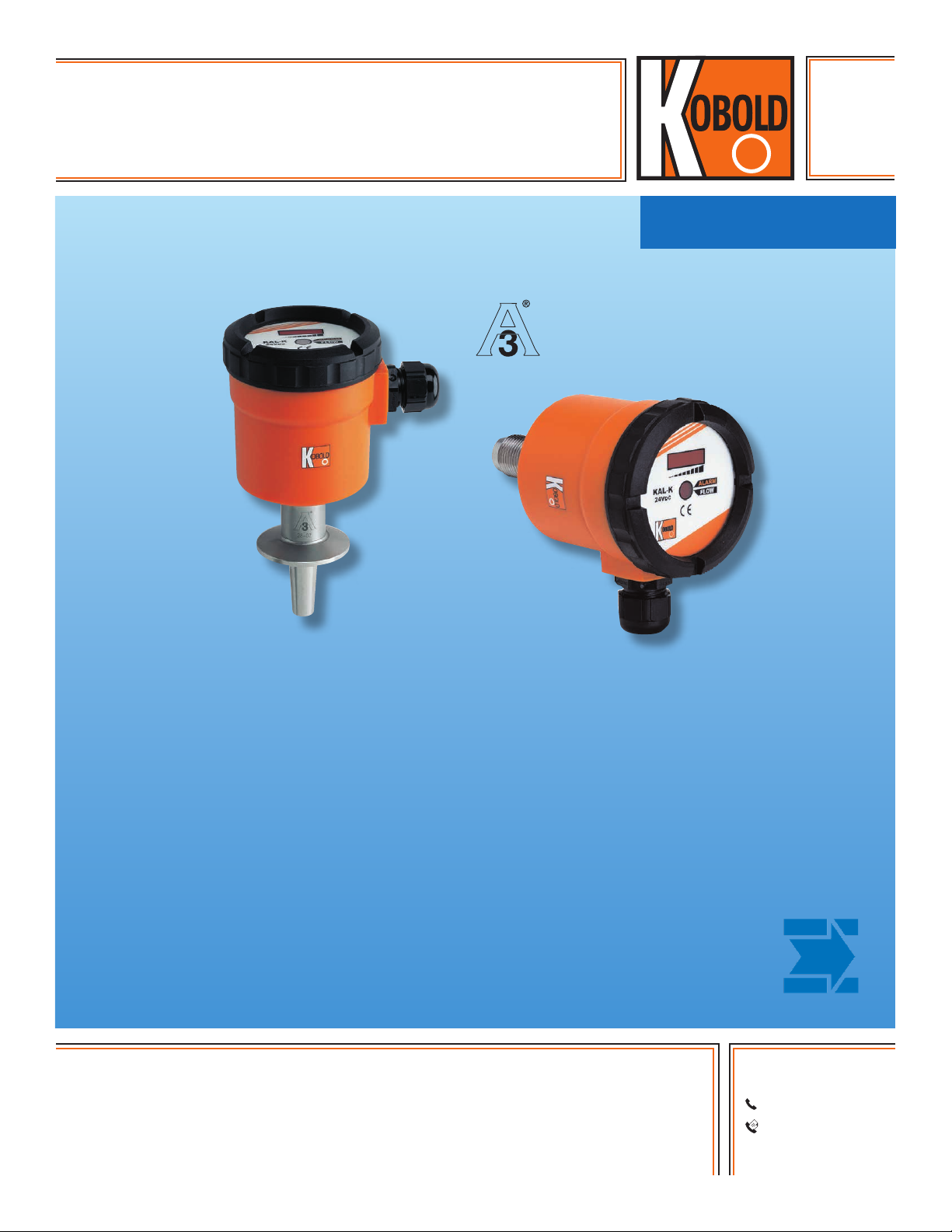
Thermal Flow Switch
for Water-Based Liquids
measuring
•
monitoring
•
analyzing
KAL-K
• Flow Velocities from 0.04...2 m/s
• T
: 250 °F, P
max
: 1450 PSIG
max
• NPT and 3-A Compliant Sanitary Fittings
• No Moving Parts
• Intelligent Temperature Compensation
• Extremely Low Pressure Loss
• Easy to Operate
• Insensitive to Dirt
KOBOLD companies worldwide:
ARGENTINA, AUSTRALIA, AUSTRIA, BELGIUM, BULGARIA, CANADA, CHILE, CHINA, COLOMBIA,
CZECH REPUBLIC, EGYPT, FRANCE, GERMANY, HUNGARY, INDIA, INDONESIA, ITALY, MALAYSIA,
MEXICO, NETHERLANDS, PERU, POLAND, REPUBLIC OF KOREA, ROMANIA, SINGAPORE, SPAIN,
SWITZERLAND, TAIWAN, THAILAND, TUNISIA, TURKEY, UNITED KINGDOM, USA, VIETNAM
05/07-15-2019
KOBOLD Instruments, Inc.
1801 Parkway View Drive
Pittsburgh, PA 15205
Main Ofce:
1.800.998.1020
1.412.788.4890
info@koboldusa.com
www.koboldusa.com
Page 2
Temperatur (C)
0
80
2
Thermal Flow Switch Model KAL-K
Description
The KAL-K thermal flow switch utilizes KOBOLD’s temperature
compensating electronics. This compact, one-piece unit
provides reliable readings unaffected by temperature or physical
characteristics of non-viscous water-based liquids. This is made
possible through the use of state-of-the-art microprocessor
technology. The microprocessor can be field calibrated to both
the liquid properties and operating range in a simple, five minute
set-up procedure. This intelligence, coupled with a “no moving
parts” design, make the KAL a superior performer in virtually all
applications. The KAL-K is also offered in a 3-A compliant version.
The KAL-K incorporates an 8 segment bar-graph LED flow
trend indicator and one flow alarm setpoint. The setpoint is fully
configurable as NPN, PNP, normally open or normally closed.
Operation
The KAL design is based on the time proven calorimetric
principle. The sensor is internally heated to a few degrees above
the temperature of the media. Flow causes removal of heat from
the sensor, resulting in a cooling effect. The rate of cooling is a
measure of the flow velocity. The microprocessor based design
of the KAL distinguishes it from the competition. Full temperature
compensation of the flow rate is readily obtained through a simple,
one-time, calibration procedure. This assures elimination of flow
rate reading drift caused by temperature variations in the process
liquid.
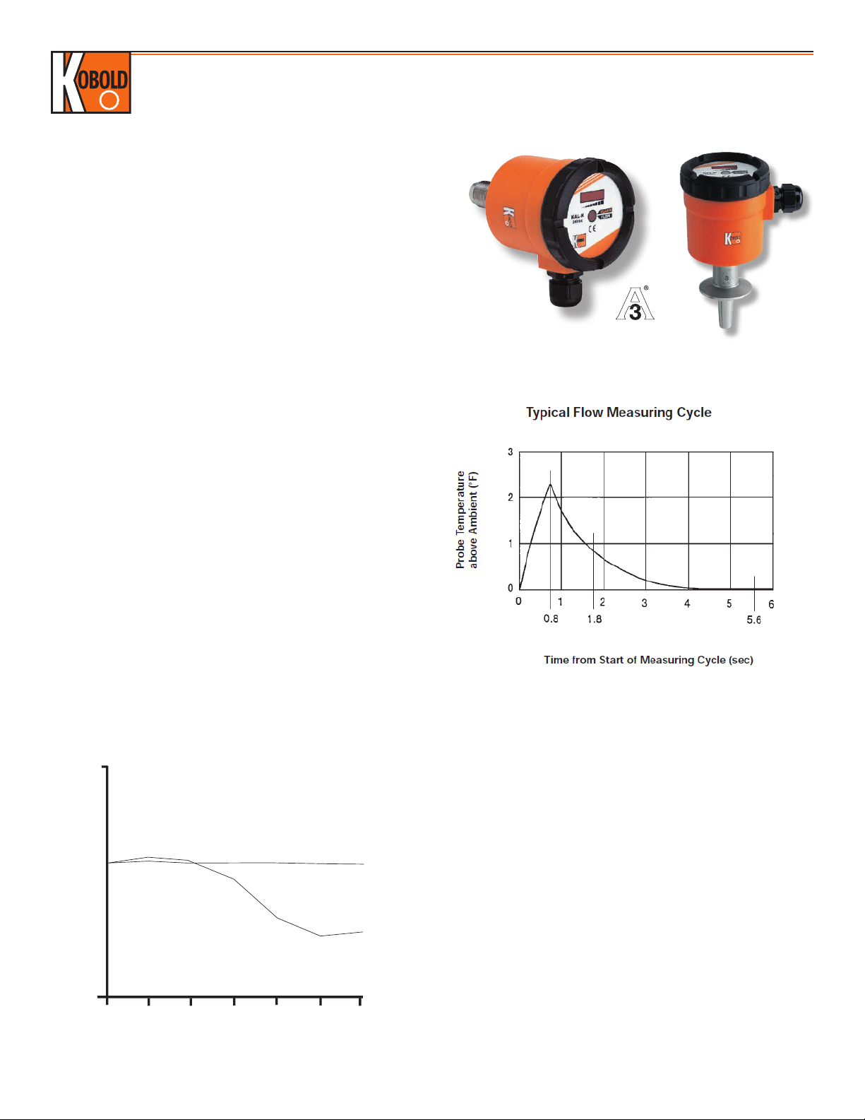
KAL Timing - Heating and Measuring Cycle
Temperature Compensation
The KOBOLD KAL flow products use a microprocessor to
compensate for temperature changes through use of an internal
look-up table. End-users can easily adapt the equipment to the
requirements of their unique installations. Unlike conventional
calorimetric flow switches, the technically advanced design of the
KAL provides a flow reading which is unaffected by temperature.
Operating Behavior
1. At t=0, the probe temperature is recorded. This reading
represents the ambient liquid temperature.
Schaltpunktveränderung über Temperatur
2. Still at t=0, the KAL begins heating the probe.
3. At t=0.8 seconds, the heating cycle ends and the KAL begins
monitoring the probe temperature.
KAL-... with compensation
KAL-... mit Kompensation
4. At t=1.8 seconds, a temperature reading is taken and
compared to the t=0.8 second temperature. The rate of cooling
Schaltpunkt (m/s)
Switch point (m/s)
Standard without
Herkömmlich
compensation
ohne Kompensation
is calculated and compared to a Cooling Rate vs Flow Rate
table specific to the ambient temperature recorded at t=0.
5. The probe is allowed to cool until t=5.6 seconds. A
temperature reading is taken and compared to the initial t=0
reading. If the temperatures are equal (or nearly so), the flow
reading is determined valid and passes through to the KAL
output. If the temperatures are not equal, the KAL waits
20 30
40
Temperature °C
50
60
70
another 5.6 sec, and Step 5 repeats.
2
www.koboldusa.com
No responsibility taken for errors;
subject to change without prior notice.
Page 3

Thermal Flow Switch Model KAL-K
Specifications
Switching Range: 0.04...2 m/s
Media: Water-Based Liquids (Water
Content at least 90%);
not Suitable for Oils or Fuels
Response Time
Typical: 5.6 seconds
Optional w/"F": 1.2 seconds
Fittings
Standard: 1/2" or 3/4" NPT
Sanitary: 1-1/2" Tri-Clamp®
Flow Trend Indicator: 8 Red LEDs
Temperature Rating
Operating: 32...250 °F
CIP: 280 °F (non-operating)
Maximum Pressure
Threaded: 1450 PSIG
Approximate Switch Points at Various Pipe Diameters
Sanitary: 600 PSIG or per Clamp Rating
Wetted Parts
Standard NPT: 304 SS
Optional NPT: 316-Ti SS
Sanitary: 316L SS
Housing
Standard: IP 65
Sanitary: IP 65
Power Requirements
Supply Voltage: 24 VDC ± 10%
Optional: 110 V
Current Draw: 300 mA Max.
AC
Switch Characteristics
Adjustment: By Potentiometer
Status Indicator: Bi-colored LED
24 VDC Units
Type: PNP or NPN, Open Collector
Switch Rating
DC Only: 400 mA at 24V
110 VAC Units:
Type: N/O Dry Contact
Switch Rating
AC Only: 5A at 240 V
Nominal ID
(inch)
1/2 0.08...4.0
3/4 0.2...9.0
1 0.4...16
1 1/4 0.5...25
1 1/2 0.8...36
2 1.3...64
2 1/2 2.0...100
3 3.0...140
Note:
The approximate flow ranges specified in the table above have
been calculated for each pipe diameter from the known flow
velocity range of the KAL. It must be noted that flow in pipes is
non-uniform across the pipe cross-section and approaches zero at
the pipe wall. This means that, in practice, the depth of installation
of the probe, the internal pipe diameter, and the flow profile of the
liquid in the pipe can interact to produce very significant deviations
from the flow ranges in this data sheet.
Range Water
(GPM)
Nominal ID
Range Water
(inch)
4 6.0...250
6 12...575
8 20...1025
10 35...1600
12 50...2300
16 85...4100
20 130...6400
(GPM)
DC Only: 0.2 A at 110V
For correct operation of the KAL-K thermal flow switch, the tip of the flow sensor must be located sufficiently into the flow stream of the
process to sense the liquid flow. Therefore it is very important to consider the sensor's insertion depth and how it is installed in the process
pipe. If the sensor tip is not adequately immersed into the flow stream, the sensor will not measure flow rate correctly, or worst case will not
detect any flow at all. Ideally for correct detection, we recommend the sensor tip be located at a distance from the pipe wall equal to 20% of
the internal cross-section diameter of the pipe. Note that NPT fittings are tapered, and consideration should be given to the fact that when
installed together, NPT mating fittings will not fully thread down to the bottom of the female connection.
KAL-K Order Details (Example: KAL-4315C)
Fitting
Model
(304 SS)
Model
(316-Ti SS)
1/2" NPT KAL-4215 KAL-4315 -
3/4" NPT - KAL-4320 -
1-1/2"
Tri-Clamp®
- - KAL-4340S
*specify probe length on your order (NPT models only)
No responsibility taken for errors;
subject to change without prior notice.
Model
(316 L SS)
www.koboldusa.com
Options
..C = 1/2" NPT Conduit Electrical Connection
..EP = Extended Probe*
..F = Fast Response Time (24 VDC Units Only)
..K = N/C Switch Logic
..M12 = Plug Connector w/6 ft Cable for 24 VDC Units
..P03R = 110 VAC Version with Dry Contact
3
Page 4

Dimensions
Standard Version
Thermal Flow Switch Model KAL-K
1/2" Model
3/4" Model
Sanitary Version
4
www.koboldusa.com
No responsibility taken for errors;
subject to change without prior notice.
 Loading...