

Page 1
KOBOLD KAL-L (KAL-8000 Series)
Thermal Air Flow Switch
User Instructions
KOBOLD Instruments Inc. 1801 Parkway View Drive Pittsburgh PA 15205
Phone (412) 788-2830 • Fax (412)-788-4890
Manual-KAL-L_5-12
Page 2

Page 3

KAL-L
Table Of Contents
1.0 General .......................................................................................................1
2.0 Specifications..............................................................................................1
3.0 Mechanical Installation................................................................................3
3.1 Installation General ..........................................................................3
3.2 Installation of Units with NPT Thread Connection............................5
3.3 Installation of Units with HVAC Flange Connection..........................5
4.0 Electrical Connections ................................................................................5
5.0 Operation ....................................................................................................6
5.1 Flow Setpoint Adjustment ................................................................ 6
5.2 Adjustment of the Start-up Time Delay ............................................8
6.0 Maintenance ............................................................................................... 9
7.0 Need Help with Your KAL-L Flow Switch? ..................................................9
List of Diagrams
Diagram 2.1: Dimensions............................................................................2
Diagram 3.1: General Installation ............................................................... 4
Diagram 3.2: Required Straight Pipe Runs.................................................4
Diagram 4.1: Electrical Connections...........................................................5
Diagram 5.1: Interior Controls Layout for the KAL-L...................................6
List of Tables
Table 2.1: Model Number Codes ........................................................... 3
FM Rev. 5/17/12
Page 4

Page 5

KAL-L
CAUTION: For safety reasons, please read the cautionary information located at
the end of the manual, before attempting installation.
1.0 General
The KAL-L (KAL-8000 Series) Thermal Air Flow Switch uses the proven calorimetric
principle to monitor the flow of air or non-hazardous gases. A sensing resistive thermal
device (RTD) is heated to a few degrees above the temperature of the flow medium. As
the medium flows across the sensing RTD it cools the RTD. The rate of cooling is
proportional to flowrate. A second RTD measures medium temperature and the KAL-L
electronics uses this measurement to compensate for changes in medium temperatures
thus preventing false readings due to medium temperature transients. If the measured
flow value drops below the setpoint value, an output relay is activated providing an alarm
or control input.
2.0 Specifications
Switching Range: 3.3 to 66 feet/second @ 68°F/14.5 PSIA
Restricted span for other pressure and
temperature conditions
Accuracy: ±10% of flow rate
Repeatability: ±1% of flow rate
Display
Flowrate: 8 LED trend indicator
Switchpoint: Flashing LED in trend indicator
Switch Status: Dual colored LED
RED = Flow below switchpoint
GREEN = Flow above switchpoint
Max. Temperature Gradient: 30°K(°C)/Min. @ 25 feet/sec and 190°F
Response Time: Adjustable 1 to 60 seconds
Warm-up Time: 30 seconds
Max. Pressure: 120 PSIG
Temperature Range
Process: -10 to +250°F
Ambient: +15 to +140°F
Wetted Parts: Ni-Plated brass
Housing: Polyamide
Electrical Data
Power Requirements: 24 VDC/VAC +10%/-15%
Switch Characteristics: 1-SPDT relay Max. 250 VAC/4 A/1000
VA
Electrical Connection
Standard: Cable gland
Optional: 1/2” NPT Conduit or M-12 plug
Protection: NEMA 4/IP 65
FM Rev. 5/17/12
Page 6
KAL-L 2
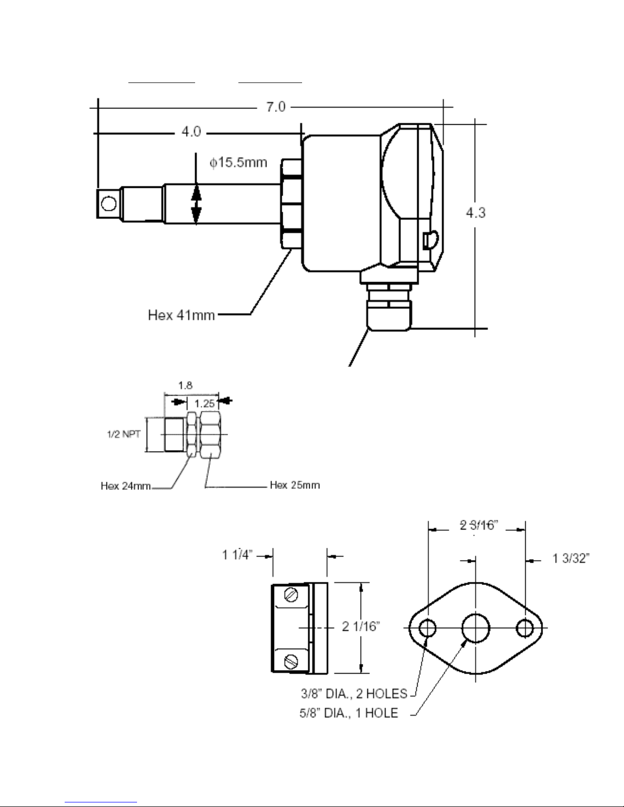
Diagram 2.1 Dimensions
7.0
4.0
φ15.5mm
Hex 41mm
4.3
HVAC Duct Mount
Flange
PG 13.5
Cable Gland
1/2” NPT
Compression Fitting
FM Rev. 5/17/12
All dimensions in inches
Unless otherwise noted
Page 7

3 KAL-L
Table 2.1 Model Number Codes
Model Code Description
KAL-8115 15mm smooth bore probe with 1/2” NPT compression fitting
KAL-8115FL 15mm diameter probe with clamping flange per DIN 43 743
Options
Option Suffix Description
-M12 NEMA 4 electrical plug connector
-C 1/2” NPT conduit connection
3.0 Mechanical Installation
CAUTION
Prior to mechanical installation, ensure that the process flow velocity to be monitored is
within the switching range of the device. Also ensure that system temperature and
pressure are within the limit of the device. See Section 2.0 ”Specifications”.
3.1 Installation General
The following general installation instructions and precautions apply to all KAL-8000
series installations:
3.1.1 The probe tip must be inserted a minimum of 3/8” beyond the
inside diameter of the pipe or duct into which it is to be installed.
Best results are obtained if the probe is inserted into the pipe or duct 1/
2” or greater.
3.1.2 In order to ensure that the sensing elements are facing directly into the
flow stream, a notch has been placed on the probe hex nut to aid in
alignment. For optimal results, the probe should be installed so that the
notch is aligned directly over the centerline of the pipe or duct.
3.1.3 In order to ensure a uniform flow profile across the probe tip, install the
probe to allow for 10 pipe diameters of straight run piping upstream and
5 downstream. This piping should be free of tees, elbows, bends,
valves, dampers or any other such appurtenances.
3.1.4 The probe should not be installed in the lower hemisphere of the pipe or
duct. Liquid and debris which collect in the lower portion of the pipe will
cause the probe to function erratically if they come in contact with the
probe.
FM Rev. 5/17/12
Page 8

KAL-L 4
Diagram 3.1 General Installation
3/8” Min. probe
insertion depth.
1/2” or greater is
optimal
Liquid and sediment
which settle at the bottom
cannot cause measuring
errors
Mount the unit
in the pipe upper
hemisphere
C
L
Mount probe such that
the notch cut into the
hex is perpendicular to
the pipe centerline to
ensure that the probe is
properly oriented in the
flow stream.
Diagram 3.2 Required Straight Pipe Runs
10XD Upstream
5XD Downstream
Flow
3.2 Installation of Units with NPT Thread Connection
FM Rev. 5/17/12
Page 9

5 KAL-L
3.2.1 Units with NPT threaded connections are best suited for round pipes or
ducts in which systems are under pressure. The NPT connection
makes a leaktight seal to 120 PSIG.
3.2.2 The threaded connection should be installed into a pipe via a 1/2” weld
coupling or a pipe tee with 1/2” connection. If a bushing is used to
reduce a larger fitting size to 1/2”, ensure that the probe insertion
requirements are met. See Section 3.1 ”Installation General”.
3.2.3 Ensure that a thread sealant such as PTFE tape is used to seal the
threads.
3.3 Installation of Units with HVAC Flange Connection
3.3.1 Units with flanged connections are best suited for square ducts in HVAC
applications where adding an NPT connection is impractical.
3.3.2 Prior to installing the flange, the flange face which contacts the surface
of the HVAC duct should be sealed using a field manufactured gasket
or RTV compound. This will minimize leakage at the flange face.
4.0 Electrical Connections
4.0.1 All electrical connections are made at the terminal blocks inside the
electronics enclosure of the KAL-L.
4.0.2 The KAL-L can operate using a power supply of 24 VAC or DC. When
DC voltage is used, the input supply is non-polarized. The polarity
of the DC input voltage does not matter and can be wired in either
direction without affecting the operation of the unit.
Diagram 4.1 Electrical Connections
Relay Output
SPDT
Max. 4A @ 250 VAC
FM Rev. 5/17/12
Page 10

KAL-L 6
5.0 Operation
Diagram 5.1 Interior Controls Layout for the KAL-L
Setpoint LED
Fixed at 3rd LED
(flashing)
Trend Indicator
8 LEDs
Span Adjustment P1
DUO-LED
Green= Flow > Setpoint
Relay Activated
Red = Flow < Setpoint
Relay Deactivated
RELAY
24V AC/DC
Start-up Time Delay P2
Holds the relay in activated
state for 0 to 60 seconds after
power-up
5.1 Flow Setpoint Adjustment
The section describes the procedures for adjustment of the flow setpoint for three
scenarios:
• Adjustment of precise setpoint on falling flow.
• Adjustment of precise setpoint on rising flow.
• Setup for flow/no flow detection.
5.1.1
Flow Setpoint Adjustment - General
The flow switch point on the KAL-L is fixed at 50% of its span. Because of the trend
indicator’s non-linear response, this corresponds to the third LED on the indicator bar.
The third LED is wired to flash permanently to allow users to judge the location of the
flow setpoint relative to system flow.
The flow switch point is set by adjusting the span potentiometer P1. Doing this increases
or decreases the span of the trend indicator thereby changing the point at which the
KAL-L switches. The next three sections describe how to set the KAL-L switchpoint in
specific situations
FM Rev. 5/17/12
Page 11

7 KAL-L
5.1.2 Adjustment of Precise Setpoint on Falling Flow
To adjust the KAL-L for a precise switchpoint on falling flow, refer to Diagram 5.1 on page
6 and proceed as follows:
5.1.2.1 With power connected to the KAL-L, adjust the span potentiometer P1 clockwise to its right hand stop.Turn time delay potentiometer P2 counter-clockwise to its far lefthand stop.
5.1.2.2 Initiate system flow and adjust it to the desired switchpoint flow
rate. Note that at this time the DUO LED should be green. If it is
red your desired flowrate is below the measuring capability of the
KAL-L.
5.1.2.3 Slowly turn P1 counter-clockwise. You will note that the LEDs on
the trend indicator will extinguish sequentially as the span is
reduced. Continue turning P1 counter-clockwise until the trend
indicator span is reduced to the third LED (which is flashing). At
this point, the DUO-LED turns red and the relay switches over.
The KAL-L is now adjusted at the desired setpoint.
5.1.2.4 Adjust system flow to normal.
5.1.3 Adjustment of Precise Setpoint on Rising Flow
To adjust the KAL-L for a precise switchpoint on rising flow, refer to Diagram 5.1 on page
6 and proceed as follows:
5.1.3.1 With power connected to the KAL-L, adjust the span potentiometer P1 counter-clockwise to its left hand stop. Turn time delay
potentiometer P2 counter-clockwise to its far lefthand stop.
5.1.3.2 Initiate system flow and adjust it to the desired switchpoint flow
rate.
5.1.3.3 Slowly turn P1 clockwise. You will note that the LEDs on the
trend indicator will light sequentially as the span is increased
from zero. Continue turning P1 clockwise until the trend indicator
span is increased to the third LED (which is flashing). At this
point, the DUO-LED turns green and the relay switches over.
The KAL-L is now adjusted at the desired setpoint.
5.1.3.4 Adjust system flow to its normal value.
FM Rev. 5/17/12
Page 12

KAL-L 8
5.1.4 Setup of the KAL for Flow/No-flow Detection
Alternatively, the KAL-L can be quickly set-up to switch on a loss of flow. Using this
procedure does not yield a precise switchpoint but is generally acceptable for flow/noflow detection. When set up in this manner, the KAL-L will switch when approximately a
50% reduction from normal flow occurs. To set the KAL-L for flow/no-flow detection, refer
to Diagram 5.1 and proceed as follows:
5.1.4.1 With power connected to the KAL-L, adjust the span potentiometer P1 counter-clockwise to its left hand stop.Turn time delay
potentiometer P2 counter-clockwise to its far lefthand stop.
5.1.4.2 Initiate system flow. Ensure that system flow rate is at normal
operating value.
5.1.4.3 Slowly turn P1 clockwise. You will note that the LEDs on the
trend indicator will light sequentially as the span is increased
from zero. Continue turning P1 clockwise just until all 8 trend
indicator LEDs are lit. As the trend indicator span is adjusted
past the third LED (which is flashing) note that the DUO LED
changes from red to green and the relay switches over.
5.1.4.4 The KAL-L is now adjusted for flow/no flow detection. The switch
point will occur on a flow rate reduction of approximately 50%
from normal operating value.
5.2 Adjustment of the Start-up Time Delay
The KAL-L has a start-up time delay feature which holds the output relay in the activated
state and disables flow monitoring for a period of up to 60 seconds after power-up of the
KAL-L. This feature is designed to prevent nuisance alarms during system start-up and
until steady state flow conditions are achieved.
To adjust the start-up time delay, refer to Diagram 5.1 on page 6 and proceed as follows:
5.2.1 Potentiometer P2 adjusts the start-up time delay. Turning P2 counterclockwise to its far left hand stop adjusts the time delay to zero. Turning
P2 clockwise increases the time delay to a maximum possible of 60
seconds at the far right hand stop. The time delay adjustment is approximately linear between the left and right hand stops.
FM Rev. 5/17/12
Page 13

9 KAL-L
6.0 Maintenance
The KAL-L is an electronic device which uses no moving parts. This design ensures
reliable operation and long service life. Dirt and debris which can build up on the sensing
probe over time will result in degraded performance. For this reason we strongly
recommend that the proper filtration be installed in the system. It is also recommended
that the KAL-L be occasionally removed from the system and its measuring probe
inspected for dirt buildup and cleaned as needed. The frequency of this cleaning will vary
depending on the cleanliness of the system.
7.0 Need Help with Your KAL-L Flow Switch?
Contact one of our friendly engineers at 412-788-2830.
FM Rev. 5/17/12
Page 14

Page 15

11 KAL-L
CAUTION
PLEASE READ THE FOLLOWING WARNINGS BEFORE ATTEMPTING
INSTALLATION OF YOUR NEW DEVICE. FAILURE TO HEED THE
INFORMATION HEREIN MAY RESULT IN EQUIPMENT FAILURE AND
POSSIBLE SUBSEQUENT PERSONAL INJURY.
FM Rev. 5/17/12
Page 16

KAL-L 12
• User's Responsibility for Safety: KOBOLD manufactures a wide range of
process sensors and technologies. While each of these technologies are
designed to operate in a wide variety of applications, it is the user's
responsibility to select a technology that is appropriate for the application,
to install it per these installation instructions, to perform tests of the
installed system, and to maintain all components. The failure to do so could
result in property damage or serious injury.
• Proper Installation and Handling: Use a proper sealant with all
installations. Never overtighten the unit within the fitting. Never use the
housing to thread the unit into its fitting. Always use only an
appropriate sized wrench on the hex portion of the probe. Always check for
leaks prior to system start-up.
• Wiring and Electrical: A supply voltage of 24 Volts AC or DC +10%/-15%
is used to power the KAL-L. The sensor systems should never exceed this
rating. Electrical wiring of the sensor should be performed in accordance
with all applicable national, state, and local codes.
• Temperature and Pressure: The KAL-K is designed for use in application
temperatures from -10 to 250°F, and for use at pressures up to 115 PSIG.
Operation outside these limitations will cause damage to the unit and
possible personal injury.
• Material Compatibility: The KAL-K sensor probe is made of nickel plated
brass. The housing is polycarbonate. Check your model number with the
wetted materials specification in Section 2.0 ‚"Specifications”, on page 1 of
this manual. Make sure that the model which you have selected is
chemically compatible with the application environment. While the switch
housing is liquid resistant when installed properly, it is not designed to be
immersed. It should be mounted in such a way that it does not normally
come into contact with liquid.
• Flammable, Explosive and Hazardous Applications: The KAL-L is not
an explosion-proof or intrinsically safe design. It should not be used in
hazardous areas where risk of explosion exists.
• Make a Fail-safe System: Design a fail-safe system that accommodates
the possibility of switch or power failure as well as operator error. In critical
applications, KOBOLD recommends the use of redundant backup systems
and alarms in addition to the primary system.
FM Rev. 5/17/12
Page 17

Page 18

 Loading...