

Page 1
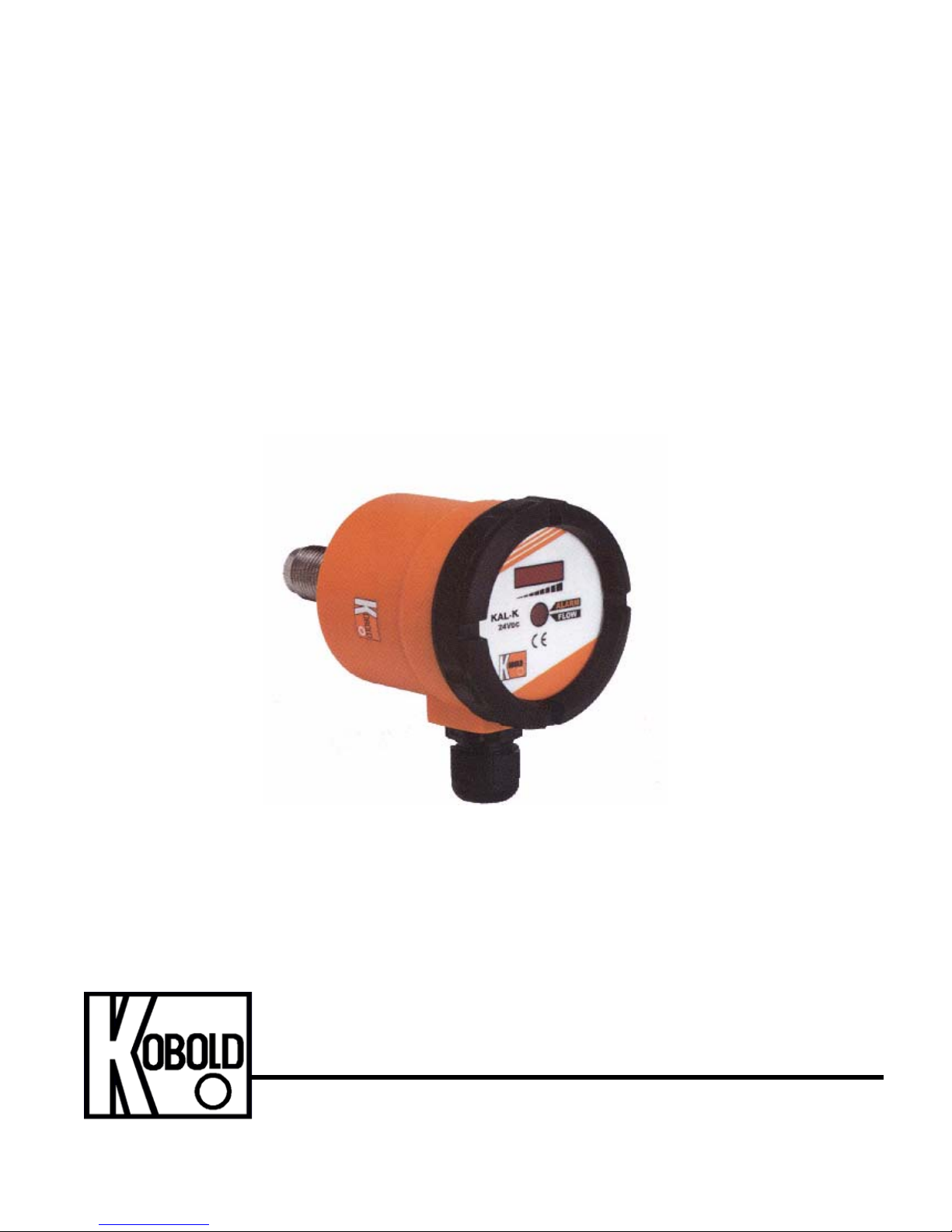
KOBOLD KAL-K (KAL-4000 Series)
Thermal Flow Switch
User Instructions
KOBOLD Instruments Inc. 1801 Parkway View Drive Pittsburgh PA 15205
Phone (412) 788-2830 • Fax (412)-788-4890
KAL-K_manual_8-29-06
Page 2

Page 3

KAL-K
Table of Contents
1.0 General............................................................................................. 1
2.0 Specifications................................................................................... 1
3.0 Mechanical Installation...................................................................... 4
4.0 Electrical Connections...................................................................... 5
5.0 Operation.......................................................................................... 7
5.1 Calibration............................................................................. 7
5.2 Flow Setpoint Adjustment...................................................... 8
5.3 Setting the KAL-K Output Transistor Type............................ 9
5.4 KAL-K Diagnostics and Troubleshooting.............................. 9
5.5 Applications........................................................................... 10
6.0 Maintenance..................................................................................... 11
7.0 Arrival of Damaged Equipment........................................................ 11
8.0 Need Help With Your KAL-K............................................................ 11
List of Diagrams
Diagram 2.1 Dimensions................................................................ 3
Diagram 3.1 Mechanical Installation............................................... 4
Diagram 4.1 Interior Controls Layout for 24 VDC Versions............ 5
Diagram 4.2 Interior Controls Layout for 110 VAC Versions........... 5
Diagram 4.3 KAL-K Wiring 24 VDC Versions................................. 6
Diagram 4.4 KAK-K Wiring 110 VAC Versions............................... 6
Diagram 4.5 Quick Disconnect (option M-12) Wiring 7
List of Tables
Table 2.1 Switching Ranges Vs. Pipe Diameter.......................... 2
FM Rev. 8/29/06
Page 4

Page 5

KAL-K
CAUTION: For safety reasons, please read the cautionary information located at
the end of the manual, before attempting installation.
1.0 General
The KOBOLD KAL-K (a.k.a. KAL-4000 Series) flow switch is intended for use in
monitoring and control applications involving moderate flowrates of non-viscous or dirty
liquids. The KAL-K flow switch uses the proven thermal dispersion principle and operates
as follows:
1. The probe is heated internally to a few degrees above the temperature of the
medium into which it extends.
2. As the medium flows past the probe it removes heat from the probe tip. The
rate at which heat is removed is proportional to the flowrate.
3. The measured flowrate is compared to the setpoint value selected by the user.
If the setpoint is reached, the electronic circuitry activates a transistor switch
and bi-colored alarm LED. The electronic circuitry also controls an LED trend
indicator which can be used to indicate relative system flow.
The microprocessor-controlled design permits simple calibration and setup. The compact
probe design permits monitoring of flowrate with minimal head loss.
2.0 Specifications
Measuring Range: 0.05 - 2 meters/sec.
Available Fitting Sizes: 1/2” NPT
1-1/2” Tri-Clamp®
3/4” NPT
Maximum Pressure: 1450 PSIG for threaded units,
Tri-Clamp® versions to clamp rating
Maximum Temperature:
Ambient: 0 to 140°F
Medium: 32° to 250°F
Clean in Place (CIP): 280°F (non-operating)
Supply Power:
Standard: 24 VDC ± 10%, 300 mA Max.
Optional: 110 VAC Nominal
Wetted Parts:
KAL-4215: 304 Stainless Steel
KAL-4315: 316 Stainless Steel
KAL-4320: 316 Stainless Steel
KAL-4340-S 316 Stainless Steel
FM Rev. 8/29/06
Page 6

KAL-K 2
Housing: Reinforced Polyamide (NEMA 4)
Switching Characteristics:
Switchpoint Adjustment: By internal potentiometer
Switch Type:
Standard: NPN or PNP transistor (selectable)
Suffix P03R: SPST relay, 5 A @ 250 VAC Max.
Calibration Data: Stored in non-volatile memory, data
Table 2.1 Switching Ranges Vs. Pipe Diameter
Max. 24 VDC, 400mA
retained for at least 10 years in the event
of power failure
Nominal I.D
Inches
Range
GPM Water
Nominal I.D
Inches
Range
GPM Water
1/2 0.3-5.0 4 12-220
3/4 0.5-8.9 6 28-500
1 0.8-14 8 50-900
1-1/4 1.1-20 10 78-1400
1-1/2 2.0-35 12 110-2000
2 3.1-55 16 200-3600
3 7.9-140 20 310-5600
Note: The flow ranges specified in the table above have been calculated for each pipe diameter
based on the known velocity range of the KAL-K. It must be noted that flow in pipes is
non-uniform across the pipe cross section, and approaches zero at the pipe wall. This
means that, in practice, the depth of installation of the probe, the internal pipe diameter,
and the flow profile of the liquid in the pipe can interact to produce significant deviations
from the flow ranges in the above table.
FM Rev. 8/29/06
Page 7

Diagram 2.1 Dimensions
KAL-4215, 4315, 4320
3 KAL-K
KAL-4340S
FM Rev. 8/29/06
Page 8

KAL-K 4
3.0 Mechanical Installation
To install the KAL-K flow switch into your piping system, proceed as follows:
3.0.1 The KAL-K flow switch can be mounted in virtually any orientation
as long as the piping is completely filled with fluid. It is recommended that the unit be installed in the upper hemisphere of the
pipe when being used in horizontal piping runs. This ensures that
sediments do not deposit on the probe. It is also recommended that
the unit not be installed in the top of the pipe on horizontal runs. This
ensures that air pockets which collect in the top of the pipe do not
cause false switching
Diagram 3.1 Mechanical Installation
Incorrect
Correct
Bubbles can insulate the
probe from the process liquid
Sediments cannot
on the probe collect
3.0.2 For optimal measuring accuracy, allow for a minimum of 5 pipe
diameters of straight-run piping both upstream and downstream of
the flow switch. This ensures that flow profile at the sensing probe is
uniform and fully developed.
3.0.3 Prior to installation, ensure that the desired flow alarm setpoint is
within the switching range of the KAL-K. Additionally, ensure that the
maximum system temperature and pressure are within the limits
specified per Section 2.0, Specifications.
3.0.4 It is recommended that a suitable thread sealant, such as PTFE
tape, be applied to the probe threads to ensure a leaktight seal.
3.0.5 Using an appropriate sized wrench, carefully thread the sensor
probe into the piping system. The probe must be installed such that,
at a minimum, the probe tip extends beyond the inner diameter of
the piping and into the fluid stream.
FM Rev. 8/29/06
Page 9

5 KAL-K
4.0 Electrical Connections
Diagram 4.1 shows the layout of electrical connections, as well as other controls for the
24 VDC KAL-K. Diagram 4.2 shows the layout for 110 VAC versions.
Diagram 4.1
Output Selector
Switch SW2
PNP/NPN
Setpoint
Potentiometer P1
Terminal Strip
3=+24 VDC
2=DC Ground
1=Output
Diagram 4.2 Interior Controls Layout for 110 VAC Versions
Interior Controls Layout for 24VDC Versions
Trend Indicator
(8 LED’s)
Calibrating
Switch SW 1
3
2
1
Bi-colored LED
Green = Switch Activated
Red = Switch not Activated
trend indicator LED’s
bi-colored LED
setpoint potentiometer P1
access
calibrating switch SW1
access
FM Rev. 8/29/06
Page 10

KAL-K 6
Diagram 4.3 shows typical electrical wiring for the KAL-K 24 VDC versions configured as
either a NPN or PNP transistor switch. Instructions for selecting between the PNP or
NPN output is provided in section 5.3, Setting the KAL-K Output Type. The KAL-K
requires a 24 VDC, 300 mA power supply regulated to within ±10%. If the same power
supply will be used to provide current to devices being switched by the KAL-K (e.g.
relays), sufficient additional current must be available to power these devices. Diagram
4.4 shows the wiring for the 110 VAC versions of the KAL-K (suffix P03R).
Diagram 4.3 KAL-K Wiring 24 VDC Versions
NPN Configuration
-DC Ground switched to pin 1 when switch
is activated. High impedance at pin 1 when
switch is not activated.
KAL-K
PNP
NPN
24 VDC
+
300 mA
L
+
O
-
A
SW 1
3
2
1
3=24 VDC
2=GND
1=Output
D
-
Diagram 4.4 KAL-K Wiring 110 VAC Versions
PNP Configuration
+24 VDC is switched to pin 1 when switch
is activated. High impedance at pin 1 when
switch is not activated.
KAL-K
NPN
PNP
SW 1
3
2
1
3=24 VDC
2=GND
1=Output
24 VDC
+
300 mA
L
O
A
D
-
+
-
FM Rev. 8/29/06
1
Switch: 250 VAC @5 Amp
2
3
110 VAC Power
4
Green/Yel = Ground
Page 11

7 KAL-K
Diagram 4.5 Quick Disconnect (option M-12) wiring
24 VDC Version
2
3
1 = Brown = + 24 VDC
2 = White = Switch Output
3 = Blue =
4 = Black = Switch Output
1
4
- DC Common (Ground)
5.0 Operation
This section will provide details on the following aspects of KAL-K operation:
• Calibration of the zero-flow reference and trend indicator span.
• Adjustment of the flow switch setpoint.
• Transistor output type selection.
• Computer self-monitoring diagnostic routine within the KAL-K software.
5.1 Calibration
5.1.1 Zero Flow Calibration
Calibration of the KAL-K electronics at zero system flow is necessary in order to obtain
optimal performance from your KAL-K. This procedure is used to store data pertaining to
the thermal characteristics of the fluid being monitored.
To perform the zero flow alignment, refer to Diagram 4.1 for 24 VDC versions, and
Diagram 4.2 for 110 VAC versions. Proceed as follows:
5.1.1.1 Ensure that the fluid system is in a no-flow condition.
5.1.1.2 Ensure that the system is completely filled and that the KAL-K
sensing probe is completely immersed in fluid.
5.1.1.3 With power connected to the unit, turn setpoint adjustment
potentiometer P1 counterclockwise to its far lefthand stop.
5.1.1.4 Momentarily depress the calibrating switch SW1 and release.
The bi-colored LED will flash green for a brief period while the
unit is zeroing.
Note: Do not adjust the setpoint potentiometer P1 while the bi-colored
LED is flashing. Doing this will invalidate the zero calibration and
the procedure will have to be repeated.
5.1.1.5 When the bi-colored LED stops flashing, the zero flow calibration
is complete.
FM Rev. 8/29/06
Page 12

KAL-K 8
5.1.2 Adjustment of the Trend Indicator Span
The KAL-K is factory preset at its maximum possible span. This span corresponds to a water
flow velocity of 2 meters/second. This flow velocity will result in the illumination of all eight flow
trend indicator LED’s. If the flow velocity in your system is significantly less than 2 meters/
second, only two or three of the trend indicator LED’s may be lit during normal operation. The
trend indicator span can be adjusted so that maximum system flow will result in a full span
deflection of the flow trend indicator LED’s, thereby improving resolution.
To adjust the trend indicator span, refer to Diagram 4.1 for 24 VDC versions, and Diagram 4.2
for 110 VAC versions. Proceed as follows:
5.1.2.1 With the system completely filled, adjust flow to its maximum value.
5.1.2.2 With power applied to the KAL-K, turn the setpoint potentiometer P1
clockwise to its far right-hand stop. The far right LED on the trend
indicator will be flashing.
5.1.2.3 Momentarily depress the calibrating switch SW1 and release. The bicolored LED will flash green for a brief period while the unit selfadjusts the span.
Note: Do not adjust the setpoint potentiometer P1 while the bi- colored LED
is flashing. Doing this will invalidate the span adjustment and the
procedure will have to be repeated.
5.1.2.4 When the bi-colored LED stops flashing, the span adjustment is
complete. One measuring cycle after the bi-colored LED stops
flashing (approximately 10 seconds) all, or nearly all eight of the trend
indicator LED’s should be lit.
5.2
Flow Setpoint adjustment
To adjust the flow setpoint on the KAL-K, refer to Diagram 4.1 for 24 VDC versions, and
Diagram 4.2 for 110 VAC versions. Proceed as follows:
5.2.0.1 Adjust system flow to the value at which the setpoint is desired.
5.2.0.2 Potentiometer P1 adjusts the flow setpoint. the flashing LED on the
trend indicator signifies the switch point. You will notice that the
flashing LED moves along the trend indicator scale as potentiometer
P1 is adjusted.
5.2.0.3 With system flow adjusted to the desired value, adjust potentiometer
5.2.0.4 The KAL-K flow setpoint is now adjusted and system flow can be
FM Rev. 8/29/06
P1 until the KAL-K output switches state and the bi-colored LED
changes color.
restored to normal.
Page 13

9 KAL-K
5.3 Setting the KAL-K Output Transistor Type (24 VDC versions Only)
The KAL-K is shipped from the factory as a normally open (N/O) logic, PNP transistor
output. The transistor output of the KAL-K can be field switched from PNP to NPN if
desired by using SW 2. See Diagram 4.1.
The characteristics of the N/O switch logic, and the PNP and NPN transistor switch
outputs are as follows:
N/O Switch:
System flow above the flow setpoint: Switch = ACTIVATED
Bi-colored LED = GREEN
NPN Switch = Pin 1 SWITCHED TO GROUND
PNP Switch = Pin 1 SWITCHED TO +24VDC
System flow below the flow setpoint: Switch = DE-ACTIVATED
Bi-colored LED = RED
NPN Switch = Pin 1 HIGH RESISTANCE
(open switch)
PNP Switch = Pin 1 HIGH RESISTANCE
(open switch)
5.4 KAL-K Diagnostics and Troubleshooting
The KAL-K continuously self-monitors the sensing probe and micro-processor systems.
Any fault in these portions of the electronics will be signaled by a flashing red bi-colored
LED. Additionally, if any of the calibrations (i.e. zero/span adjustments) are done
improperly, the KAL-K bi-colored LED may flash red indicating that an error in the
calibration procedure may have occurred. If the bi-colored LED starts to flash red at any
time during the calibrating sequence, simply power the unit down for approximately 30
seconds, re-apply power and restart the calibration procedure. If the bi-colored LED
flashes red during normal operation, a fault with the unit may have occurred. Contact
KOBOLD Instruments for assistance.
FM Rev. 8/29/06
Page 14

KAL-K 10
5.5 Applications
5.5.1 Wiring the KAL-K to Activate a Relay
A common application of the transistor type switch is to use it to activate a DC relay. It
may be necessary to use the KAL-K to activate a relay if:
1.It is necessary to switch an AC load (transistor switches only switch DC loads).
2.The DC load to be switched exceeds the current rating of the KAL-K transistor
switch.
3.It is desirable to protect the KAL transistor output from damage by using an
inexpensive relay.
The circuit to the right
demonstrates how a relay should
be connected to the KAL-K. The
relay shown is a Potter &
Brumfield model, but any 24
VDC relay will work as long as
the coil current does not exceed
400 mA. SW 2 should be
switched to the right for an NPN
output. The diode connected
across the relay coil protects the
KAL-K output against voltage
spikes which occur when the
relay activates and deactivates.
PNP
SW 2
KAL-K
NPN
3
2
1
+24VDC
7
1N4003
Diode
2
Potter & Brumfield
KRPA11DY24 or
equivalent relay
DC GND
FM Rev. 8/29/06
Page 15

11 KAL-K
6.0 Maintenance
The KAL-K thermal flow switch is an electronically controlled device with no moving
parts. As a result the unit is virtually maintenance free. Occasional cleaning of the
immersed probe may be required if the fluid media is such that it tends to deposit or build
up a film layer on the probe. If this occurs, the unit should be removed from the system
and any deposits or coatings on the probe should be removed.
7.0
Arrival of Damaged Equipment
Your instrument was inspected prior to shipment and found to be defect-free. If damage
is visible on the unit, we advise that you carefully inspect the packing in which it was
delivered. If damage is visible, notify your local carrier at once. The carrier is liable for a
replacement under these circumstances. If your claim is refused, please contact
KOBOLD Instruments.
8.0
Need Help With Your KAL-K
Call one of our friendly engineers at 412-788-2830
FM Rev. 8/29/06
Page 16

Page 17

13 KAL-K
CAUTION
PLEASE READ THE FOLLOWING WARNINGS BEFORE ATTEMPTING
INSTALLATION OF YOUR NEW DEVICE. FAILURE TO HEED THE
INFORMATION HEREIN MAY RESULT IN EQUIPMENT FAILURE AND
POSSIBLE SUBSEQUENT PERSONAL INJURY.
FM Rev. 8/29/06
Page 18

Page 19

15 KAL-K
• User's Responsibility for Safety: KOBOLD manufactures a wide range of
process sensors and technologies. While each of these technologies are
designed to operate in a wide variety of applications, it is the user's
responsibility to select a technology that is appropriate for the application,
to install it per these installation instructions, to perform tests of the
installed system, and to maintain all components. The failure to do so could
result in property damage or serious injury.
• Proper Installation and Handling: Use a proper sealant with all
installations. Never overtighten the unit within the fitting. Never use the
housing to thread the unit into its fitting. Always use only an
appropriate sized wrench on the hex portion of the probe. Always check for
leaks prior to system startup.
• Wiring and Electrical: Depending on the model, a supply voltage of 24
VDC ±10% or 110 VAC is used to power the KAL-K. The sensor systems
should never exceed this rating. Electrical wiring of the sensor should be
performed in accordance with all applicable national, state, and local
codes.
• Temperature and Pressure: The KAL-K is designed for use in application
temperatures from 0° to 250°F, and for use at pressures up to 1450 PSIG
for threaded probes. Tri-Clamp® probes are rated to the pressure rating of
the user supplied clamp. Operation outside these limitations will cause
damage to the unit and possible personnel injury.
• Material Compatibility: The KAL-K sensor probe is made of either 304 or
316 stainless steel. The housing is constructed of polyamide. Check your
model number with the wetted materials specification in Section
2.0‚"Specifications”, on page 1 of this manual. Make sure that the model
which you have selected is chemically compatible with the application
liquids. While the switch housing is liquid resistant when installed properly,
it is not designed to be immersed. It should be mounted in such a way that
it does not normally come into contact with fluid.
• Flammable, Explosive and Hazardous Applications: KAL models
should not be used in areas where an explosion-proof design is required.
• Make a Fail-Safe System: Design a fail-safe system that accommodates
the possibility of switch or power failure as well as operator error. In critical
applications, KOBOLD recommends the use of redundant backup systems
and alarms in addition to the primary system.
FM Rev. 8/29/06
 Loading...