

Page 1
OPERATING MANUAL HPC & UMC4
Page 1 of 105
Coriolis – Mass-Flow Meter
HPC
UMC4
Operating manual
Please read the instructions carefully and store them in a safe place for future use!
Page 2

Page 2 of 105
OPERATING MANUAL HPC & UMC4
Contents
INTRODUCTION ............................................................................................................ 8
I. Shipping and storage; product inspection ............................................................................................. 8
II. Warranty ................................................................................................................................................ 8
III. Application domain the operating manual ......................................................................................... 8
IV. Measures to be taken before sending your device to the manufacturer for repair ............................ 8
V. Supplementary operating instructions regarding the HART interface ............................................ 8
VI. Operating manual of explosion-proof flow meters ............................................................................. 8
1. STEPS PRIOR TO OPERATION ........................................................................... 9
1.1 Safety advisory for the user ............................................................................................................. 10
1.2 Hazard warnings .............................................................................................................................. 10
1.2.1 Danger ...................................................................................................................................... 10
1.2.2 Warning .................................................................................................................................... 10
1.2.3 Caution ..................................................................................................................................... 10
1.2.4 Note .......................................................................................................................................... 10
1.3 Proper use of the device .................................................................................................................. 11
1.4 Installation and servicing ................................................................................................................. 11
1.5 Returning your flow meter for servicing or calibration ..................................................................... 12
1.6 Replacement of the transmitter electronics ..................................................................................... 12
2. MAINTENANCE .................................................................................................. 13
2.1 Transmitter ....................................................................................................................................... 13
2.2 Coriolis mass flow sensor ................................................................................................................ 13
3. IDENTIFICATION ................................................................................................ 13
4. THE HPC SENSOR ............................................................................................. 14
4.1 Application domain of the HPC sensor ............................................................................................ 14
4.2 Mode of operation ............................................................................................................................ 14
4.2.1 Measuring principle .................................................................................................................. 14
4.2.2 System configuration ................................................................................................................ 14
4.2.3 Measured variables .................................................................................................................. 14
Page 3

OPERATING MANUAL HPC & UMC4
Page 3 of 105
4.3 Performance characteristics of the HPC sensor ............................................................................. 15
4.3.1 Reference conditions ................................................................................................................ 15
4.3.2 HPC flow ranges....................................................................................................................... 15
4.3.3 Density measurement .............................................................................................................. 15
4.3.4 Accuracy ................................................................................................................................... 16
4.3.5 Pressure loss HPC ................................................................................................................... 16
4.3.6 Ambient temperature range ...................................................................................................... 16
4.3.7 Storage temperature ................................................................................................................ 16
4.3.8 Climatic category ...................................................................................................................... 16
4.3.9 Ingress protection ..................................................................................................................... 16
4.4 Operating conditions ........................................................................................................................ 17
4.4.1 Installation ................................................................................................................................ 17
4.4.2 Installation positions ................................................................................................................. 18
4.4.3 Pressure surges ....................................................................................................................... 19
4.4.4 Using the device with hazardous fluids .................................................................................... 20
4.4.5 Vibration stability ...................................................................................................................... 20
4.5 Process conditions ........................................................................................................................... 21
4.5.1 Process temperature ................................................................................................................ 21
4.5.2 Physical state ........................................................................................................................... 21
4.5.3 Viscosity ................................................................................................................................... 21
4.5.4 Gas content .............................................................................................................................. 21
4.5.5 Process temperature range ...................................................................................................... 21
4.5.6 Process pressure range ........................................................................................................... 21
4.5.7 Outlet pressure ......................................................................................................................... 21
4.6 Connection to the transmitter .......................................................................................................... 21
4.7 Construction details ......................................................................................................................... 22
4.7.1 Dimensions and weight ............................................................................................................ 22
4.7.2 Dimension drawings for the types HPC-S01 to HPC-S03 ....................................................... 23
4.7.3 Material ..................................................................................................................................... 25
4.8 Sensor HPC approvals .................................................................................................................... 25
4.8.1 CE marking ............................................................................................................................... 25
5. COMMISSIONING ................................................................................................ 26
5.1 Zero point calibration ....................................................................................................................... 26
5.2 Startup conditions ............................................................................................................................ 26
6. APPLICATION DOMAIN OF THE UMC4 TRANSMITTER .................................. 27
7. UMC4 TRANSMITTER: MODE OF OPERATION AND CONFIGURATION ........ 27
7.1 Measuring principle.......................................................................................................................... 27
7.2 System configuration ....................................................................................................................... 27
7.2.1 DSB data memory module ....................................................................................................... 28
8. INPUT ................................................................................................................... 29
Page 4

Page 4 of 105
OPERATING MANUAL HPC & UMC4
8.1 Measured variable ........................................................................................................................... 29
8.2 Measuring range .............................................................................................................................. 29
9. OUTPUT .............................................................................................................. 29
9.1 Output signal .................................................................................................................................... 29
9.2 Failure signal .................................................................................................................................... 30
9.3 Load ................................................................................................................................................. 30
9.4 Damping ........................................................................................................................................... 30
9.5 Low flow cutoff ................................................................................................................................. 30
10. UMC4 PERFORMANCE CHARACTERISTICS................................................... 31
10.1 Reference conditions ................................................................................................................... 31
10.2 Measured error ............................................................................................................................. 31
10.3 Repeatability error ........................................................................................................................ 31
10.4 Influence of ambient temperature ................................................................................................ 31
11. UMC4 OPERATING CONDITIONS ................................ ................................ ..... 32
11.1 Installation conditions and cable glands ...................................................................................... 32
11.2 NPT cable glands ......................................................................................................................... 32
11.3 Environmental conditions ............................................................................................................. 32
11.3.1 Ambient temperature ................................................................................................................ 32
11.3.2 Ambient temperature range ...................................................................................................... 32
11.3.3 Storage temperature ................................................................................................................. 32
11.3.4 Ingress protection ..................................................................................................................... 32
11.4 Process conditions ....................................................................................................................... 33
11.4.1 Integrally Mounted transmitter .................................................................................................. 33
11.4.2 Remote mounted transmitter .................................................................................................... 33
12. CONSTRUCTION DETAILS ................................................................................ 34
12.1 Type of construction/dimensions.................................................................................................. 34
12.2 Weight .......................................................................................................................................... 36
12.3 Material ......................................................................................................................................... 36
12.4 End connection............................................................................................................................. 36
12.5 Electrical connections and their protection classes ..................................................................... 36
Page 5

OPERATING MANUAL HPC & UMC4
Page 5 of 105
12.5.1 Wiring diagrams........................................................................................................................ 36
12.5.2 The output signals .................................................................................................................... 39
12.5.3 HART® ...................................................................................................................................... 39
12.5.4 Communication via Siemens PDM® ......................................................................................... 39
13. CONTROL UNIT BE4 ........................................................................................... 40
13.1 Introduction .................................................................................................................................. 40
13.2 Display ......................................................................................................................................... 40
13.3 Operating modes .......................................................................................................................... 41
13.4 Operation ..................................................................................................................................... 41
13.4.1 Operator interface .................................................................................................................... 41
13.4.2 The keys and their functions .................................................................................................... 42
13.4.3 Functional classes, functions and parameters ......................................................................... 43
14. UMC4 TRANSMITTER FUNCTIONS ................................................................... 45
14.1 MEASURED VALUES functional class ........................................................................................ 46
14.1.1 Mass flow .................................................................................................................................. 47
14.1.2 Volume flow .............................................................................................................................. 47
14.1.3 Counter forward ........................................................................................................................ 47
14.1.4 Counter reverse ........................................................................................................................ 47
14.1.5 Density ...................................................................................................................................... 48
14.1.6 Temperature ............................................................................................................................. 48
14.1.7 Elapsed time ............................................................................................................................. 48
14.1.8 Mass flow + Counter forward ................................................................................................... 48
14.1.9 Mass flow + Density ................................................................................................................. 49
14.1.10 Mass flow + Temperature ..................................................................................................... 49
14.1.11 Volume flow + Counter forward ............................................................................................ 49
14.1.12 Volume flow + Density .......................................................................................................... 49
14.1.13 Display mode during startup ................................................................................................. 50
14.1.14 Raw values ........................................................................................................................... 50
14.2 PASSWORD functional class ...................................................................................................... 51
14.2.1 Customer password ................................................................................................................. 51
14.2.2 Change customer password ..................................................................................................... 52
14.2.3 Service password ..................................................................................................................... 52
14.3 COUNTER functional class .......................................................................................................... 53
14.3.1 Unit of counters ........................................................................................................................ 54
14.3.1 Reset counters ......................................................................................................................... 54
14.4 MEASUREMENT PROCESSING functional class ...................................................................... 55
14.4.1 Damping ................................................................................................................................... 56
14.4.2 Low flow cut-off......................................................................................................................... 56
14.4.3 Low flow cut-off hysteresis ....................................................................................................... 56
14.4.4 Zero point calibration ................................................................................................................ 57
14.4.5 Filter .......................................................................................................................................... 57
14.5 FLOW functional class ................................................................................................................. 58
14.5.1 Mass flow QM unit .................................................................................................................... 59
14.5.2 Factor mass flow QM programmable unit ................................................................................ 59
Page 6

Page 6 of 105
OPERATING MANUAL HPC & UMC4
14.5.3 Mass flow QM range ................................................................................................................. 60
14.5.4 Mass flow QM limit MIN ............................................................................................................ 60
14.5.5 Mass flow QM limit MAX ........................................................................................................... 60
14.5.6 Mass flow QM limit hysteresis .................................................................................................. 61
14.5.7 Volume flow QV unit ................................................................................................................. 61
14.5.8 Factor volume flow QV programmable unit .............................................................................. 62
14.5.9 Volume flow QV range .............................................................................................................. 62
14.6 DENSITY functional class ............................................................................................................ 63
14.6.1 Density measurement on/off ..................................................................................................... 64
14.6.2 Density unit ............................................................................................................................... 64
14.6.3 Factor programmable density unit ............................................................................................ 65
14.6.4 Density lower-range value ........................................................................................................ 65
14.6.5 Density upper-range value ....................................................................................................... 65
14.6.6 Density limit MIN ....................................................................................................................... 65
14.6.7 Density limit MAX ..................................................................................................................... 66
14.6.8 Density limit hysteresis ............................................................................................................. 66
14.6.9 Density limit for empty pipe ...................................................................................................... 66
14.6.10 Fixed density ......................................................................................................................... 66
14.6.11 Reference/process density display ....................................................................................... 67
14.6.12 Temperature coefficient ........................................................................................................ 67
14.6.13 Reference temperature ......................................................................................................... 67
14.6.14 Operating pressure ............................................................................................................... 68
14.6.15 Density calibration hot medium ............................................................................................. 68
14.6.16 Measured values hot medium ............................................................................................... 68
14.6.17 Finish density calibration ....................................................................................................... 68
14.7 TEMPERATURE functional class ................................................................................................ 69
14.7.1 Temperature unit ...................................................................................................................... 70
14.7.2 Temperature lower-range value ............................................................................................... 70
14.7.3 Temperature upper-range value ............................................................................................... 70
14.7.4 Temperature limit MIN .............................................................................................................. 71
14.7.5 Temperature limit MAX ............................................................................................................. 71
14.7.6 Max. measured temperature .................................................................................................... 71
14.8 PULSE OUTPUT functional class ................................................................................................ 72
14.8.1 Pulse or frequency output ......................................................................................................... 73
14.8.2 Pulse output unit ....................................................................................................................... 73
14.8.3 Pulse value ............................................................................................................................... 74
14.8.4 Pulse width ............................................................................................................................... 74
14.9 STATUS functional class ............................................................................................................. 75
14.9.1 Status output active state ......................................................................................................... 75
14.9.2 Status output 1 assignment ...................................................................................................... 76
14.10 CURRENT OUTPUTS functional class ........................................................................................ 77
14.10.1 Current output I1 4 to 20 mA................................................................................................. 78
14.10.2 Current output I1 alarm ......................................................................................................... 78
14.10.3 Current output I1 assignment................................................................................................ 79
14.10.4 Current output I2 4 to 20 mA................................................................................................. 79
14.10.5 Current output I2 alarm ......................................................................................................... 79
14.10.6 Current output I2 assignment................................................................................................ 80
14.11 SIMULATION functional class ...................................................................................................... 81
14.11.1 Simulation on/off ................................................................................................................... 82
14.11.2 Direct simulation ................................................................................................................... 82
Page 7

OPERATING MANUAL HPC & UMC4
Page 7 of 105
14.11.3 Measured value simulation ................................................................................................... 83
14.11.4 Direct simulation of outputs .................................................................................................. 84
14.12 SELF-TEST function class ........................................................................................................... 85
14.12.1 Sensor test on/off .................................................................................................................. 86
14.12.2 Max. deviation of excitation .................................................................................................. 86
14.12.3 Self-test calibration ............................................................................................................... 86
14.12.4 Monitoring of sensor amplitude and excitation current ......................................................... 86
14.12.5 Display of sensor amplitudes ................................................................................................ 87
14.13 UMC TRANSMITTER SETTINGS functional class ..................................................................... 88
14.13.1 Language .............................................................................................................................. 89
14.13.2 Serial number........................................................................................................................ 89
14.13.3 Software version ................................................................................................................... 89
14.13.4 Reset system error ............................................................................................................... 90
14.13.5 Profibus/Modbus device address.......................................................................................... 90
14.14 SENSOR SETTINGS functional class ......................................................................................... 91
14.14.1 Sensor constant C ................................................................................................................ 92
14.14.2 Sensor material ..................................................................................................................... 92
14.14.3 Flow direction ........................................................................................................................ 93
15. DENSITY CALIBRATION .................................................................................... 94
15.1 Conditions .................................................................................................................................... 94
15.2 Procedure ..................................................................................................................................... 94
16. UMC4 FOR CUSTODY TRANSFER APPLICATIONS ........................................ 96
17. UMC4 TRANSMITTER ERROR MESSAGES ...................................................... 97
17.1 Standard operating mode ............................................................................................................ 97
17.2 Custody transfer mode ................................................................................................................. 97
17.3 List of error messages.................................................................................................................. 97
17.3.1 Display of self-test errors .......................................................................................................... 97
17.3.2 Display of system error ........................................................................................................... 100
18. DECLARATION OF CONFORMITY ................................................................... 102
19. DECONTAMINATION CERTIFICATE FOR DEVICE CLEANING ..................... 104
Page 8

Page 8 of 105
OPERATING MANUAL HPC & UMC4
Warning
Only sensors and transmitters signed as Ex-proofed on their rating plates must be
used in ex hazardous areas!
Standard equipment is not allowed to be used in ex hazardous areas.
Introduction
I. Shipping and storage; product inspection
Shipping and storage
The device is to be safeguarded against dampness, dirt, impact and damage.
Product inspection
Upon receipt of the product, check the contents of the box and the product particulars against the information on the delivery slip and order form so as to ensure that all ordered components have been supplied. Notify us of any shipping damage immediately upon receipt of the product. Any damage claim received at a later time will not be honored.
II. Warranty
Your flow meter was manufactured in accordance with the highest quality standards and was thoroughly
tested prior to shipment. However, in the event any problem arises with your device, we will be happy to
resolve the problem for you as quickly as possible under the terms of the warranty which can be found in
the terms and conditions of delivery. Your warranty will only be honored if the device was installed and
operated in accordance with the instructions for your device. Any mounting, commissioning and/or
maintenance work is to be carried out by qualified and authorized technicians only.
III. Application domain the operating manual
The present manual applies to Coriolis mass flow meters that are operated in conjunction with the UMC4
transmitter.
IV. Measures to be taken before sending your device to the manufacturer for repair
It is important that you do the following before shipping your flow meter to Heinrichs Messtechnik GmbH
for repair:
Enclose a description of the problem with your device. Describe in as much detail as possible the
application and the physical and chemical properties of the fluid.
Remove any residues from the device and be sure to clean the seal grooves and recesses thorough-
ly. This is particularly important if the fluid is corrosive, toxic, carcinogenic, radioactive or otherwise
hazardous.
The operator is liable for any substance removal or personal damage costs arising from inadequate
cleaning of a device that is sent for repair.
V. Supplementary operating instructions regarding the HART interface
For information regarding operation of the transmitter using the HART hand-held terminal, see “Operation of the UMC4 transmitter using the HART hand-held terminal.”
VI. Operating manual of explosion-proof flow meters
For installation of the sensor and transmitter within hazardous areas read „Operation manual of explosion-proof flow meters “. It contains also all ex-relevant characteristic values for the sensors and the
transmitter UMC4.
Page 9

OPERATING MANUAL HPC & UMC4
Page 9 of 105
1. Steps prior to operation
It is essential that you read these operating instructions before installing and operating the device. The device is to be installed and serviced by a qualified technician
only. The UMC4 transmitter is to be used exclusively to measure mass and volume
flow, as well as liquid and gas density and temperature, in conjunction with a Heinrichs Messtechnik Coriolis mass-flow sensor.
Downloading of the present document from our web site www.heinrichs.eu and
printing out this document is allowed only for purposes of using our mass flow meters. All rights reserved.
No instructions, wiring diagrams, and/or supplied software, or any portion thereof, may be produced,
stored, in a retrieval system or transmitted by any means, electronic, mechanical, photocopying or otherwise, without the prior written permission of Heinrichs Messtechnik GmbH.
Although the materials in the present document were prepared with extreme care, errors cannot be ruled
out. Hence, neither the company, the programmer nor the author can be held legally or otherwise responsible for any erroneous information and/or any loss or damage arising from the use of the information
enclosed.
Heinrichs Messtechnik GmbH extends no express or implied warranty concerning the applicability of the
present document for any purpose other than that described.
We plan to optimize and improve the products described and in so doing will incorporate not only our own
ideas but and in particular, any suggestions for improvement made by our customers. If you feel that
there is any way in which our products could be improved, please send your suggestions to the following
address:
Company:
Heinrichs Messtechnik GmbH
HM-E (R&D Department)
Headword: HPC for the sensor
Headword: UMC4 for the transmitter
Robert-Perthel-Strasse 9
D-50739 Cologne
Germany
or:
via fax: +49 (221) 49708-178
via E-mail: info@heinrichs.eu
We reserve the right to change the technical data in this manual in the light of any technical
progress that might be made. For updates regarding this product, visit our website at
www.heinrichs.eu, where you will also find contact information for the Heinrichs Messtechnik distributor
nearest you. For information regarding our own sales operations, contact us at info@heinrichs.eu.
Page 10

Page 10 of 105
OPERATING MANUAL HPC & UMC4
1.1 Safety advisory for the user
The present document contains the information that you need in order to operate the product described
herein properly. The document is intended for use by qualified personnel. This means personnel who are
qualified to operate the device described herein safely, including
electronics engineers,
electrical engineers, or
service technicians
who are conversant with the safety regulations pertaining to the use of electrical and automated technical
devices and with the applicable laws and regulations in their own country.
Such personnel must be authorized by the facility operator to install, commission and service the product
described herein, and are to read and understand the contents of the present operating instructions before working with the device.
1.2 Hazard warnings
The purpose of the hazard warnings listed below is to ensure that device operators and maintenance
personnel are not injured and that the flow meter and any devices connected to it are not damaged.
The safety advisories and hazard warnings in the present document that aim to avoid placing operators
and maintenance personnel at risk and to avoid material damage are prioritized using the terms listed
below, which are defined as follows in regard to these instructions herein and the advisories pertaining to
the device itself.
1.2.1 Danger
means that failure to take the prescribed precautions will result in death, severe bodily injury, or substantial material damage.
1.2.2 Warning
means that failure to take the prescribed precautions could result in death, severe bodily injury, or substantial material damage.
1.2.3 Caution
means that failure to take the prescribed precaution could result in bodily injury, or a material damage.
1.2.4 Note
means that the accompanying text contains important information about the product, handling the product
or about a section of the documentation that is of particular importance.
Page 11
OPERATING MANUAL HPC & UMC4
Page 11 of 105
Warning
The operator is responsible for ensuring that the material used in the sensor
and housing is suitable and that such material meets the requirements for
the fluid being used and the ambient site conditions.
The manufacturer accepts no responsibility in regard to such material and housing.
Warning
In order for the device to perform correctly and safely, it must be shipped, stored,
set up, mounted operated and maintained properly.
Warning
Only sensors signed as Ex-proofed on their rating plates must be used in ex
hazardous areas!
Standard equipment is not allowed to be used in ex hazardous areas.
For installation of the sensor and transmitter within hazardous areas read „Opera-
tion manual of explosion-proof flow meters “. It contains also all ex-relevant characteristic values for the sensors and the transmitter UMC4.
1.3 Proper use of the device
A Coriolis Mass Flow Sensor is intended for use solely for direct and continuous mass flow measurement
of liquids and gases, irrespective of their conductivity, density, temperature, pressure, or viscosity. The
sensor is also intended for use for the direct and continuous mass flow measurement of chemical fluids,
suspensions, molasses, paint, varnish, lacquer, pastes and similar materials.
1.4 Installation and servicing
The devices described in this manual are to be installed and serviced only by qualified technical personnel such as a qualified Heinrichs Messtechnik electronics engineer or service technician.
Warning
Before servicing the device, it must be completely switched off, and disconnected from all peripheral devices. The technician must also check to ensure
that the device is completely off-circuit. Only original replacement parts are to be
used.
Heinrichs Messtechnik GmbH accepts no liability for any loss or damage of any kind arising from
improper operation of any product, improper handling or use of any replacement part, or from
external electrical or mechanical effects, overvoltage or lightning. Any such improper operation,
use or handling shall automatically invalidate the warranty for the product concerned.
In the event a problem arises with your device, please contact us at one of the following numbers to arrange to have your device repaired:
Phone: +49 221 49708-0
Fax: +49 221 49708-178
Contact our customer service department if your device needs repair or if you need assistance in diagnosing a problem with your device
Page 12

Page 12 of 105
OPERATING MANUAL HPC & UMC4
Warning
The operator is liable for any loss or damage of any kind, including personal injury,
decontamination measures, removal operations and the like that are attributable to
inadequate cleaning of the device.
Any device sent in for servicing is to be accompanied by a certificate as
specified in Section 19 “Decontamination certificate for device cleaning”.
Caution
The complete insert is to be replaced with all of its printed boards (except for
the memory module). This is particularly important for the explosion-proof
transmitter. The specified precision and interchangeability of the electronics are
only guaranteed if the complete insert is replaced.
1.5 Returning your flow meter for servicing or calibration
Before sending your flow meter back to us for servicing or calibration, make sure it is completely clean.
Any residues of substances that could be hazardous to the environment or human health are to be removed from all crevices, recesses, gaskets, and cavities of the housing before the device is shipped.
The device is to be accompanied by a document describing the problem with the device. Please include
in this document the name of a contact person that our technical service department can get in touch with
so that we can repair your device as expeditiously as possible and therefore minimize the cost of repairing it.
1.6 Replacement of the transmitter electronics
Before replacing the transmitter electronics, read the safety instructions in Section 1.4 Installation and
servicing on page 11.
The data memory chip (DAB) with the calibrating data of the sensor is an integral component of the control unit (display BE4). Removal and installation is described in chapter 7.2.1 DSB data memory module
on page 28.
At an exchange of transmitter electronics, all electronics board must be exchanged. That comprises all
circuit boards in the electronic compartment and in the terminal compartment. The overall accuracy of the
measurement up to the analogous outputs is only guaranteed in such a way. Only the control unit with the
integrated memory for the calibrating data of the sensor remains in the device.
Page 13

OPERATING MANUAL HPC & UMC4
Page 13 of 105
Manufacturer
Heinrichs Messtechnik GmbH
Robert-Perthel-Straße 9
D-50739 Cologne
Phone: +49 221 49708-0
Fax: +49 221 49708-178
Internet: www.heinrichs.eu
E-mail: info@heinrichs.eu
Product type
Mass-flow meter for liquid and gaseous products
Product name
Sensor type HPC
Transmitter type UMC4, suitable for use with Heinrichs Messtechnik Coriolis
mass-flow sensors
Version no.
1.0, dated January 31, 2019
2. Maintenance
2.1 Transmitter
The transmitter is maintenance-free.
We recommend cleaning the sight-glass in regular intervals; check the enclosure for corrosion damages
and the solid seat of the cable glands.
2.2 Coriolis mass flow sensor
The sensor is generally maintenance-free. The function only is influenced by corrosion or by deposits
inside the inside of the measuring pipes. Therefore both have to be avoided mandatorily. Deposits have
to be removed by suitably washing up or cleaning the internal pipes and splitter. Otherwise the measuring
precision cannot be obtained.
Danger
In the case of a loop breakage, e. g. due to corrosion, medium leaks, fills the enclosure. Medium can get into the mounted transmitter or terminal box also (particularly at
high process pressures)!
The transmitter can stand under pressure, too.
Take care if there are:
Visible discolourations or humidity condensation at the sight-glass of the transmitter,
corrosion damages to the enclosure,
deformation of the sensor enclosure.
3. Identification
Page 14

Page 14 of 105
OPERATING MANUAL HPC & UMC4
mFC2
4. The HPC sensor
4.1 Application domain of the HPC sensor
The HPC sensor is intended for use solely for direct and continuous mass flow measurement of liquids
and gases, irrespective of their conductivity, density, temperature, pressure, or viscosity. The sensor is
also intended for use for the direct and continuous mass flow measurement of chemical fluids, suspensions, molasses, paint, varnish, lacquer, pastes and similar materials.
4.2 Mode of operation
4.2.1 Measuring principle
The Coriolis mass flow meter is based on the
principle whereby in a rotating system a force
(known as the Coriolis force) is exerted on a
mass at a rotation point that is moving towards
or away from this point.
4.2.2 System configuration
The flow meter consists of a sensor that is
mounted in a pipe, and a transmitter (see Section 6 Application domain of the UMC4 on pp. 27), that
can be directly mounted on the sensor or installed separately (e.g. on a wall).
The transmitter oscillates the flow tubes in the sensor over a excitation coil and picks up, via the sensor coil, the measuring signal which is proportional to the mass flow. After being temperature compensated, the measuring signal is converted into an analog output signal that is consistent with the measuring range setting.
4.2.3 Measured variables
Measured variables: mass flow, density, temperature;
Calculated: Volume flow is calculated from the mass-flow and density
Page 15

OPERATING MANUAL HPC & UMC4
Page 15 of 105
Mass-flow
min.
Measuring range
max.
Measuring range
Nominal
(=1bar)
Zero point stability
(of range)
Model
kg/h
[lbs/min]
kg/h
[lbs/min]
kg/h
[lbs/min]
kg/h
[lbs/min]
HPC-S01
2,0
[0,1]
20
[0,7]
6
[0,2]
0,004
[0,000]
HPC-S02
5
[0,2]
50
[1,8]
15
[0,6]
0,01
[0,000]
HPC-S03
16
[0,6]
160
[5,9]
48
[1,8]
0,032
[0,001]
*
(=0,5bar)
Density accuracy
Model
3-Point
5-Point
HPC-S01
5 g/l
3 g/l
HPC-S02
5 g/l
3 g/l
HPC-S03
5 g/l
3 g/l
4.3 Performance characteristics of the HPC sensor
4.3.1 Reference conditions
Established flow profile
Inlet section corresponds to the mounting length
Operation is to be performed with downstream control valves
Measurement is to be performed in the absence of any gas bubbles
Flow tubes are to be kept clean at all times
Process temperature is to be regulated as specified in Section 4.5.1 Process temperature
on page 21
Process pressure is to be regulated as specified in Section 4.5.6 Process pressure range
on page 21
Ambient temperature is to range from + 10 °C to + 30 °C (50 °F to 86 °F)
Warm-up period: 15 minutes
Standard calibration shall be performed at 20 %, 50 % and 100 % (three times each)
High-frequency interference is to be regulated as specified in section 4.8.1 CE marking
on page 25.
4.3.2 HPC flow ranges
Reference conditions: in conformity with IEC 770:
Temperature: 20 °C, relative humidity: 65 %, air pressure: 101.3 kPa
Fluid: water
4.3.3 Density measurement
The attainable accuracy depends on the selected calibration type.
With density measurement is deactivated in the density menu, no density measurement is possible and empty pipe monitoring is not available!
Page 16

Page 16 of 105
OPERATING MANUAL HPC & UMC4
Mass flow
Fluids
Accuracy HPC-S01 to HPC-S03
± 0.1 % of actual flow ± zero point stability (see Section 4.3.2
HPC flow ranges)
± 0.05 % of actual flow ± zero point stability with special calibration (see Section 4.3.2 HPC flow ranges)
Repeatability error
± 0.05% of actual flow (sensor with transmitter) ± ½ zero point
stability (see Section 4.3.2 HPC flow ranges)
Mass flow
Gases
Accuracy HPC-S01 to HPC-S03
± 0.5 % of actual flow ± zero point stability (see Section 4.3.2
HPC flow ranges)
Repeatability error
± 0.25 % of actual flow (sensor with transmitter) ± ½ zero point
stability (see Section 4.3.2 HPC flow ranges)
Additional measured values
Volume flow
± 0.2 % of actual value + zero point stability
Temperature
± 0.5 °C
Hysteresis
n/a
Settling time
1 to 15 seconds
Startup drift
15 minutes
Long-term drift
± 0.02 % of upper-range value per year
Influence of ambient temperature
± 0.005 % per K
Influence of fluid temperature
Compensated
Influence of fluid pressure
For fluids: too small to be relevant
Model
min. range
max. range
Pressure loss (Water (20°C), 1 mPas)
HPC-S01
2 kg/h
20 kg/h
2 kg/h
6 kg/h
10 kg/h
16 kg/h
20 kg/h
[0,1 lbs/min]
[0,7 lbs/min]
[0,1 lbs/min]
[0,2 lbs/min]
[0,4 lbs/min]
[0,6 lbs/min]
[0,7 lbs/min]
0,03 bar
0,09 bar
0,15 bar
0,16 bar
0,25 bar
HPC-S02
5 kg/h
50 kg/h
5 kg/h
15 kg/h
25 kg/h
35 kg/h
50 kg/h
[0,2 lbs/min]
[1,8 lbs/min]
[0,2 lbs/min]
[0,6 lbs/min]
[0,9 lbs/min]
1,3 lbs/min]
[1,8 lbs/min]
0,01 bar
0,04 bar
0,05 bar
0,10 bar
0,20 bar
HPC-S03
16 kg/h
160 kg/h
16 kg/h
48 kg/h
80 kg/h
128 kg/h
160 kg/h
[0,6 lbs/min]
[5,9 lbs/min]
[0,6 lbs/min]
[1,8 lbs/min]
[2,9 lbs/min]
[4,7 lbs/min]
[5,9 lbs/min]
0,01 bar
0,11 bar
0,30 bar
0,73 bar
1,13 bar
4.3.4 Accuracy
4.3.5 Pressure loss HPC
4.3.6 Ambient temperature range
− 20 °C to + 60 °C (-4 °F to 140 °F)
4.3.7 Storage temperature
− 40 °C to + 80 °C (-40 °F to 140 °F)
4.3.8 Climatic category
In conformity with IEC 654-1. Unsheltered class D locations with direct open-air climate.
4.3.9 Ingress protection
Standard version: IP 65 (NEMA 4) DIN EN 60529.
Page 17
OPERATING MANUAL HPC & UMC4
Page 17 of 105
Do not secure the screws of the flanges by using an Impact screwdriver!
Sensor may be damaged by the shocks!
Under no circumstances is the
sensor to be used to support a
pipe.
Do not install the sensor in suspended pipes.
Do not adjust the position of a
pipe by pulling or grasping the
sensor.
4.4 Operating conditions
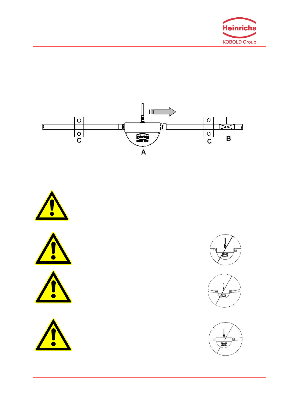
4.4.1 Installation
The sensor is to be protected, wherever possible, against valves, manifolds and similar fittings that
generate turbulence. The sensor is to be installed in accordance with the following instructions.
Diagram showing flow meter installation
Flow meter installation: A = sensor, B = valve, C = pipe clamps and supports
Warnings:
Page 18
Page 18 of 105
OPERATING MANUAL HPC & UMC4
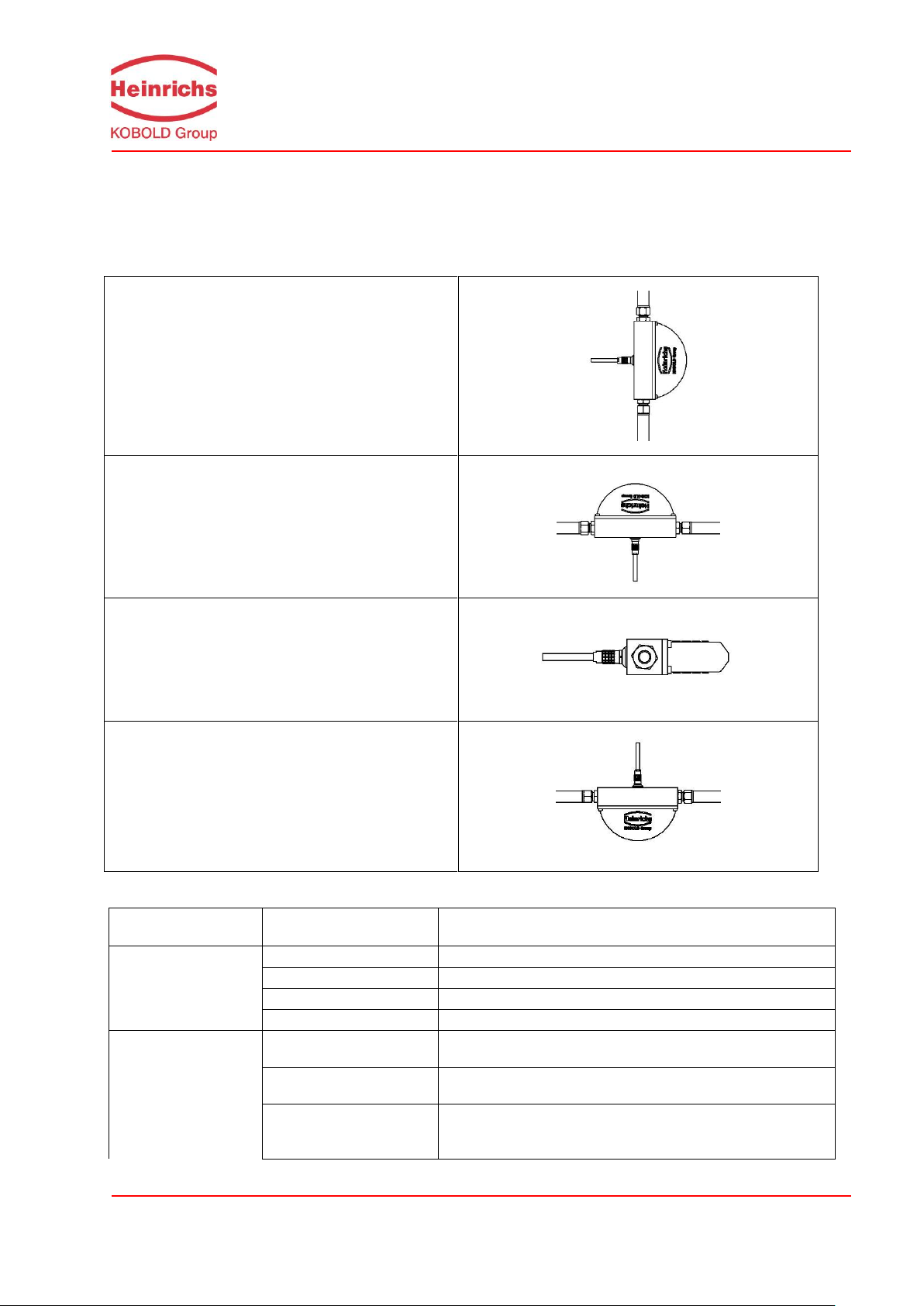
Standard Installation position A
Installation position B
Installation position C
Installation position D
Type of fluid
Position
Assessment
Pure liquids
Standard Position A
Self-draining flow tubes, recommended position
Position B
OK Position C
OK
Position D
Liquid residue remains in pipe
Liquids with gas bubbles
Standard Position A
Self-draining flow tubes, gas bubbles will not accumulate
in the tubes
Position B
Not recommended owing to gas bubble accumulation in
the tubes
Position C
Gas bubbles may accumulate in the presence of low flow
velocities
4.4.2 Installation positions
The HPC may be installed and will be fully functional in any number of positions. The following images
demonstrate the most common means of pipe installation as well as delivering tips for preventing the
orientation of the mounted device from influencing the measurement.
4.4.2.1 Assessment of the installation position
Page 19

OPERATING MANUAL HPC & UMC4
Page 19 of 105
Type of fluid
Position
Assessment
Position D
No gas bubble accumulation in the tubes, liquid residues
may however remain in the sensor after discharge
Liquids containing
substances that could
form deposits
Standard Position A
Self-draining flow tubes, no deposit formation
Position B
OK
Position C
Substances in the liquid could form deposits at low flow
velocities
Position D
Not recommended owing to the presence of substances
that could form deposits in the tubes
Liquids containing
gas bubbles, as well
as substances that
could form deposits
Standard Position A
Self-draining flow tubes, no accumulation of gases or
forming of substance deposits in the tubes
Position B
Not recommended owing to gas bubble accumulation in
the tubes
Position C
Gas bubbles or substances could form deposits at low
flow velocities
Position D
Not recommended, substances could form deposits in
the tubes
Gases that do not
form a condensate
Position A, B, C or D
Any of the installation positions may be used
Gas, condensateforming gas/liquid,
moisture
Standard Position A
Flow direction should be from top to bottom to ensure
forming condensate can flow out efficiently
Position B
OK
Position C
Condensate might form in the tubes
Position D
Not recommended owing to condensate accumulation in
the tubes
Slurries
Standard Position A
Optimal installation position
Position B
High density substances could accumulate in the tubes
Position C
Gas bubbles could accumulate
Position D
Gas bubbles or high density substances could accumulate in the tubes
4.4.3 Pressure surges
Pressure surges in a pipe could be provoked by a sudden decrease in flow caused by rapid closing of
a valve or similar factors. This change in pressure can lead to negative pressure downstream from a
valve that has been closed rapidly, and to outgassing. If the valve is mounted directly on the inlet section of the flow meter, a gas bubble can form in the flow tube that can cause a measuring signal disturbance which would shift the zero point of the output signal. In extreme cases, a pressure surge
could cause mechanical damage to the sensors and/or flow tubes.
Whenever possible, quick-closing valves should be mounted downstream from the sensor. If this is not
feasible, such valves are to be mounted a minimum of 10 x DIA (Φ) from the nearest sensor. Alternatively, valve closing speed can be reduced.
Page 20
Page 20 of 105
OPERATING MANUAL HPC & UMC4
4.4.4 Using the device with hazardous fluids
The sealing technology used in the standard HPC mass flow meter renders the device unsuitable for
use with hazardous fluids. Only sensors that meet the standards for safety instruments are suitable for
use with hazardous fluids.
The pathway between the sensor and transmitter must be pressure-tight so as to prevent fluid from
leaking out of a sensor in the event a sensor develops a defect.
In the case of welded components, a colored liquid penetration test may be performed on the welds, or
one joint (only the foremost seam) may be x-rayed. Alternatively, an internal pressure monitoring device can be used to detect any defect.
4.4.5 Vibration stability
The sensors are insensitive to vibration; vibration stability has been validated in accordance with
DIN IEC 68-2-6, for up to 1 g at 10 to 150 Hz.
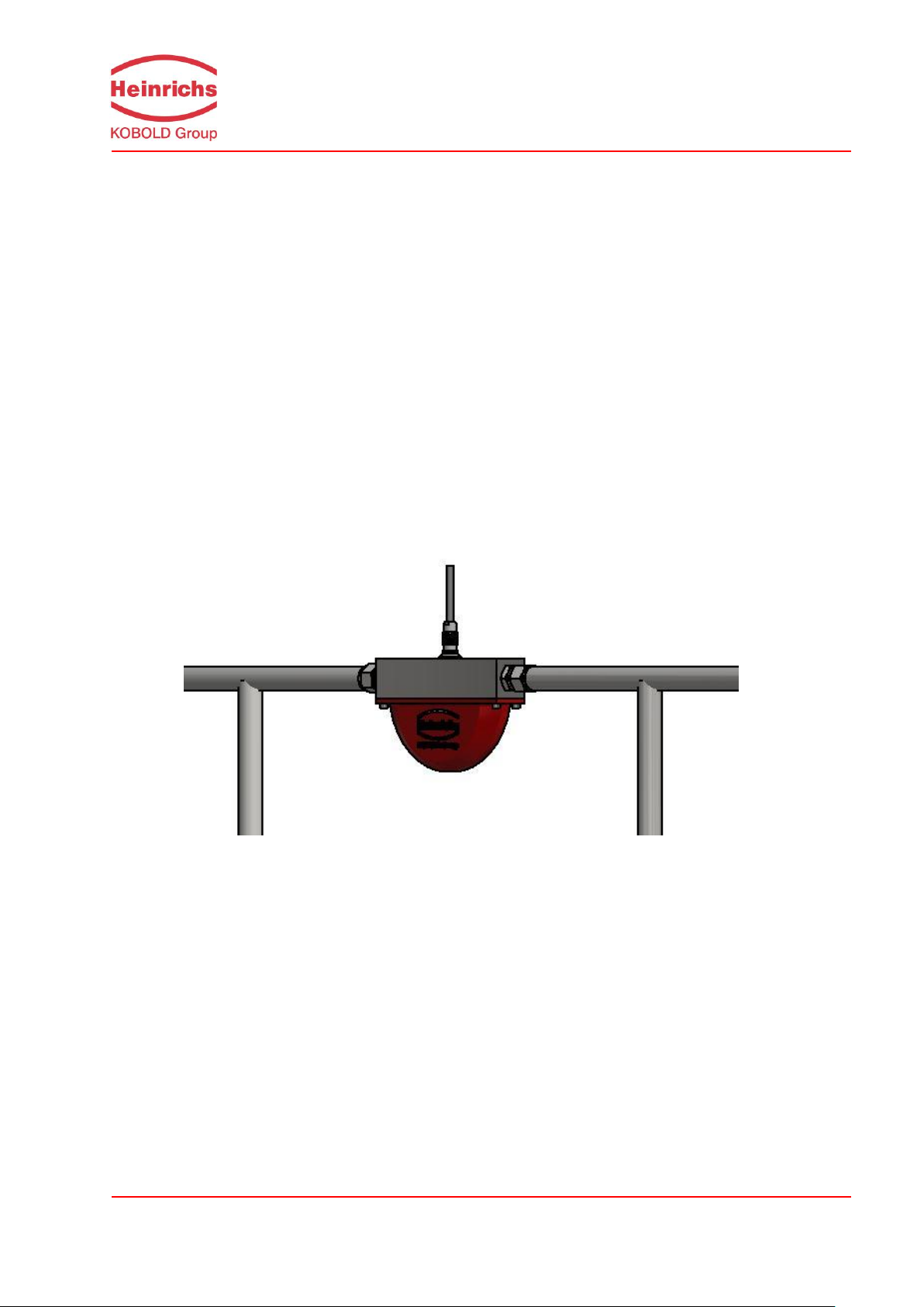
If pipe vibration is greater than 1 g in the 5-2000 Hz range, additional mounting supports are to be
installed as shown in the following drawing. These supports will prevent vibration from affecting the
device’s mechanical configuration and/or measurement readings.
Installation example
The above example represents a pipeline installation. The table and wall variant, with their accessories, are not affected by the representation.
Page 21

OPERATING MANUAL HPC & UMC4
Page 21 of 105
4.5 Process conditions
4.5.1 Process temperature
− 40 °C to 180 °C (-40 °F to 356 °F); rating plate specifications are to be observed
4.5.2 Physical state
Liquid product (maximum density 2 kg/l)
Gaseous product (minimum density 0.002 kg/l in operating state)
4.5.3 Viscosity
0.3 to 2,000 mPas (0.3 to 2,000 cP)
4.5.4 Gas content
The use of products containing gas will increase the measurement error. To have any chance of
achieving an acceptable measurement of a gaseous liquid, it is essential that the gas bubbles are as
small as possible and that they are homogeneously distributed in the fluid. Large gas bubbles will provoke grave measurement errors, and may also shift the zero point. Thus, the process conditions
gravely influence the measurement accuracy of the meter. With this in mind, a rule of thumb is: 1 %
gas component will increase false readings by 1 %. The gas component to exceed 5 %.
4.5.5 Process temperature range
+ 180 °C (356 °F)
4.5.6 Process pressure range
According to PN100 pressure rating = 100 bar / PN 320 320bar / PN400 = 400 bar
4.5.7 Outlet pressure
Outlet pressure must be greater than the vapor pressure ps of the measured product.
4.6 Connection to the transmitter
In consideration of its small dimensions, the transmitter cannot be mounted directly onto the
HPC sensor.
The connection to the sensor is achieved by means of a detachable cable connector.
During installation, regulations and applicable legal standards are to be adhered to.
The maximum cable length is 300 m (1000ft). See Section 12.5.1.2 “Connection of the sensor” on
page 37 for information regarding the connection and cable specifications.
Page 22

Page 22 of 105
OPERATING MANUAL HPC & UMC4
A
Model
Process connection
Sensor length (without connector)
mm [inch]
HPC-S01
G1/2 AG,
½ NPT(F),
Gyrolok 6/8/10 mm,
Swagelok 6/10/12 mm
150
[5,9]
HPC-S02
G1/2 AG,
½ NPT(F),
Gyrolok 6/8/10 mm,
Swagelok 6/10/12 mm
150
[5,9]
HPC-S03
G1/2 AG,
½ NPT(F),
Gyrolok 6/8/10 mm,
Swagelok 6/10/12 mm
150
[5,9]
Weight
Sensor
Transmitter
Model
DN
kg
[lbs]
kg
[lbs]
HPC-S01
G 1/2
1,8
[4,0]
HPC-S02
G 1/2
1,8
[4,0]
4,5
[9,9]
HPC-S03
G 1/2
1,8
[4,0]
4.7 Construction details
4.7.1 Dimensions and weight
Dimensions:
Weight:
Page 23
OPERATING MANUAL HPC & UMC4
Page 23 of 105
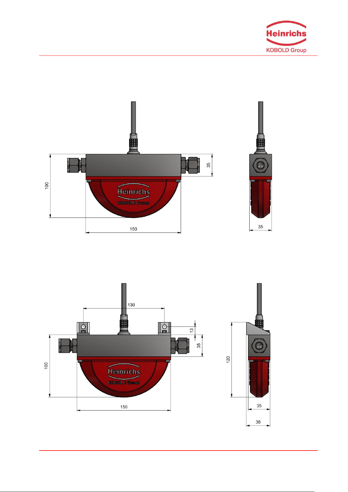
4.7.2 Dimension drawings for the types HPC-S01 to HPC-S03
4.7.2.1 Dimensional drawing of the pipe mounted version
For all dimensions and weight, see Section 4.7.1 Dimensions and weight on page 22.
4.7.2.2 Dimensional drawing of the wall mounted version
For all dimensions and weights, see Section 4.7.1 Dimensions and weight on page 22.
Page 24
Page 24 of 105
OPERATING MANUAL HPC & UMC4
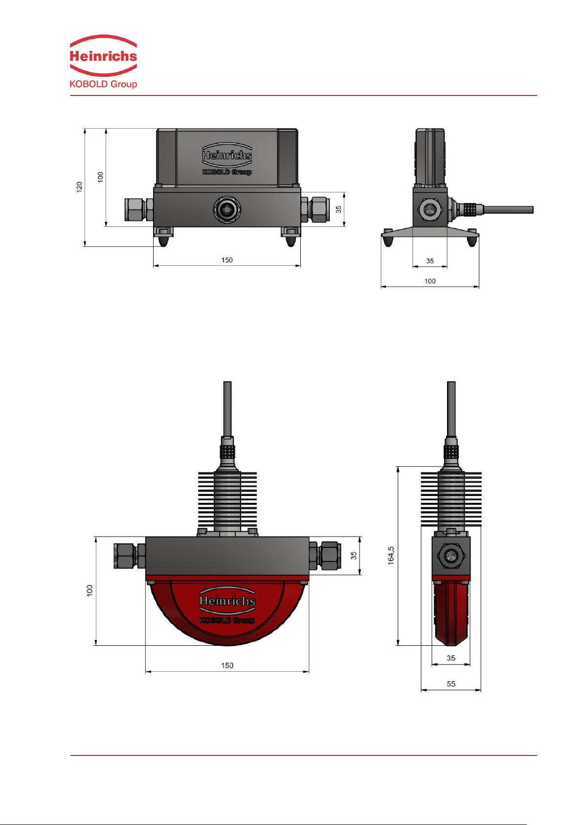
4.7.2.3 Dimensional drawing of the Table top version
For all dimensions and weights, see Section 4.7.1 Dimensions and weight on page 22.
4.7.2.4 Dimensional drawing of the 180°C high temperature version
For all dimensions and weights, see Section 4.7.1 Dimensions and weight on page 22.
Page 25

OPERATING MANUAL HPC & UMC4
Page 25 of 105
4.7.3 Material
Sensor Containment:
HPC-S01 to HPC-S03: Stainless steel 1.4571 (316Ti)
Stainless steel 1.4404 (316L)
Sensor lid:
HPC-S01 bis HPC-S03: Aluminum, Eloxated aluminium, Stainless Steel
Flow tubes: 1.4571 (316Ti),
Flow distribution block: 1.4404 (316L)
or Hastelloy, Tantalum, or other materials on
request
4.8 Sensor HPC approvals
4.8.1 CE marking
See also section 18 “Declaration of Conformity” on page 102
Pressure Equipment Directive 2014/68/EU
EMC Directive 2014/30/EU
EN 61000-6-3:2011 Störaussendung
EN 61000-6-2:2011 Störfestigkeit
Page 26

Page 26 of 105
OPERATING MANUAL HPC & UMC4
5. Commissioning
5.1 Zero point calibration
In order to ensure that precise measurements are obtained, zero point calibration is to be Performed the
first time the device is put into operation and before any regular operations are carried out. Zero point
calibration is to be performed using a fluid.
The zero calibration procedure is as follows:
Install the sensor as described in the manufacturer’s instructions.
Check to ensure that the sensor is completely filled with fluid and that there are no gas bub-
bles in the flow tubes.
Define the process conditions such as pressure, temperature and density.
Close a potential shut-off device behind the sensor.
Operate the transmitter in accordance with the instructions in Section 14.4.4 Zero point cal-
ibration on page 57.
Make sure that sufficient time is allowed for the electronics to warm up.
Allowing fluid to flow through the sensor during the zero calibration procedure will skew the
zero point and result in false readings, especially during low flow conditions.
5.2 Startup conditions
The device is not subject to specific startup conditions. However, pressure surges should be avoided.
Page 27

OPERATING MANUAL HPC & UMC4
Page 27 of 105
Warning
Only sensors and transmitters marked as Ex-proofed on their rating plates may be
used in Ex hazardous areas!
Standard equipment is prohibited for use in Ex hazardous areas.
6. Application domain of the UMC4 transmitter
The microprocessor controlled UMC4 transmitter (hereinafter referred to as UMC4) for use with TM, TME
TMR, TMU and HPC sensors is a programmable transmitter which processes measurement data and
displays and transmits various types of measurement results.
The UMC4 is capable of communication and supports the HART® protocol. The device can be customized using the standard installed control unit BE4. Although basic configuration settings such as transmitter calibration are carried out at the factory, other settings such as those for measurement data processing, analysis, display and output are user definable.
User settings are protected by a user definable password. The user password can be changed by the
customer.
Settings that are essential for proper operation of the transmitter in conjunction with the sensor (e.g. calibration and initialization values) are accessible only to service technicians via a password that is not provided to customers.
7. UMC4 transmitter: mode of operation and configuration
7.1 Measuring principle
The Coriolis mass flow meter is based on the principle that in a rotating system a force (known as Coriolis
force) is exerted on a mass at a rotation point that is moving towards or away from this point. By configuring the sensor in a specific fashion, this force can be used to measure mass flow directly. The UMC4
transmitter evaluates the sensor signal (see Section 4.2.1 Measuring principle on page 14).
7.2 System configuration
Transmitter:
The UMC4 transmitter regulates the excitation of the sensor vibration system and processes the sensor
signals. The standard model is equipped with two analog, passive 4 to 20 mA outputs, an impulse or frequency output and a status output, and is enabled for digital data transfer via the HART® protocol.
Sensor:
The sensors measure mass-flow, density and temperature of fluids or gases. The device can be used to
perform measurements with any liquid or gaseous product providing that the sensor material is suitable
for the product being used.
Page 28
Page 28 of 105
OPERATING MANUAL HPC & UMC4
Warning
Make sure that you abide by the applicable standards and regulations pertaining to electrical devices, device installation and process technology when replacing the transmitter electronics. The highly integrated electronic components
in the device carry the risk of ESD hazards and are only protected when installed in the device pursuant to EMC standards.
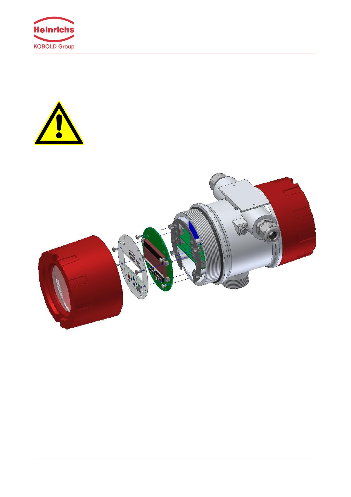
7.2.1 DSB data memory module
The replaceable plug and play memory device is integrated on the PCB of the control unit where all sensor data such as sensor constants, model numbers, serial numbers, and so on are stored. Consequently,
the memory module is linked to the sensor. If the transmitter’s electronics are exchanged for any reason,
the control unit BE4 must be removed from the old and placed onto the new electronic stack.
The removal and insertion of the control unit is performed as can be seen in the following sketch.
After removing 4 screws, the control unit with the display can be detached.
If the transmitter is replaced, the control unit should be transferred to the new transmitters electronic
stack. When the flow meter is powered up, the device continues using the values stored in the memory
device. Thus, the DSB memory device provides maximum safety and comfort when device components
are replaced.
The control units are not interchangeable arbitrarily between identically constructed transmitters
due to the memory device. Replaceable circuit boards must be ordered from Heinrichs using the trans-
mitter’s serial number specification. The calibration data of the sensor are programmed into the delivered
BE4 control panel directly by the manufacturer.
Page 29

OPERATING MANUAL HPC & UMC4
Page 29 of 105
8. Input
8.1 Measured variable
Mass flow rate, temperature, density and volume flow (calculated from the preceding measured variables).
8.2 Measuring range
The measuring range, which varies according to the used sensor, can be found on the relevant data
sheet or rating plate (see Section 4.3.2 HPC flow ranges on page 15).
9. Output
9.1 Output signal
All signal outputs Electrically isolated from each other and to ground
Analog outputs 2 x 4 to 20 mA passive
Current output 1:
Mass flow, volume flow, density, temperature
(when using the HART® protocol, output 1 is assigned to mass
flow)
Current output 2:
Mass flow, volume flow, density, temperature
Pulse output Pulse duration: default value 50 ms
(Binary output 1) Pulse duration: adjustable range is 0.1 to 2000 ms
Mark-to-space ratio is 1:1 if the set pulse duration is not reached.
As a frequency output 1 kHz
passive via optocoupler
U
= 24 V
nom
U
= 30 V
max
I
= 60 mA
max
P
= 1,8 W
max
Pulse value settable in decade increments of selected pulse unit,
e.g. kg or m³.
Status output For: forward and reverse flow, MIN flow rate, MAX flow rate, MIN
density, MAX density, MIN temperature, MAX temperature, alarm
Second pulse output (out of phase by 90°)
Passive via optocoupler
U
= 24 V
nom
U
= 30 V
max
I
= 60 mA
max
P
= 1,8 W
max
Page 30

Page 30 of 105
OPERATING MANUAL HPC & UMC4
500
23
110
max
mA
VU
R
0 Ohm
100 Ohm
200 Ohm
300 Ohm
400 Ohm
500 Ohm
600 Ohm
0 V 5 V 10 V 15 V 20 V 25 V 30 V
load
external power supply voltage
maximum load
Rmax
9.2 Failure signal
A failure in the meter can be indicated via the current outputs or the status output. The current outputs
can be set to a failure signal (alarm) of I < 3.8 mA or I > 22 mA. The status output can be configured as
make or break contact.
9.3 Load
Standard version: 500 ohms
Explosion-proof version: 500 ohms
HART minimum load: > 250 ohms
10 V is the minimal needed voltage at passive current output terminals. The maximum voltage of 30 V
must never be exceeded. The maximum load is calculated according to the equation:
9.4 Damping
Programmable from 1 to 60 seconds
9.5 Low flow cutoff
The low flow cutoff can be set to values between 0 and 20% using the software. The set value refers to
the upper-range value. If the measured value is lower than the set volume, the flow rate will set to 0.0
(kg/h). This results in the analog output being set to 0/4 mA, and the pulse output will stop generating
pulses.
Page 31

OPERATING MANUAL HPC & UMC4
Page 31 of 105
10. UMC4 performance characteristics
10.1 Reference conditions
In conformity with IEC 770
Temperature: 20 °C (68 °F), relative humidity: 65 %, air pressure: 101.3 kPa (14.7 psi)
10.2 Measured error
Measured error and zero point stability see sensor data sheet or Section 4.3.2 HPC flow ranges on
page 15.
10.3 Repeatability error
0.05 % of actual value (sensor with transmitter). See section 4.3.2 HPC flow ranges on page 15.
10.4 Influence of ambient temperature
0.05 % per 10 K
Page 32

Page 32 of 105
OPERATING MANUAL HPC & UMC4
Warning:
Additional cable glands:
They are not contained in the scope of supply. The operator is responsible
for guaranteeing that cable glands or screws according to the enclosures
certification are used. The type of thread present is stated on the rating
plate.
For the connection between sensor and transmitter a metalized cable gland
must be used for the screen.
(See 12.5.1.2 “Connection of the sensor” page 37)
Danger:
It is the customer’s responsibility to ensure the NPT adapters are mounted
securely! Only correctly tightened adapters will guarantee the Ex-d protection
class of the enclosure!
Warning:
Ingress protection IP 68 can only be achieved if suitable and sufficiently tightened cable glands or conduits are used. If the cable glands are only tightened
sufficiently, water may leak into the terminal compartment of the enclosure.
Danger:
Particular care must be taken if the enclosure’s window becomes fogged or
discolored. This could mean that moisture, water or product is seeping through
the wire sheath into the transmitter’s housing.
11. UMC4 operating conditions
11.1 Installation conditions and cable glands
When mounting the UMC4 transmitter, a vibration-free installation site must be guaranteed.
11.2 NPT cable glands
The transmitter housing SG4 is designed with M20x1.5 threads for cable glands. For cable glands with
NPT thread, a certified matching NPT adapter may be ordered directly from the manufacturer. These
NPT adapters are to be directly mounted onto the UMC4’s transmitter housing.
11.3 Environmental conditions
11.3.1 Ambient temperature
− 20 °C to + 60 °C (-4 °F to 140 °F), below 0 °C (32 °F) the readability of the LC display will be limited
11.3.2 Ambient temperature range
− 20 °C to + 60 °C (-4 °F to 140 °F)
11.3.3 Storage temperature
−25 °C to + 60 °C (-13 °F to 140 °F)
11.3.4 Ingress protection
Standard enclosure SG4, IP 68 (NEMA 6P)
Explosion-proof Ex d electronics enclosure
Terminal compartment: with terminals and Ex e “Increased safety” type of protection, or alternatively
Ex d
Page 33

OPERATING MANUAL HPC & UMC4
Page 33 of 105
Warning
Electromagnetic compatibility is only achieved if the electronics enclosure is
closed. Leaving the enclosure open can lead to electromagnetic disturbances.
Warning
In Ex hazardous areas, only sensors and transmitters with approvals marked
on the rating plates may be used!
11.4 Process conditions
11.4.1 Integrally Mounted transmitter
In combination with the HPC sensors, the UMC4 transmitter is always mounted separately (remote)
from the sensor. For the TM* series of sensors, the following parameters are valid
11.4.1.1 Process fluid temperature
− 40 °C to + 180 °C (-40 °F to 356 °F)
The data sheet/rating plate of the connected transmitter must be observed.
11.4.1.2 Fluid temperature limit
180 °C (356 °F)
The data sheet of the connected transmitter must be observed.
11.4.1.3 Vibrations
In accordance with DIN IEC 68-2-6, for up to 1 g at 10 to 150 Hz.
11.4.2 Remote mounted transmitter
In the remote mounted configuration, the process conditions of the sensor have no influence on the
transmitter
Page 34

Page 34 of 105
OPERATING MANUAL HPC & UMC4
12. Construction details
12.1 Type of construction/dimensions
Horizontal pipe mounting – SG4
Vertical pipe mounting – SG4
Page 35

OPERATING MANUAL HPC & UMC4
Page 35 of 105
Wall mounting
Pipe mounting with a junction box
Page 36

Page 36 of 105
OPERATING MANUAL HPC & UMC4
Main voltage rated Current rated voltage breaking capacity
90V ... 265V AC 250mAT 250V AC 1500A / 250V AC
24V AV 250mAT 250V AC 1500A / 250V AC
19V ... 36V DC 250mAT 250V AC 1500A / 250V AC
Designation
Terminal / Pin designation
Type of protection
Standard
Ex ia
(Non Ex)
Power supply
L or “+”
L
x
N or “-“
N
x
PE
PE
x
12.2 Weight
Approx. 2.4 kg (5.5 lbs) (separate UMC4 transmitter without mounting system)
12.3 Material
Enclosure: Painted aluminum pressure die–casting, max.0.5% Mg; yellow chromating.
12.4 End connection
To connect the remote sensor to the transmitter, a special connection cable must be used.
For further details see Sections 4.6 “Connection to the transmitter” on page 21, and 12.5.1.2 Connection of the sensor on page 37.
12.5 Electrical connections and their protection classes
Auxiliary power 90 V - 265 V AC 50/60 Hz
24 V AC + 5 %, − 20 % 50/60 Hz
19 V to 36 V DC
Power input 4.5 VA
Main fuse: 5x20 mm IEC 60127-2
Supplier: Little Fuse Series 0215.250 HXP
12.5.1 Wiring diagrams
12.5.1.1 Power connections
Power connection terminals
Page 37

OPERATING MANUAL HPC & UMC4
Page 37 of 105
Designation
Terminal / Pin designation
Type of protection
Standard
Ex ia
(Non-Ex)
Sensor lines
SENSOR1 +
1
x x
SENSOR1 -
2
x x
SENSOR2 +
3
x x
SENSOR2 -
4
x x
TIk- 5 x x
Temperature sensor -
6
x x
Temperature sensor +
7
x x
TIk+ 8 x x
EXCITER1
9
x x
EXCITER2
10
x x
Shield
Shield
x x
Warning:
The colors of the sensor’s wires may differ to the colors of the connection
cable’s wires between terminal box and transmitter! The colors shown in the
drawing above only refers to the numbers of the terminal in the terminal box
and transmitter.
12.5.1.2 Connection of the sensor
Sensor and transmitter are always mounted separately. For the connection between the sensor and
transmitter one of the following cables is to be used:
Non-explosion proof applications SLI2Y(ST)CY 5 x 2 x 0.5 mm² grey (max. 300 m)
Explosion-proof applications SLI2Y(ST)CY 5 x 2 x 0.5 mm² blue (max. 300 m)
(blue for explosion-proof applications, grey for non-explosion proof applications).
Attention: Cables not certified by the manufacturer may impair the accuracy of the measurement as
well as EMC compliance.
The outer shield is connected to the junction box cable gland at one end, and the connectors outercase at the other end. The inner shields of the wire-pairs are connected to each other (drilled together)
and connected to the “Schirm / shield” terminal in the junction box.
Alternative cables:
SLI2Y (ST) C11YÖ 5 x 2 x 0.5 mm or
SG [5(2 LiY 0.50)St]FStC11Y
Page 38

Page 38 of 105
OPERATING MANUAL HPC & UMC4
UMC4 with pig-tail connection cable
For connector pin assignment, see the table on page 37
Advices for cable glands: See also 11.1 “Installation conditions and cable glands” on page 32.
UMC4 junction box and WAGO terminals
For terminal assignment, see the table on page 37
Advices for cable glands: See also 11.1 “Installation conditions and cable glands” on page 32.
Page 39

OPERATING MANUAL HPC & UMC4
Page 39 of 105
Designation
Terminal designation
Type of protection
Standard
Signal outputs
Ex ia
(Ex d)
non-Ex ia
(Non-Ex)
Current 1, 4 to 20mA with
HART®
11 and 12
x x
41 and 42
x
Current 2, 4 to 20mA
13 and 14
x x
43 and 44
x
Binary output 1
(passive pulse)
16 and 17
x x
46 and 47
x
Binary output 2 (status or 2nd
passive pulse output)
19 and 20
x x
49 and 50
x
Option
Binary output 3
33 and 34
x x
53 and 54
x
12.5.2 The output signals
The output signals of the UMC4 are available in various Ex protection classes. The terminal designations vary depending on the protection class ordered.
The terminal designation and their protection class can be taken from the following table:
12.5.3 HART®
A number of options are available for HART® communication. However, for all these options loop resistance must be less than the maximum load specified in Section 9.3 Load (on page 30). The HART®
interface is connected via terminal 11 and 12 or 41 and 42 with a minimum load impedance of 250 Ω.
For information regarding operation of the transmitter using the HART hand-held terminal, see “Operation of the UMC4 transmitter using the HART hand-held terminal.”
12.5.4 Communication via Siemens PDM®
PDM® is the configuration software of Siemens that is used to operate HART® or Profibus PA compatible devices.
To connect a desktop or laptop computer to the UMC4, a HART® interface is required in addition to
communication software such as PDM. The HART® interface, which has two connections, converts the
levels of the RS 232 interface or USB interface into an FSK signal (frequency-shift keying).
Output Signals in Ex-ia type of protection
Page 40

Page 40 of 105
OPERATING MANUAL HPC & UMC4
13. Control unit BE4
13.1 Introduction
The UMC4 transmitter can be operated using control unit BE4, a desktop or laptop computer in conjunction with PDM® software, or via HART® Communicator.
In the following, transmitter operation and parameterization are described using control unit BE4 integrated into the electronic compartment. To use the control unit the cover window glass must be removed.
In Ex hazardous area, all relevant safety regulations have to be observed before opening the
window glass.
Control unit BE 4
13.2 Display
Control unit BE4 in the UMC4 has an integrated alphanumeric display with two 16-character lines
(format 15 x 52 mm). To improve the readability of the display at low ambient brightness, it is equipped
with a backlight. Measurement data and settings can be read directly from this display.
The LCD display is designed for operation at temperatures ranging from − 20 °C to + 60 °C (-4° F to
140 °F) without incurring any damage. However, at freezing or near-freezing temperatures, the display
becomes slow and readability of the measured values is reduced. At temperatures below − 10 C°
(14 °F), only static values (parameter settings) can be displayed. At temperatures exceeding 60 C°
(140 °F), contrast decreases substantially. When submitted to higher temperatures for long periods of
time, the liquid crystals may dry out.
Page 41

OPERATING MANUAL HPC & UMC4
Page 41 of 105
Functional class
Functional class
Function with
numerical Input
Function with
numerical Input
Display
Display
Legend
Numerical Input
153.40
Function
value selected
from list
Function
value selected
from list
Selection
[no]
___________
no
yes
Parameter level
Headline
Main menu
Menu level subpoint
Functionial class
Functionial class
13.3 Operating modes
The UMC4 can be operated in the following modes:
1. Display mode: In display mode, measured values can be displayed in various
combinations and UMC4 settings can also be displayed. Parameter settings cannot be changed in this mode. Display mode is the
standard (default) operating mode when the device is switched on.
2. Programming mode: In programming mode, UMC4 parameters can be redefined. After
entering the correct password, changes that are permissible for the
customer (customer password) or all functions (service password
for technicians) can be realized.
13.4 Operation
13.4.1 Operator interface
Functional classes are displayed
as headings beneath which displays
and parameters are shown in logical
groups.
Beneath this is the menu level,
which lists all measured value displays or the headings for their underlying parameters (parameter
level).
All functional classes are interlinked
horizontally, while all sub-menus
that are assigned to a functional
class are displayed beneath the
relevant class.
Page 42

Page 42 of 105
OPERATING MANUAL HPC & UMC4
Important note
Do not press these keys with sharp or sharp-edged objects such as pencils or
screwdrivers.
Descriptor
Symbol
Cursor key, arrow to the right
Cursor key, arrow to the left
Cursor key, arrow to the top
Cursor key, arrow to the bottom
13.4.2 The keys and their functions
There are six keys to change the settings.
Cursor keys: Using the cursor keys, the operator can change numerical values, give YES/NO answers
Esc key: The “Esc” key allows you to cancel the current action. Pressing Esc moves you to
ENTER key: Pressing the „Enter“ key moves you from the menu level to the parameter level. You
and select parameters. Each key is assigned a symbol in the following table:
the next higher level where the operator can repeat the action. Pressing Esc twice moves
you directly to the MEASURED VALUES functional class.
confirm all entries with the „Enter“ key.
Page 43

OPERATING MANUAL HPC & UMC4
Page 43 of 105
Function name
[Selection]
Function name
-4,567 Unit
13.4.3 Functional classes, functions and parameters
Functional classes are written in all upper case letters (headings). The functions beneath each functional
class are written in upper and lower case.
The various functional classes and functions are describes in Section 14 “UMC4 transmitter functions”
starting on page 45.
The lower line contains the following elements:
- Informational texts
- YES/NO answers
- Alternative values
- Numerical values (with dimensions, if applicable)
- Error messages
If the user attempts to modify values for any of these parameters without entering the required password,
the message “Access denied” will be displayed (see also 13.3 Operating modes on page 41 and 13.4.3.3
Pas on page 44).
13.4.3.1 Selection window/make a selection
In the selection window, the first line of the LCD always contains the heading, while the second line displays the current setting. This setting is shown in square brackets if the system is in Programming mode.
In Programming mode (see 13.3 Operating modes on page 41), i.e. after a password has been entered
(see 13.4.3.3 Passwords on page 44), the operator can navigate to the desired setting by using the key
or the key and the operator can then confirm your selection by pressing the Enter key. To retain the
current setting, press Esc.
13.4.3.2 Input window/modify a value
In the input window, the first line of the LCD always shows the heading, while the second line shows the
current setting.
Example:
These modifications can only be made in Programming mode (refer to 13.3 Operating modes on page
41), which means that a correct password (see 13.4.3.3 Passwords on page 44) must be entered. To
move the cursor from one decimal place to the next, use theorkeys. To increase the value of the
decimal place just under the cursor by “1,” use thekey, and use key to lower the number by 1. To
change the minus and plus sign, place the cursor in front of the first digit. To confirm and apply the
change, press Enter . To retain the current value, press Esc.
Page 44

Page 44 of 105
OPERATING MANUAL HPC & UMC4
13.4.3.3 Passwords
Programming mode is password protected. The customer password allows all changes to be made that
are permissible for customers. This password can be changed when the device is first put into operation.
Should the password be changed, retain the new password in a safe place.
The UMC4 customer password in the device when delivered is 0002.
The service password allows for modification of all UMC4 functions. This password is not given to cus-
tomers.
For further information on customer passwords, see Section 14.2 PASSWORD functional class on page
51.
Page 45

OPERATING MANUAL HPC & UMC4
Page 45 of 105
Function Overview
(Main Menue UMC4)
MEASURED
VALUES
MEASURED
VALUES
PASSWORD
PASSWORD
COUNTER
COUNTER
MEASUREMENT
PROCESSING
MEASUREMENT
PROCESSING
FLOW
FLOW
DENSITY
DENSITY
TEMPERATURE
TEMPERATURE
PULSE OUTPUT
PULSE OUTPUT
CURRENT
OUTPUT
CURRENT
OUTPUT
STATUS
STATUS
SELF-TEST
SELF-TEST
SIMULATION
SIMULATION
TRANSMITTER
SETTINGS
UMC4
TRANSMITTER
SETTINGS
UMC4
SENSOR
SETTINGS
SENSOR
SETTINGS
14. UMC4 transmitter functions
The software functions of the UMC4 transmitter are divided into functional classes, are arrayed in a circle
and can be navigated by using the orcursor keys. To go back to your starting point (the MEASURED
VALUES functional class) press Esc.
In the following, all software functions that can be accessed using the customer password are described.
Functions that are only accessible to the vendor (service functions) are not described in the present document.
Page 46

Page 46 of 105
OPERATING MANUAL HPC & UMC4
MEASURED VALUES
MEASURED VALUES
Mass flow
(QM)
Mass flow
(QM)
Volume flow
(QV)
Volume flow
(QV)
Counter forward
(F)
Counter forward
(F)
Counter reverse
(R)
Counter reverse
(R)
Density
Density
Temperature
Temperature
Mass flow
Counter (F)
Mass flow
Counter (F)
Raw values
Raw values
Mass flow
Temperature
Mass flow
Temperature
Display mode
start -up
Display mode
start -up
Mass flow
Density
Mass flow
Density
MEASURED VALUES
functional class
Display mode
[QM]
_______________
QM
QV
Counter F
Counter R
Density
Temperature
QM + Counter F
QM + Density
QM + temperature
QV + Counter F
QV + Density
Raw values
QV
Counter (F)
QV
Counter (F)
QV
Density
QV
Density
Elapsed time
d h min
Elapsed time
d h min
14.1 MEASURED VALUES functional class
The MEASURED VALUES functional class contains all functions for displaying the measured values.
Page 47

OPERATING MANUAL HPC & UMC4
Page 47 of 105
Mass flow
XXX.X kg/h
Volume flow
XXX.X m³/h
Counter forward
XXXXXXXX.XX kg
Counter reverse
XXXXXXXX.XX kg
14.1.1 Mass flow
After selecting the Mass flow function, the following will be displayed:
The LCD shows the current mass flow. The operator can define the display unit in the FLOW functional
class using the Mass flow QM unit function.
14.1.2 Volume flow
After selecting the Volume flow function, the following will be displayed:
Volume flow can only be displayed if density measurement has been calibrated and activated. Otherwise,
an error message is displayed. The operator can define the display unit in the FLOW functional class
using the Volume flow QV unit function.
14.1.3 Counter forward
After selecting the Counter forward function, the current reading of the forward flow counter will be displayed.
The operator can define the display unit in the COUNTERS functional class using the Unit of counters
function.
14.1.4 Counter reverse
After selecting the Counter reverse function, the current reading of the reverse flow counter will be displayed.
The operator can define the display unit in the COUNTERS functional class using the Unit of counters
function.
Page 48

Page 48 of 105
OPERATING MANUAL HPC & UMC4
Density
XXX.X g/l
Temperature
XXX,XX °C
Elapsed time
256 d 18 h 06 min
XXX.X kg/h
XXXXXXXX.XX kg
14.1.5 Density
Depending on the settings in the DENSITY functional class, the process or reference density will be displayed. Density can only be displayed if the sensor is suitable for density measurement and has been
calibrated accordingly.
The operator can define the display unit in the DENSITY functional class using the Density unit function.
14.1.6 Temperature
After selecting the Temperature function, the following will be displayed:
The LCD shows the current temperature of the measured fluid in degrees Celsius, Fahrenheit or Kelvin.
14.1.7 Elapsed time
The LCD shows the operating time that has elapsed in d(ays), h(ours) and min(utes) since the system
was initialized and commissioned by the vendor:
14.1.8 Mass flow + Counter forward
After selecting the Mass flow + Counter forward function, the current mass flow will be displayed in the
first line of the LCD:
The second line shows the value of the counter forward. The operator can define the display unit in the
FLOW functional class using the Mass flow QM unit function and the counter unit using the Unit of coun-
ters function in the COUNTERS functional class.
Page 49

OPERATING MANUAL HPC & UMC4
Page 49 of 105
XXX.X kg/h
XXX.X g/cm³
XXX.X kg/h
XXX °C
XXX.X m³/h
XXXXXXXX.XX m³
XXX.X m³/h
XXX.X g/cm³
14.1.9 Mass flow + Density
After selecting the Mass flow + Density function, the following will be displayed:
The first line of the LCD shows the current mass flow and the second the density of the measured fluid.
You define the display unit in the FLOW functional class using the Mass flow QM unit function and the
density unit using the Density unit function in the DENSITY functional class.
14.1.10 Mass flow + Temperature
After selecting the Mass flow + Temperature function, the following will be displayed:
The first line of the LCD shows the current mass flow and the second line the temperature of the measured fluid. You define the display unit in the FLOW functional class using the Mass flow QM unit function.
14.1.11 Volume flow + Counter forward
After selecting the Volume flow + Counter forward function, the current mass flow will be displayed in the
first line of the LCD:
The second line shows the value of the counter forward. The operator can define the display unit in the
FLOW functional class using the Volume flow QV unit function and the counter unit using the Unit of
counters function in the COUNTERS functional class.
14.1.12 Volume flow + Density
After selecting the Volume flow + Density function, the following will be displayed:
The first line of the LCD shows the current volume flow and the second line the density of the measured
fluid. The operator can define the display unit in the FLOW functional class using the Volume flow QM
unit function and the unit for density measurement in the DENSITY functional class using the Density unit
function.
Page 50

Page 50 of 105
OPERATING MANUAL HPC & UMC4
Display mode
[QM]
xxx.xxx ttt.tttt
fff.ffff eee.aaa
14.1.13 Display mode during startup
By choosing the Display mode during startup function the operator can define the default display. After
the operator switched the device on and did not touch any keys for a longer period of time, the defined
default display will be shown:
According to the description in Section 13.4.3.1 Selection window/make a selection, one of the following
default displays can be selected.
QM (Mass flow)
QV (Volume flow)
Counter f(orward)
Counter r(everse)
Density
Temperature
QM + Counter f
QM + Density
QM + Temperature
QV + Counter f
QV + Density
and Raw values
14.1.14 Raw values
The “Raw values display” supports fault diagnosis and trouble shooting. Please inform our service department about the clear text error messages and the contents of this “Raw values display.”
The displayed values have the following meaning:
xxx.xxx: Measure for the phase displacement between the sensor signals.
ttt.ttt: Indicates the measured sensor temperature.
fff.ffff: Indicates the current oscillation frequency of the system.
eee.aaa: Indicates the value of the excitation current (eee) and the sensor voltage (aaa).
Page 51

OPERATING MANUAL HPC & UMC4
Page 51 of 105
PASSWORD
PASSWORD
Customer
password
Customer
password
Change customer
password
Change customer
password
Service
password
Service
password
PASSWORD
functional class
Password ?
0000
Enter New password
0000
Password ?
0000
Password?
0000
Password
valid
Password
invalid
14.2 PASSWORD functional class
The PASSWORD functional class is comprised of the functions for entering and changing the customer
password and entering the service password. To cancel the current action, press Esc.
14.2.1 Customer password
After selecting the Customer password function and pressing „Enter“, the following will be displayed:
According to the description in Section 13.4.3.2 Input window/modify a value, the password can be
changed.
If the entered password is correct, the following message will be displayed:
If the entered password is not correct, the following message will be displayed:
The customer password in the device when delivered is 0002.
Page 52

Page 52 of 105
OPERATING MANUAL HPC & UMC4
Enter New password
0000
A valid customer password allows all software parameter changes to be made that are permissible for
customers. After the operator switched the device off or did not touch any keys for about 15 minutes, the
authorization to change settings related to password entry will automatically be canceled. If the operator
does not enter a valid password, all settings can be displayed but not changed. Parameter changes via
HART or Profibus PA may be carried out any time without entering password.
14.2.2 Change customer password
After entering a valid customer password, you may change the existing password and enter a new one.
After selecting the Change customer password function and pressing „Enter“, the following will be displayed.
According to the description in Section 13.4.3.2 Input window/modify a value the current value can be
changed.
Press „Enter“ to confirm and save the new password. Make sure that you entered the desired
password. A copy of the password should be kept in a safe place. Reactivation of a transmitter at the
vendor’s site due to a lost password is not part of our warranty.
14.2.3 Service password
You do not need the service password for setting the functions necessary for operation.
The service password is reserved for service technicians and not provided to customers. Correct settings
are essential for proper operation of the device (e.g. parameterization and calibration values).
Page 53

OPERATING MANUAL HPC & UMC4
Page 53 of 105
COUNTERS
COUNTERS
Unit of
counters
Unit of
counters
Reset
counters
Reset
counters
COUNTERS
functional class
Accumulation of:
[kg]
_________________
g
kg
t
m³
cm³
l
USG
UKG
USB
lbs
shton
lton
ft³
acft
oz
floz
xxQM
xxQV
Reset counters ?
[no]
________________
no
yes
14.3 COUNTER functional class
The COUNTERS functional class is comprised of the following functions:
To change the current settings, enter the customer password. Otherwise, the settings can only be displayed but not changed. To cancel the current action, press Esc.
Page 54

Page 54 of 105
OPERATING MANUAL HPC & UMC4
Accumulation of:
[kg]
Reset counters
[no]
14.3.1 Unit of counters
After choosing the Unit of counters function and pressing „Enter“, the current forward and reverse counter
unit will be displayed:
According to the description in Section 13.4.3.1 Selection window/make a selection, one of the following
units can be selected.
Mass units: g, kg and t as well as lbs, shton, lton and oz or
Volume units: m³, cm³ and l as well as USG, UKG, USB, ft³, acf and floz
Programmable mass unit: xxQM,
Programmable volume unit: xxQV.
When the unit is changed, the counters will be reset to 0.00 automatically.
The volume unit only makes sense if the sensor has been calibrated for density measurement. Press
„Enter“ to confirm and save the selection. Forward and reverse counters will now show the selected unit.
The valence of the programmable units are defined by the settings of the flow units described in sections
14.5.2 “Factor mass flow QM programmable unit” on page 59 and 14.5.8 “Factor volume flow QV programmable unit” on page 62.
14.3.1 Reset counters
To reset the totalizing counters, you definitely need to toggle to [yes]. Forward and reverse counters will
be reset at the same time (0.00).
According to the description in section 13.4.3.1 Selection window/make a selection, one of the indicated
units can be selected. By pressing Esc or toggling to [no] the operator can cancel the current action without changing the counter readings.
Page 55

OPERATING MANUAL HPC & UMC4
Page 55 of 105
Filter
Filter
MEASUREMENT
PROCESSING
MEASUREMENT
PROCESSING
Damping
Damping
Low flow cut-off
Low flow cut-off
MEASUREMENT PROCESSING
functional class
Damping
03 s
Low flow cut-off
01 %
Low flow cut -off
hysteresis
Low flow cut -off
hysteresis
Low flow cut -off
Hysteresis 01 %
Zeropoint
calibration
Zeropoint
calibration
x.xxx kg/h
cal. ? [no]
_________________
no
yes
Filter
[standard]
_________________
weak
mid
standard
strong
special 1
special 2
special 3
special 4
14.4 MEASUREMENT PROCESSING functional class
The MEASUREMENT PROCESSING functional class is comprised of all functions that affect the processing of the measured values.
To change the current settings, enter the customer password. Otherwise, the settings can only be displayed but not changed. To cancel the current action, press Esc.
Page 56

Page 56 of 105
OPERATING MANUAL HPC & UMC4
Damping
03 s
Low flow cut-off
00 %
Low flow cut-off
Hysteresis 00 %
14.4.1 Damping
The damping value is intended to dampen abrupt flow rate changes or disturbances. It affects the measured value display and the current and pulse outputs. It can be set in intervals of 1 second from 1 to 60
seconds. After choosing the Damping value function and pressing „Enter“, the following selection field will
be displayed:
The current damping value will be displayed. According to the description in Section 13.4.3.2 Input window/modify a value, the current value can be changed. After setting the new damping value, press „Enter“
to confirm your entry.
14.4.2 Low flow cut-off
The value for low flow cut-off (low flow volume) is a limiting value stated as a percentage that relates to
the upper-range value of the flow rate. If the volume drops below this value (e.g. leakage), the displayed
value and the current outputs will be set to “ZERO.” The value for low flow cut-off can be set from 0 to
20 % in 1-percent increments. After choosing the Low flow cut-off function and pressing „Enter“, the following selection field will be displayed:
The low flow volume will be displayed. According to the description in Section 13.4.3.2 Input window/modify a value, the current value can be changed. After setting the new low flow volume, you confirm
your entry with.
For devices used in custody transfer operations, you need to deactivate the low flow cut-off function, i.e.
to set this value to 0 %.
14.4.3 Low flow cut-off hysteresis
The hysteresis of the low flow volume is the flow rate expressed as a percentage of the upper range value by which the volume must fall below or surpass the set low flow volume in order to activate or deactivate the function. The hysteresis of the low flow volume can be set in 1-percent increments from 0 to
10 %. After selecting the Low flow cut-off hysteresis function and pressing „Enter“, the following selection
field will be displayed:
The current hysteresis will be displayed. According to the description in Section 13.4.3.2 Input window/modify a value, the current value can be changed. After setting the new hysteresis value, you confirm your entry with „Enter“.
Page 57

OPERATING MANUAL HPC & UMC4
Page 57 of 105
CAUTION:
This function may only be carried out if it is certain that the fluid in the sensor is not flowing. Otherwise, the flow rates measured subsequently will be incorrect. The sensor may
be completely empty or filled with fluid. A partially filled sensor or air bubbles will lead to
an incorrect zero point calibration.
QM = 0,00 kg/h
cal. ? [no]
Note:
Setting of “special 1” to “special 4” is performed by the manufacturer. This setting should
not be changed or selected in standard applications. These filter characteristics are optimized for custom specific applications, designed by the manufacturer. Using these filters in standard applications, the result a degrading of the measurement signal!
14.4.4 Zero point calibration
Using the Zero point calibration function the operator can recalibrate the zero point of your meter in the
measuring system. Zero point calibration is to be realized after any installation procedure or after any type
of work has been performed on in the pipes near the sensor.
Calibrating a sensor filled with a fluid is better than calibrating an empty one.
After choosing the Zero point calibration function and pressing „Enter“, the current remaining flow will be
displayed:
According to the description in Section13.4.3.1 Selection window/make a selection, the operator can toggle between [yes] and [no]. After setting the new value, press „Enter“ to confirm your entry. Enter [yes] to
have the zero point recalibrated.
14.4.5 Filter
For a noise reduction of the actual readings and minimizing disturbances on the sensor lines signal filter
are used. Following settings are available:
weak
mid
standard (factory setting)
strong
special
Selecting of “weak”, “mid” or standard influences the dynamics of the actual readings just less. The setting of damping time (see section 14.4.1 “Damping” at page 56 above) determines the dynamic behavior
of sensor and transmitter. Filter “strong” operates as an intense low pass filter to reduce the noise of the
actual readings. Then if setting the damping time shorter than 3 seconds, the low pass filter determines
the dynamic behavior to actual reading’s variations.
According to the description in section 13.4.3.1 Selection window/make a selection, the operator can toggle between noise filter types. After setting the new value, press “Enter” to confirm your entry.
Page 58

Page 58 of 105
OPERATING MANUAL HPC & UMC4
FLOW
FLOW
Mass flow QM unit
Mass flow QM unit
mass flow
QM range
mass flow
QM range
FLOW
functional class
Mass flow in
[kg/h]
_________________
kg / s
kg / min
kg / h
t / h
g / min
lbs / s
lbs /min
lbs / h
shton / h
lton / h
kd/d
t/s
t/min
t/d
g/s
g/h
g/d
lbs/d
st/min
ston/d
lt/min
lton/d
oz/s
oz/min
oz/h
oz/d
xx/s
xx/min
xx/h
xx/d
QM Range = 100%
00120.00 kg/h
Mass flow
QM limit MIN
Mass flow
QM limit MIN
Mass flow limit
MIN = 10 %
Mass flow
QM limit MAX
Mass flow
QM limit MAX
Mass flow limit
MAX = 90 %
Mass flow limit
hysteresis
Mass flow limit
hysteresis
Mass flow limit
hysteresis 01 %
Volume flow unit
QV
Volume flow unit
QV
Volume flow in
[l / h]
________________
m³ / h
l / h
l / min
l / s
USG / h
USG / min
USG / s
UKG / h
UKG / min
UKG / s
USB / d
MG / d
m³ / s
cm³/min
ft³ / min
acft / s
cm³/min
cm³/s
cm³/h
m³/min
m³/d
ft³/s
ft³/d
USB/s
USB/min
USB/h
floz/s
floz/min
floz/h
xx/s
xx/min
xx/h
xx/d
Factor QV
prog. unit
Factor QV
prog. unit
F = 001.00 l
Volume flow
QV range
Volume flow
QV range
QV Range = 100 %
0120.00 l/h
Factor QM
prog. unit
Factor QM
prog. unit
F = 001.00 kg
14.5 FLOW functional class
The FLOW functional class is comprised of functions that affect lower- and upper-range values and the
processing of the measured flow rates. In Programming mode (see 13.3 Operating modes), i.e. after a
password has been entered (see 13.4.3.3 Passwords, 14.2 PASSWORD functional class), the operator
can change the settings regarding flow.
To change the current settings, enter the customer password. Otherwise, the settings can only be displayed but not changed. To cancel the current action, press Esc.
Page 59

OPERATING MANUAL HPC & UMC4
Page 59 of 105
Mass flow QM unit
[kg/h]
F = 001.0 kg
14.5.1 Mass flow QM unit
Using this function, the operator can define the physical unit for all display functions, limit values and the
upper-range value of mass flow. After choosing the Mass flow QM unit function and pressing “Enter”, the
following selection field will be displayed:
According to the description in Section 13.4.3.1 Selection window/make a selection, one of the following
units can be selected:
kg/s, kg/min, kg/h, kg/d,
t/s, t/min, t/h,t/d,
g/s, g/min, g/h, g/d,
lbs/s, lbs/min, lbs/h,lbs/d,
shton/min, shton/h, shton/d,
lton/h, lton/min, lton/d,
oz(s, oz/min, oz/h, oz/d,
xx/s, xx/min, xx/h, xx/d (programmable mass flow unit)
Press Enter to confirm and save the selection.
A conversion factor can be entered as a substitute for a not available mass flow unit as described in the
after-following chapter 14.5.2 “Factor mass flow QM programmable unit” on page 59. In this case the
unity xx is selected into combination with the desired time unit.
14.5.2 Factor mass flow QM programmable unit
To display another mass flow unity than one of the predefined standard units a factor can be entered for
the conversion of the reading.
The factor always refers to the unity of kg.
According to the description in section 13.4.3.2 Input window/modify a value, the current value can be
changed.
Page 60

Page 60 of 105
OPERATING MANUAL HPC & UMC4
QM range=100%
XXXXX.XX kg/h
Mass flow limit
MIN = 10 %
Mass flow limit
MAX = 90 %
14.5.3 Mass flow QM range
This function allows the operator to set the upper-range value for mass flow. The upper-range value takes
on the unit defined using the Mass flow unit function. The upper-range value will scale the current and
frequency outputs assigned to mass flow. After choosing the Mass flow QM range function and pressing
„Enter“, the following selection field will be displayed:
The current upper-range value for mass flow will be displayed. According to the description in section
13.4.3.2 Input window/modify a value, the current value can be changed.
14.5.4 Mass flow QM limit MIN
The MIN limiting value for mass flow can be evaluated via the status output. You enter the value as a
percentage of the set upper-range value. If the mass flow is lower than that limit value, the status output
will be set in case the corresponding assignment has been made. If the alarm function has also been
activated for the assigned current output, the applied current will change to < 3.2 mA or > 20.5 mA /
22 mA. After choosing the Mass flow QM limit MIN function and pressing „Enter“, the following selection
field will be displayed:
The current MIN upper-range value for mass flow will be displayed. According to the description in Section 13.4.3.2 Input window/modify a value, the current value can be changed.
14.5.5 Mass flow QM limit MAX
The MAX limiting value for mass flow can be evaluated via the status output. You enter the value as a
percentage of the set upper-range value. If the mass flow surpasses this limit value, the status output will
be set in case the corresponding assignment has been made. If the alarm function has also been activated for the assigned current output, the applied current will change to < 3.2 mA or > 20.5 mA / 22 mA.
After choosing the Mass flow QM limit MAX function and pressing „Enter“, the following selection field will
be displayed:
The current MAX upper-range value for mass flow will be displayed. According to the description in Section 13.4.3.2 Input window/modify a value, the current value can be changed.
Page 61

OPERATING MANUAL HPC & UMC4
Page 61 of 105
Mass flow limit
Hysteresis 00 %
Volume flow QV unit
in [m³/h]
14.5.6 Mass flow QM limit hysteresis
The hysteresis of the QM limiting values is the flow rate in percent based on the upper-range value and
indicates the value which must fall below or surpass the set limiting values in order to activate or deactivate the function. The hysteresis of the QM limiting values can be set in 1-percent increments from 0 to
10 %. After choosing the Mass flow QM limit hysteresis function and pressing „Enter“, the following selection field will be displayed:
The current hysteresis value will be displayed. According to the description in Section 13.4.3.2 Input window/modify a value, the current value can be changed.
14.5.7 Volume flow QV unit
This function allows the operator to define the physical unit for all display functions and the upper-range
value for volume flow. After choosing the “Volume flow QV unit” function and pressing „Enter“, the following selection field will be displayed:
According to the description in Section 13.4.3.1 Selection window/make a selection, one of the following
units can be selected:
m³/d, m³/h, m³/min, m³/s, cm³/h, cm³/min,cm³/s
l/h, l/min, l/s,
USG/h, USG/min, USG/s,
UKG/h, UKG/min, UKG/s
USB/d, USB/h, USB,min, USB/s,
MG/d
ft³/d, ft³/min, ft³/s
acft/s
floz/h, floz/min, floz/s
xx/h, xx/min, xx/h.
Press „Enter“ to confirm and save the selection.
A conversion factor can be entered as a substitute for a not available mass flow unit as described in the
after-following chapter 14.5.8 “Factor volume flow QV programmable unit” on page 62. In this case the
unity xx is selected into combination with the desired time unit.
Page 62

Page 62 of 105
OPERATING MANUAL HPC & UMC4
F = 001.0 l
QV range=100 %
XXXXX.XX m³/h
14.5.8 Factor volume flow QV programmable unit
To display another volume flow unity than one of the predefined standard units a factor can be entered for
the conversion of the reading.
The factor always refers to the unity of l.
According to the description in section 13.4.3.2 Input window/modify a value, the current value can be
changed.
14.5.9 Volume flow QV range
This function allows the operator to set the upper-range value for volume flow. The upper-range value
takes on the unit defined using the Volume flow QV unit function. After choosing the Volume flow QV
range function and pressing „Enter“, the following selection field will be displayed:
The current upper-range value for volume flow will be displayed. According to the description in Section
13.4.3.2 Input window/modify a value, the current value can be changed. Output and display of the
measured value will only be realized for mass flow meters for which a density calibration has been carried
out.
Page 63

OPERATING MANUAL HPC & UMC4
Page 63 of 105
DENSITY
DENSITY
Density
measurement
on/off
Density
measurement
on/off
Density unit
Density unit
DENSITY
functional class
Measurement
[on]
________________
on
off
fixed
Density in
[g / l]
_______________
kg / l
g / l
g / cm³
lbs / ft³
lbs / USG
kg/m³
lb/USB
xxx
Density
lower range val
Density
lower range val
Density 0 % =
0600 g/l
Density
upper range val
Density
upper range val
Density 100 % =
1100 g/l
Density
limit MIN
Density
limit MIN
Density
MIN = 0979.0 g/l
Density
limit MAX
Density
limit MAX
Density
MAX = 1200.0 g/l
Density limit
hysteresis
Density limit
hysteresis
Density limit
Hyst.= 000.5 g/l
Density limit
for empty pipe
Density limit
for empty pipe
Pipe emty below
0500 g/l
Display ref./
Process dens.
Display ref./
Process dens.
Calibr. density
hot medium
Calibr. density
hot medium
Measured. Values
hot medium
Measured. Values
hot medium
Finish calibration
of density
Finish calibration
of density
Display of
[Process density]
________________
Reference density
Process density
Frequency / temp.
measure [no]
_________________
yes
no
060.50°C 166.409 Hz
Rho= 0994.1 g/l
Calculate?
[no]
______________
yes
no
Fixed density
setting
Fixed density
setting
Fixed density
0998.1 g/l
Ref.-density
Temp. coeff.
Ref.-density
Temp. coeff.
Ref.-density
Ref. temperature
Ref.-density
Ref. temperature
Ref.-density
operat. pressure
Ref.-density
operat. pressure
Temp.coeff.
+00.000 E-5/K
Ref. temperature
015.00 °C
operat. pressure
001.000 bar
Factor density
progr. unit
Factor density
progr. unit
F =0998 g/l
14.6 DENSITY functional class
The functional class DENSITY is comprised of the functions that affect the lower- and the upper-range
value and the processing of the measured density values. The additional service functions regarding density calibration will not be described in these instructions.
Page 64

Page 64 of 105
OPERATING MANUAL HPC & UMC4
Measurement
[on]
Density unit
[g/l]
14.6.1 Density measurement on/off
This function allows the operator to activate density measurement. After selecting the Density measurement on/off function, press „Enter“ to display the following selection field:
As mentioned in Section 13.4.3.1 Selection window/make a selection, the operator can choose between
the following settings:
on density measurement is switched on
off density measurement is switched off
fixed density measurement is switched off; a fixed replacement value will be displayed
To confirm and apply the selection, press „Enter“. If density measurement was switched on and the mes-
sage “Density not calibrated” is displayed, no density calibration was carried out by the vendor.
Density measurement can only be activated if density calibration has been carried out properly.
Density calibration is realized at the factory using the service password.
If no density calibration has been carried out, the density and volume flow values will be set to
“0.0” in the MEASURED VALUES functional class and the message “Density unknown” will be displayed.
and used for volume flow measurement
14.6.2 Density unit
This function allows the operator to define the physical unit for all display functions and the density lowerand upper-range value. After selecting the Density unit function, press „Enter“ to display the following
selection field:
As mentioned in Section 13.4.3.1 Selection window/make a selection, the operator can choose between
the following units:
g/l, kg/m³
kg/l
g/cm³
lbs/ft³
lbs/USG, lbs/USB
xxx
Press „Enter“ to confirm and apply the selection.
A conversion factor can be entered as a substitute for a not available density as described in the after-
following section 14.6.3 “Factor programmable density unit” on page 65.
Page 65

OPERATING MANUAL HPC & UMC4
Page 65 of 105
F = 0998.0 g/l
Density 0 % =
XXXXX g/l
Density 100 % =
XXXXX g/l
Density limit
MIN = 0000.0 g/l
14.6.3 Factor programmable density unit
To display another density unity than one of the predefined standard units a factor can be entered for the
conversion of the reading.
The factor always refers to the unity of g/l.
According to the description in section 13.4.3.2 Input window/modify a value, the current value can be
changed.
14.6.4 Density lower-range value
This function allows the operator to define the lower-range value for density measurement in the selected
unit. If density is equal or below this value, the assigned current output will be set to its initial value of
0/4 mA.
After selecting the Density lower-range value function, press „Enter“ to display the following selection
field:
The current lower-range value will be displayed. As mentioned in Section 13.4.3.2 Input window/modify a
value, the operator can change the lower-range value for density measurement.
14.6.5 Density upper-range value
This function allows the operator to define the upper-range value for density measurement in the selected
unit. For this density, the assigned current output will be set 20 mA. The applied current of the current
output assigned to the density value is linearly interpolated based on the ratio between the measured
value and the difference between lower- and upper-range value.
After selecting the Density upper-range value function, press „Enter“ to display the following selection
field:
The current upper-range value will be displayed. As mentioned in Section 13.4.3.2 Input window/modify a
value, the operator can change the upper-range value for density measurement.
14.6.6 Density limit MIN
The MIN limiting value for density can be evaluated via the status output and thus triggers an external
alarm. This value is entered as an absolute value in the unit defined using the Density unit function.
After selecting the Density limit MIN function, press „Enter“ to display the following selection field:
The current MIN limiting value will be displayed. As mentioned in Section 13.4.3.2 Input window/modify a
value, the operator can change MIN limiting value for density measurement.
Page 66

Page 66 of 105
OPERATING MANUAL HPC & UMC4
Density limit
MAX = 0000.0 g/l
Density limit
Hysteresis 000.0 g/l
Pipe empty below
0500.0 g/l
Fixed density
0998.1 g/l
14.6.7 Density limit MAX
The MAX limiting value for density can be evaluated via the status output. This value is entered as an
absolute value in the unit defined using the Density unit function.
After selecting the Density limit MAX function, press „Enter“ to display the following selection field:
The current MAX limiting value will be displayed. As mentioned in Section 13.4.3.2 Input window/modify a
value, the operator can change MAX limiting value for density measurement.
14.6.8 Density limit hysteresis
The hysteresis of the density limiting values indicates the absolute density value in the unit defined using
Density unit function. The measured density must fall below or surpass the set limiting values by the set
hysteresis value in order to activate or deactivate the function.
After selecting the Density limit hysteresis function, press „Enter“ to display the following selection field:
The current value will be displayed. As mentioned in Section 13.4.3.2 Input window/modify a value, the
operator can change hysteresis value for density measurement.
14.6.9 Density limit for empty pipe
If the measured density or the fixed value falls below this limiting value, the message “Empty pipe” will be
displayed, and an alarm will be triggered.
Press „Enter“ to display the following selection field:
The current limiting value will be displayed. As mentioned in Section 13.4.3.2 Input window/modify a value, the operator can change value for density measurement.
14.6.10 Fixed density
If the operator selected the fixed option described in Section 14.6.1 Density measurement on/off (on page
64), density measurement will be switched off. The replacement value defined in the following selection
field will be displayed.
Press „Enter“ to display the following selection field:
The current fixed density will be displayed. As mentioned in Section 13.4.3.2 Input window/modify a value, the operator can change this value. The density unit can be defined for all settings and displays described in Section 14.6.2 Density unit (on page 64).
Page 67

OPERATING MANUAL HPC & UMC4
Page 67 of 105
Display of
[Process density]
Temp. coeffic.
00.00 E-5/K
Ref. temperature
015.00 °C
14.6.11 Reference/process density display
When measuring density in a mass flow meter, usually process density is displayed. Process density is
the density of the fluid at the measured temperature. Reference density can also be displayed as an option. In this case the measured process density will be converted based on a reference temperature. To
do so, the reference temperature, the volume temperature coefficient of the fluid and the pressure at reference density (for gases) must be known and have been programmed.
Volume measurement also depends on this setting. If “Process density” is set, the measured volume flow
will be displayed. If “Reference density” is set, a volume standardized to the reference density will be
displayed.
The current operating mode for density measurement will be displayed. As mentioned in Section 13.4.3.1
Selection window/make a selection, the operator can toggle between the two modes.
14.6.12 Temperature coefficient
In order to calculate the reference density using the process density, the temperature coefficient of the
fluid density must be known. In order to improve the resolution and facilitate data entry, the unit of the
temperature coefficient is set to 10 -5 1/K.
The current value in 10 -5 1/K will be displayed. As mentioned in Section 13.4.3.2 Input window/modify a
value, the operator can change the density temperature coefficient of the fluid.
14.6.13 Reference temperature
In order to calculate the reference density, the temperature to which the density relates is needed. The
temperature for fuel oil usually is 15 °C.
The reference temperature will be displayed. As mentioned in Section 13.4.3.2 Input window/modify a
value, the operator can change the value.
Page 68

Page 68 of 105
OPERATING MANUAL HPC & UMC4
operat. pressure
001.00 bar
Frequency/temp.
measure? [no]
60.50°C 166.409 Hz
Rho = 0994,1 g/l
Calculate?
[no]
14.6.14 Operating pressure
This function has been prepared for the consideration of gas equations for the measurement of reference
density and volume for gases. In this software version, it will not be used for calculations.
The current value process pressure will be displayed in bar. As mentioned in Section 13.4.3.2 Input window/modify a value, the operator can change the value.
14.6.15 Density calibration hot medium
A single point density calibration can be made with a suitable mass flow sensor by the operator. The procedure is described in detail in chapter 15 “Density calibration” at page 94.
With this function the necessary measurement of the resonant frequency and the medium temperature is
made. The sensor must be filled with a liquid medium. At a temperature of e.g. 60 °C hot water can be
used as harmless medium or better use the usual medium under normal operating conditions.
According to the description in chapter 13.4.3.1 “Selection window/make a selection” the selection can be
switched to “yes” and the measurement is executed.
14.6.16 Measured values hot medium
The values of the function “Density calibration hot medium” above are displayed in the upper line. Pressing 2 times the green Enter-key („Enter“) confirms them without any change. Afterwards the density of the
measured medium has to be entered as reference in the lower line.
The density is always entered in the unit g/l (equivalently too kg/m³). According to the description in chapter 13.4.3.2 “Input window/modify a value” the value can be entered.
14.6.17 Finish density calibration
In order to accomplish and store the density calibration by both preceding functions it is necessary to
complete some internal calculations.
According to the description in chapter 13.4.3.1 “Selection window/make a selection” the selection can be
switched to “yes” and the reference values for the density measurement are taken over. Thereupon to
activate density measurement it must be switched on as described in 14.6.1 “Density measurement
on/off” on page 64.
Page 69

OPERATING MANUAL HPC & UMC4
Page 69 of 105
TEMPERATURE
TEMPERATURE
Temperature
lower range val.
Temperature
lower range val.
Temperature
upper range val.
Temperature
upper range val.
TEMPERATURE
functional class
Temperature
0% = - 010 °C
Temperature
100% = + 100 °C
Temperature limit
MIN
Temperature limit
MIN
MIN. temperature
- 050 °C
Temperature limit
MAX
Temperature limit
MAX
MAX. temperature
+250 °C
Max. measured
temperature
Max. measured
temperature
Temperature
unit
Temperature
unit
Temperature in
[°C]
_____________
°C
°F
K
permissible +250 °C
measured +197°C
14.7 TEMPERATURE functional class
The TEMPERATURE functional class is comprised of the functions that affect the lower- and the upperrange value and the processing of the measured temperature. The additional service functions will not be
described in these instructions. Modifications can only be made in Programming mode (see 13.3 Operating modes), which means that a correct password (see 13.4.3.3 Passwords, 14.2 PASSWORD functional
class) must be entered.
Page 70

Page 70 of 105
OPERATING MANUAL HPC & UMC4
Temperature in
[°C]
Temperature
0% = + 005 °C
Temperature
100 % = +090 °C
14.7.1 Temperature unit
This function allows the operator to set the unit for temperature measurement. Press „Enter“ to display
the following selection field:
As mentioned in Section 13.4.3.1 Selection window/make a selection, the operator can choose between
°C, °F and K. All display windows, measuring ranges and limiting values refer to the selected unit.
14.7.2 Temperature lower-range value
This function allows the operator to define the lower-range value for temperature measurement. Lower
temperatures will set the assigned current output to the minimum value of 0/4 mA. The temperature is
entered in the set temperature unit. After selecting the Temperature lower-range value function, press
„Enter“ to display the following selection field:
The current lower-range value for temperature measurement will be displayed. As mentioned in Section
13.4.3.2 Input window/modify a value, the operator can change the value. After setting the new lowerrange value, press “Enter“ to confirm and apply the change.
14.7.3 Temperature upper-range value
This function allows the operator to define the upper-range value for temperature measurement. For this
temperature, the assigned current output will be set to the upper-range value of 20 mA. The applied current of the current output assigned to the temperature value is linearly interpolated based on the ratio of
the measured value to the difference between lower- and upper-range value.
The temperature is entered in the set temperature unit. After selecting the Temperature upper-range val-
ue function, press „Enter“ to display the following selection field:
The current upper-range value for temperature measurement will be displayed. As mentioned in Section
13.4.3.2 Input window/modify a value, the operator can change the value. After setting the new upperrange value, press „Enter“ to confirm and apply the change.
Page 71

OPERATING MANUAL HPC & UMC4
Page 71 of 105
MIN temperature
-010 °C
MAX temperature
+ 250 °C
permissible +250 °C
measured +197 °C
14.7.4 Temperature limit MIN
The MIN limiting value for temperature can be evaluated via the status output. This value is entered in the
set temperature unit.
After selecting the Temperature limit MIN function, press „Enter“ to display the following selection field:
The current MIN limiting value will be displayed. If the measured value falls below the limiting value, the
“Alarm” status message will be displayed. As mentioned in Section 13.4.3.2 Input window/modify a value,
the operator can change the MIN limiting value for temperature measurement.
14.7.5 Temperature limit MAX
The MAX limiting value for temperature can be evaluated via the status output. This value is entered in
the set temperature unit.
After selecting the Temperature limit MAX function, press „Enter“ to display the following selection field
The current MAX limiting value will be displayed. If the measured value falls below the limiting value, the
“Alarm” status message will be displayed. As mentioned in Section 13.4.3.2 Input window/modify a value,
the operator can change the MAX limiting value for temperature measurement.
14.7.6 Max. measured temperature
After selecting this display, the largest measured temperature will be displayed. For comparison, the set
maximum limiting value will be displayed in the first line.
This value cannot be reset since it stores the maximum measured process temperature.
Page 72

Page 72 of 105
OPERATING MANUAL HPC & UMC4
PULSE OUTPUT
PULSE OUTPUT
Pulse or
frequency output
Pulse or
frequency output
Pulse output unit
Pulse output unit
PULSE OUTPUT
functional class
Output of
[Pulses]
_______________
Pulses
Frequncy
Accumulation of
1.0 kg
______________
g
kg
t
m³
cm³
l
USG
UKG
USB
lbs
ston
lton
ft³
acft
oz
flox
xxQM
xxQV
Pulse value
Pulse value
1 pulse per
[1.0] unit
________________
0.001
0.01
0.1
1.0
10.0
100.0
Pulse width
Pulse width
Pulse width
0050.0 ms
14.8 PULSE OUTPUT functional class
The PULSE OUTPUT functional class is comprised of the functions regarding the pulse output.
Page 73

OPERATING MANUAL HPC & UMC4
Page 73 of 105
Output of
[Pulses]
Accumulation of
1.0 kg
14.8.1 Pulse or frequency output
The Pulse or frequency output function allows the operator to define whether pulses per represent a unit
of flow or a frequency between 0 and 1 kHz that represents an analog output over the measuring range.
After selecting the frequency setting, the maximum frequency of 1 kHz will be generated when the upperrange value for mass or volume flow is reached (depending on the selected pulse unit). If the flow rate
falls below the low flow volume, the actual frequency is 0 Hz.
After selecting the pulse setting, pulse value and unit the transmitter will determine the number of pulses
per flow volume. When choosing a combination of these settings that cannot be fulfilled in real time for
the upper-range value (e.g. the number of pulses per time unit cannot be generated due to the pulse
width which is too large), the error message “Pulse width too large” or “Inconsistent parameter” will be
displayed.
Press „Enter“ to display the current setting:
According to the description in Section 13.4.3.1 Selection window/make a selection, the operator can
toggle between frequency and pulse output (default setting).
14.8.2 Pulse output unit
This function allows the operator to define the unit to be counted. After selecting the Pulse output unit
function, press „Enter“ to display the following selection field:
The current value will be displayed. As mentioned in Section 13.4.3.2 Input window/modify a value, the
operator can choose between the following units:
Mass units:
o g, kg, t, lbs, ston, lton, oz
Volume units
o m³, cm³, l, USG, UKG, USB, ft³, acft, floz
progr. mass unit:
o xxQM
prog. volume unit
o xxQV
The valency of the programmable units are defined by the settings of the flow units described in sections
14.5.2 “Factor mass flow QM programmable unit” on page 59 and 14.5.8 “Factor volume flow QV programmable unit” on page 62.
Page 74

Page 74 of 105
OPERATING MANUAL HPC & UMC4
1 pulse per
[1.0] unit
Pulse width
0050.0 ms
Hz
mswidthpulse
f 1000_
][*2
1
14.8.3 Pulse value
This function allows the operator to define how many pulses will be output per unit counted. After selecting the Pulse value function, press „Enter“ to display the current unit:
As mentioned in Section 13.4.3.1 Selection window/make a selection, the operator can choose between
the following pulse values:
Values:
14.8.4 Pulse width
This function allows the operator to change the width of the output pulse to be output. If the pulse width is
too large for the actual pulse number, it will be reduced automatically. In this case the warning “Pulse
output saturated” will be displayed.
After selecting the Pulse width function, press „Enter“ to display the following selection field:
0.001, 0.01, 0.1, 1.0, 10.0, 100.0
The current pulse width will be displayed. As mentioned in Section 13.4.3.2 Input window/modify a value,
the operator can change the current value.
The maximum output frequency can be calculated from the following formula:
If connecting to electrical counter relays, we recommend pulse widths greater than 4 ms; for electromechanical counter relays the preset value should be 50 ms.
Page 75

OPERATING MANUAL HPC & UMC4
Page 75 of 105
STATUS
STATUS
Status output
active state
Status output
active state
Status output 1
assignment
Status output 1
assignment
STATUS
functional class
Output active
[closed]
_________________
closed
open
Output 1 assigned to
[Alarm]
________________
Forw. flow
Rev. flow
MIN QM
MAX QM
MIN density
MAX density
Alarm
IMP2 90°
Status output active
[closed]
14.9 STATUS functional class
The functional class STATUS is comprised of the functions for setting the status output.
14.9.1 Status output active state
The status output can be compared to an electrical relay that can function as make or break contact. For
safety-relevant applications, the operator will choose the break contact setting so that a power failure or
failure of the electronics can be detected like an alarm. In standard applications, the output is used as
make contact.
The Status output state active state function allows the operator to define the behavior of the status output.
As mentioned in Section 13.4.3.1 Selection window/make a selection, the operator can choose between
the following settings:
closed
open
Page 76

Page 76 of 105
OPERATING MANUAL HPC & UMC4
Output 1 assigned to
[Alarm]
14.9.2 Status output 1 assignment
This function allows the operator to define to which event the status output is to be assigned. The most
general assignment is the alarm assignment because all set limiting values and the self-test function are
then monitored via the status output.
After selecting the Status output assignment function, press „Enter“ to display the current assignment.
As mentioned in Section 13.4.3.1 Selection window/make a selection, the operator can choose between
the following settings:
Flow direction recognition
Limiting values:
All limiting values and error detection
Pulse output 2 for custody transfer operations
When selecting the IMP2 90° setting, a second pulse output will be realized via the status output that can
be used for custody transfer operations.
o Forward flow
o Reverse flow
o MIN QM
o MAX QM
o MIN density
o MAX density
o Alarm
o IMP2 90°,
o
Page 77

OPERATING MANUAL HPC & UMC4
Page 77 of 105
CURRENT OUTPUTS
CURRENT OUTPUTS
Curr. output I1
0/4 - 20 mA
Curr. output I1
0/4 - 20 mA
Curr. output I1
alarm
Curr. output I1
alarm
CURRENT OUTPUTS
functional class
Curr. output I1
[4 - 21,6mA]
_______________
4 - 21,6 mA
4 - 20,5 mA
I1: alarm
[>22mA]
_______________
<3.8mA
>22 mA
not used
Curr. output I1
assignment
Curr. output I1
assignment
I1 assigned to
[Mass flow.]
______________
Mass flow.
Volume flow.
Density
Temperature
Curr. output I2
0/4 - 20 mA
Curr. output I2
0/4 - 20 mA
Curr. output I2
alarm
Curr. output I2
alarm
Curr. output I2
[4 - 21,6mA]
_______________
4 - 21,6 mA
4 - 20,5 mA
I2: alarm
[not used]
_______________
<3.8mA
>22 mA
not used
Curr. output I2
assignment
Curr. output I2
assignment
I2 assigned to
[Temperature]
______________
not used
Mass flow
Volume flow
Density
Temperature
using HART:
standard I1: mass flow
14.10 CURRENT OUTPUTS functional class
The CURRENT OUTPUT functional class allows the operator to perform the settings for the current outputs of the transmitter.
Page 78

Page 78 of 105
OPERATING MANUAL HPC & UMC4
Current output I1
[4] – 21.6 mA
5,0 mA
10,0 mA
15,0 mA
20,0 mA
25,0 mA
Output
Current Output
I1 : alarm
[>22mA]
14.10.1 Current output I1 4 to 20 mA
The “Current output I1 4 to 20 mA” function allows the operator to define the range in which the current
output is to be operated. Within the range from 4 to 21.6 mA (= 0 ... 110 %) HART® communication is not
possible. The range from 4 to 20.5 mA follows the NAMUR recommendation and covers the range from 0
to 104 % of the measuring range. The standard range from 4 to 21.6 mA allows for a control of the measuring range of up to 110 %.
Press „Enter“ to display the current setting.
As mentioned in Section 13.4.3.1 Selection window/make a selection, the operator can choose between
the following settings:
14.10.2 Current output I1 alarm
This function allows the operator to define the state taken on by the current output when a state of alarm
is detected. This information can be analyzed in the control system. Press „Enter“ to display the current
setting:
As mentioned in Section 13.4.3.1 Selection window/make a selection, the operator can choose between
the following settings:
not used no alarm function
> 22 mA current rise in the case of an alarm
< 3.8 mA current reduction in the case of an alarm
Page 79

OPERATING MANUAL HPC & UMC4
Page 79 of 105
I1 assigned to
[Mass flow]
Current output I2
[4] – 21.6 mA
I2 : alarm
[not used]
14.10.3 Current output I1 assignment
This function allows the operator to define the measured value to be output as an analog signal via current output I1. When devices with HART® communication capabilities are used, current output I1 is usually assigned to mass flow. Press „Enter“ to display the current setting.
As mentioned in Section 13.4.3.1 Selection window/make a selection, the operator can choose between
the following settings:
Mass flow
Volume flow
Density
Temperature
14.10.4 Current output I2 4 to 20 mA
The “Current output I2 4 to 20 mA” function allows the operator to define the range in which the current
output is to be operated. The range from 4 to 20.5 mA follows the NAMUR recommendation and covers
the range from 0 to 104 % of the measuring range. The standard range from 4 to 21.6 mA allows for a
control of the measuring range of up to 110 %.
Press „Enter“ to display the current setting.
As mentioned in Section 13.4.3.1 Selection window/make a selection, the operator can choose between
the following settings:
14.10.5 Current output I2 alarm
This function allows the operator to define the state taken on by the current output when a state of alarm
is detected. This information can be analyzed in the control system. Press „Enter“ to display the current
setting.
As mentioned in Section 13.4.3.1 Selection window/make a selection, the operator can choose between
the following settings:
not used no alarm function
> 22 mA current rise in the case of an alarm
< 3.8 mA current reduction in the case of an alarm
Page 80

Page 80 of 105
OPERATING MANUAL HPC & UMC4
I2 assigned to
[Temperature]
14.10.6 Current output I2 assignment
This function allows the operator to define the measured value to be output as an analog signal via current output I2. Press „Enter“ to display the current setting.
As mentioned in Section 13.4.3.1 Selection window/make a selection, the operator can choose between
the following settings:
Mass flow
Volume flow
Density
Temperature
not available (in this case the vendor setting must not be changed)
Page 81

OPERATING MANUAL HPC & UMC4
Page 81 of 105
SIMULATION
SIMULATION
Simulation
on / off
Simulation
on / off
Simulation
status output
Simulation
status output
SIMULATION
functional class
Simulation
[off]
_________________
on
off
Status output
[on]
_________________
on
off
Simulation
pulse output
Simulation
pulse output
Set frequency
0009.0 Hz
Simulation
curr. output I1
Simulation
curr. output I1
Simulation
curr. output I2
Simulation
curr. output I2
Set I1
I1 = 12.00 mA
Set I2
I2 = 12.00 mA
Simulation
direct / QMabs
Simulation
direct / QMabs
Simulation
[direct]
_______________
direct
QM, D, T
Simulation
QMabs
Simulation
QMabs
Set QMabs
+0900.000 kg/h
Simulation
density
Simulation
density
Set density
0500.000 g/l
Simulation
temperature
Simulation
temperature
Set temperature
+090 °C
14.11 SIMULATION functional class
The functional class SIMULATION is comprised of the functions for simulating the outputs. If simulation is
activated, all output signals will be generated based on the selected type of simulation. The peripherals
connected to the device can be tested without a flowing product.
Simulation will be deactivated automatically if the operator switched the device off or did not touch any
control unit keys for about 10 minutes. Simulation can also be activated and controlled via HART® commands.
Page 82

Page 82 of 105
OPERATING MANUAL HPC & UMC4
Simulation
[off]
Simulation
[direct]
14.11.1 Simulation on/off
The Simulation on/off function allows the operator to activate or deactivate simulation. If simulation is
activated, all output signals will be generated based on the selected type of simulation. The peripherals
connected to the device can be tested without a flowing product. Press „Enter“ to display the current status.
As mentioned in Section 13.4.3.1 Selection window/make a selection, the operator toggle between the
“on” and “off.”
Simulation will be deactivated automatically if the operator switched the device off or did not touch any
control unit keys for about 10 minutes.
14.11.2 Direct simulation
This function allows the operator to define whether simulation is comprised of the measurement of the
three physical values mass flow, density and temperature or whether the outputs will be set directly.
Press „Enter“ to display the selected type of simulation.
As mentioned in Section 13.4.3.1 Selection window/make a selection, the operator can choose between
the following settings:
Direct pulse and current outputs are programmed directly
QM, D, T a measurement is simulated
If “direct” simulation is activated, any output will perform based on the settings described in Sections
14.11.4.1 Status output simulation to 14.11.4.4 Simulation current output I2. It is therefore recommended
that the settings be defined before starting simulation. They can then be purposefully changed during
simulation.
The status of the outputs during measured value simulation based on the setting “QM, D, T” depends on
the selected simulation values of these three variables, the measuring range settings and the assignment
of the outputs. If, for example, the pulse output is assigned to volume measurement, it will be affected by
all three simulation values at the same time [V ≈ QM (T) / D (T)].
Simulation will be deactivated automatically if the operator switched the device off or did not touch
any control unit keys for about 10 minutes.
Page 83

OPERATING MANUAL HPC & UMC4
Page 83 of 105
Set QM abs
±0900.0 kg/h
Set density
0500.0 g/l
Set temperature
+090 °C
14.11.3 Measured value simulation
If the operator selected the setting “QM, D, T” described in Section 14.11.2 on page 82, the following
three possible settings will affect the output behavior during measured value simulation, where all measured values are simulated at the same time.
14.11.3.1 Simulation mass flow QM abs
In order to simulate mass flow, the operator can define a “measured value.” The flow rates will be simulated in both directions. All outputs will perform based on the simulated measured value.
The simulation value is entered as described in Section 13.4.3.2 Input window/modify a value.
14.11.3.2 Density simulation
In order to simulate density/volume measurement, the operator can define a “density measured value.” If
volume measurement is assigned to an output, it will change depending on mass flow and density simulation. All outputs will perform based on the simulated measured value.
The simulation value is entered as described in Section 13.4.3.2 Input window/modify a value.
14.11.3.3 Temperature measurement simulation
In order to simulate a temperature, the operator can define a “measured value.” All outputs will perform
based on the simulated measured value.
The simulation value is entered as described in Section 13.4.3.2 Input window/modify a value.
Page 84

Page 84 of 105
OPERATING MANUAL HPC & UMC4
Status output
[off]
Set frequency
0210.0 Hz
Set I1
I1 = 10.50 mA
14.11.4 Direct simulation of outputs
If the operator selected the setting “Direct simulation” described in Section 14.11.2 Direct simulation on
page 82, the following four possible settings will affect the output behavior during measured value simulation, where all measured values are simulated at the same time.
14.11.4.1 Status output simulation
The Status output simulation function allows the operator to purposefully activate the status output.
Press „Enter“ to display the current state.
As mentioned in Section 13.4.3.1 Selection window/make a selection, the operator can toggle between
“on” and “off.”
14.11.4.2 Pulse output simulation
The Pulse output simulation function allows the operator to define a frequency to be assigned to the pulse
output. After selecting this function and pressing „Enter“, the following selection field will be displayed:
This field shows the current frequency. As mentioned in Section 13.4.3.2 Input window/modify a value,
the definable frequency ranges from 6 Hz to 1100 Hz.
14.11.4.3 Simulation current output I1
This function allows the operator to define a current for current interface 1. Press „Enter“ to display the set
current.
As mentioned in Section 13.4.3.2 Input window/modify a value, the current value can be changed.
14.11.4.4 Simulation current output I2
As described in Section 14.11.4.3, current output 2 can also be configured.
Page 85

OPERATING MANUAL HPC & UMC4
Page 85 of 105
SELF-TEST
SELF-TEST
Sensor test
on / off
Sensor test
on / off
Max. deviation of
excitation
Max. deviation of
excitation
SELF-TEST
functional class
Sensor test
[off]
_______________
off
on
Max. deviation
020 %
Self-test
calibration
Self-test
calibration
Calibration
[no]
_______________
no
yes
Monitoring
sensor
Monitoring
sensor
S1 7749 S2 7812
E 1280
Display of
sensoramplitudes
Display of
sensoramplitudes
S1 090 S2 090 mV
112.8 Hz 12.8 mA
14.12 SELF-TEST function class
The SELF-TEST function class is comprised of the functions relating to the self-test of the sensor.
The diagnostic functions of the transmitter, which monitor the proper functioning of the electronics and the
software, are always active and cannot be switched off. The excitation current can be monitored in addition.
The excitation current of each sensor in the system individually depends on the sensor itself, the fluid and
the installation conditions. If the excitation currents changes while the fluid remains the same, conclusions
may be drawn for e.g. potential wear and tear, viscosity changes or air bubbles. The operator has the
possibility of defining a “normal state” (“Self-test calibration”) and setting the limit for a permissible deviation. This function is deactivated in the device when delivered.
Page 86

Page 86 of 105
OPERATING MANUAL HPC & UMC4
Sensor test
[off]
Max. deviation
020 %
Calibration
[no]
S1 7749 S2 7812
E 1280
14.12.1 Sensor test on/off
The Sensor test on/off function allows the operator to activate or deactivate the monitoring function of the
excitation current.
According to the description in Section 13.4.3.1 Selection window/make a selection, the operator can
toggle between “on” and “off.” The standard factory setting is “off.”
14.12.2 Max. deviation of excitation
This function allows the operator to define a limiting value in the form of a percentage deviation from the
normal value. The excitation current is electronically limited to 50 mA (display value 500) and may take on
larger values for only a limited period of time (transient reactions).
The current limiting value is displayed. As mentioned in Section 13.4.3.2 Input window/modify a value, the
value can be changed taking into account permissible fluctuations.
14.12.3 Self-test calibration
Since the quantity of the excitation current does not only depend on the sensor itself but also on the installation conditions and the viscosity and density of the fluid, the normal value can only be calculated on
site during operation using the Self-test calibration function.
If the operator toggles to [yes] according to the description in Section 13.4.3.1 Selection window/make a
selection, the normal value will be calculated automatically. No additional information is needed for this
function.
14.12.4 Monitoring of sensor amplitude and excitation current
The first line of this window contains the amplitudes of the sensor signals S1 and S2 in 10 µV. Both values should be close to each other or identical (ideal case). The second line shows the excitation current
in 10 µA units.
Example: The sensors have amplitudes of 77.49 mV and 78.12 mV. The excitation current is 12.8 mA.
These values are used as reference values for the self-test function. They are measured by using the
function 14.12.3 Self-test calibration on page 86. Afterwards they can be displayed or edited by this function.
Page 87

OPERATING MANUAL HPC & UMC4
Page 87 of 105
S1 090 S2 089 mV
112.8 Hz 12.8 mA
14.12.5 Display of sensor amplitudes
The first line of this window contains the actual measured amplitudes of the sensor signals S1 and S2.
Both values should be close to each other or identical (ideal case). The second line shows the excitation
frequency and current.
Example: The sensors have amplitudes of 90 mV and 89 mV. The excitation current is 12.8 mA and the
actual resonance frequency is 112.8 Hz.
The combination with the raw value display (see chapter 14.1.14 Raw values on page 50) supports the
analysis of all electrical signals between mass flow sensor and transmitter.
Page 88

Page 88 of 105
OPERATING MANUAL HPC & UMC4
SETTINGS UMC
SETTINGS UMC
Software version
UMC
BE 2.x
Software version
UMC
BE 2.x
Transmitter SETTINGS UMC4
functional class
UMC-Rev. 1.78
EECS 78E3 CS 78E3
Language
Language
Language
[German]
________________
German
English
Serial number
Serial number
Serial number
123456
Reset
system error
Reset
system error
Reset error
[no]
_______________
yes
no
Device address
Profibus / Modbus
Device address
Profibus / Modbus
Device address
126
14.13 UMC TRANSMITTER SETTINGS functional class
This functional class is comprised of the general settings (e.g. language) affecting the behavior of the
transmitter.
Page 89

OPERATING MANUAL HPC & UMC4
Page 89 of 105
Language
[English]
Serial number:
123456
UMC Software
Version BE 2.0
UMC Rev.: 1.78
EECS 78E3 CS 78E3
14.13.1 Language
Two languages are available in the control unit BE4: German and English. As mentioned in Section
13.4.3.1 Selection window/make a selection, the operator can toggle between these languages.
Other languages such as French, Italian or Spanish will be available in a special version of the control
unit BE4.
14.13.2 Serial number
With the help of the Serial number function, the transmitter is assigned to an order. This number provides
access to internal vendor data if the device needs servicing. The serial number is printed on the rating
plate of the transmitter. After selecting this function, press „Enter“ to display the following information field:
This entry should never be changed so as to ensure that the sensor, the transmitter and the documents
created within quality management are assigned correctly.
14.13.3 Software version
When the function Software version is displayed, the software version of the control unit BE will be
shown. Example: Version 2.0:
After selecting this function, the version of the transmitter software will be shown (example: 1.78).
The second line contains the hexadecimal checksum that was calculated via the program storage created
during program development and the microcontroller checksum of the same storage. Both checksums
must be identical, when the program storage has not been damaged.
Page 90

Page 90 of 105
OPERATING MANUAL HPC & UMC4
Reset error
[no]
Device address
126
14.13.4 Reset system error
The integrated diagnostic system of the UMC4 transmitter distinguishes between two types of errors (see
also Section 17 UMC4 transmitter error messages). Self-test errors such as problems with a sensor line
or inconsistent parameter inputs are displayed as textual error messages. Once the error has been eliminated, the message automatically disappears from the display. For further information, see Section 17.3.1
Display of self-test errors.
Errors that are attributable to system memory or software, division by zero, or a fault in the electronics
unit are designated as system errors. These error messages are not reset automatically after the error
(usually of very brief duration) is eliminated. Before resetting a system error manually, we advise that
you contact our technical service department. For further information, see Section 17.3.1 Display of
self-test errors.
If the operator toggles to [yes] and confirms the action according to the description in Section 13.4.3.1
Selection window/make a selection, the error messages disappears from the display. If the message reappears shortly after, do contact our technical service department.
14.13.5 Profibus/Modbus device address
This setting is reserved for future communication developments and is presently unsed.
Before connecting fieldbus devices to a bus system, the operator must define a device address. This
address is a unique assignment to a participant device in a bus system (similar to a street number).
After selecting the Profibus/Modbus device address, press „Enter“ to display the set address:
As mentioned in Section 13.4.3.2 Input window/modify a value, the operator can change the displayed
value. After setting the new device address, press „Enter“ to confirm and apply the change.
Page 91

OPERATING MANUAL HPC & UMC4
Page 91 of 105
SENSOR SETTINGS
SENSOR SETTINGS
Sensor
constant C
Sensor
constant C
Flow tube material
Flow tube material
SENSOR SETTINGS
functional class
Sensor constant
0150.30
Flow tube of
[1.4571]
_______________
1.4571
1.4301
HC 4
HB 2
Tantal
Nickel
Sonder
Flow directiojn
Flow directiojn
Flow direction
[forward]
_______________
forward
reverse
forw. & revers
set by manufactorer
set by manufacturer
change only after
recalibration
14.14 SENSOR SETTINGS functional class
The SENSOR SETTINGS functional class is comprised of the settings regarding the mass flow sensor.
Page 92

Page 92 of 105
OPERATING MANUAL HPC & UMC4
Sensor constant
+0150.00 kg/h
CAUTION:
Changing sensor constant C to a value that differs from the value on the rating plate
of the sensor connected to the flow meter will result in false readings.
Note:
The sensor constant must always be preceded by a plus or minus sign. The delivery default setting is a plus sign. If inlet and outlet section are interchanged when the device is
installed (the flow direction is indicated by an arrow on the sensor), the transmitter will
display a “forward flow” negative measurement value. If the (plus or minus) sign of the
sensor constant is then changed without changing the actual value, a plus sign will again
be displayed. No changes need be made in the disposition of the electrical connections
(wires).
Flow tube material
[1.4571]
14.14.1 Sensor constant C
Sensor constant C is the sensor calibration value for mass flow. This constant is defined when the flow
meter is calibrated at the factory and can be found on the rating plate.
Normally, the sensor constant is changed only when the device is calibrated, e.g. for a validation measurement for a custody transfer operation.
14.14.2 Sensor material
The Sensor material function allows the flow tube material code to be entered. This material code can be
found on the sensor rating plate. This setting is defined by the vendor when the device is first put into
operation at the factory.
This field is for the operator’s information only.
Page 93

OPERATING MANUAL HPC & UMC4
Page 93 of 105
Flow direction
[forward]
0%
20%
40%
60%
80%
100%
120%
Output
(current, pulse,
frequency)
measured flow rate
Flow direction
14.14.3 Flow direction
This function allows the operator to define the flow direction that the transmitter will evaluate. Only “for-
ward” should be selected so as to prevent reverse flow from being measured. The standard factory set-
ting is “forward & reverse.” After selecting the Flow direction function, press „Enter“ to display the current
setting.
As mentioned in Section 13.4.3.1 Selection window/make a selection the operator can choose between:
forward
reverse
forward & reverse
Page 94

Page 94 of 105
OPERATING MANUAL HPC & UMC4
15. Density calibration
For continuous processes, which process only small variations in temperature and liquid media of comparable density, a density calibration can be carried out locally.
15.1 Conditions
For a local density calibration the following conditions must be fulfilled:
The sensor must be suitable for a density measurement. For all these sensors the manufacturer
offers a 3-point calibration with an accuracy of at least 5 g/l. Sensors, for which the manufacturer
calibration is not offered, are also not suitable for local single point calibration.
For the local calibration the medium’s density must be known or be determined by a suitable pro-
cedure using exactly the same process temperature present in the sensor during measurement.
The medium must be liquid. The one-point density calibration is not suitable for gaseous media.
15.2 Procedure
The procedure of the density calibration is as follows:
First the transmitter is switched on and the sensor is filled with the medium under operating con-
ditions.
So that the sensor including housings and flanges can take the operating temperature a waiting
period of at least 15 minutes is to be kept.
After the input of the customer’s password select functional class DENSITY and “density calibra-
tion hot medium”. (See also chapter 14.6.15 on page 68.)
Independently of the kind of the liquid medium and its temperature the beginning of the calibra-
tion is confirmed by selecting “yes”. Thereupon the transmitter measures medium temperature
and current resonant frequency of the sensor.
In the following the function “measured values hot medium“ has to be selected The displayed
measured values of temperature and frequency are confirmed by 2 times pressing the Enter-key.
In the next field the density of the medium has to be entered in unit of g/l or kg/m³. (See also
chapter 14.6.16 on page 68.)
Subsequently, the function “finish density calibration” is used to finish density calibration. (See al-
so chapter 14.6.17 on page 68.)
Finally the function “density measurement on/off” activates the density measurement. (See also
chapter 14.6.1 on page 64.)
Now the measured density and also volume flows can be indicated or assigned to one of the out-
puts e.g. current output 2.
Page 95

OPERATING MANUAL HPC & UMC4
Page 95 of 105
Density calibration
Enter customer's
password
Measurement
hot Medium
Go to subitem measuremnt
hot medium
Select "yes" to measure
actual frequency and
temperature
Finish density
calibration
End
Measured values
hot medium
confirm the measured
temperature and frequency
Enter te density of your
medium
Single point density
calibration without
manufacturer calibration
Warm up of sensor and
medium to operation
temperature
15 minutes minimum waiting
and operationg time
Determination of
medium's density
Determination of medium
density by external
measurement
(Quality of medium's density
determination should be 1g/l)
DENSITY
Density on
Switch on density
measurment
(herewith volume flow
meeasuremnt is also
possible)
Switch over to functional
class density
Single Point Density Calibration
Page 96

Page 96 of 105
OPERATING MANUAL HPC & UMC4
16. UMC4 for custody transfer applications
The transmitter - sensor combination is not certified for custody transfer applications. The transmitter
fulfills the requirements regarding the measuring accuracy and repeatability. However for this application additional inputs and outputs are demanded, which the transmitter UMC4 has not available.
Page 97

OPERATING MANUAL HPC & UMC4
Page 97 of 105
Display
(German)
Display
(English)
Description
Possible cause of error and
remedy
Rohr leer
empty pipe
Empty-pipe detection has been
activated.
Fluid density is below the limit
value for density; empty-pipe
detection, pipe is empty.
Product contains air bubbles/pipe is empty. Bubble-free
filling must be ensured.
Teilfüllung?
Partially filled?
Exciter current large and sensor
signal small
Gas bubbles in the medium or
sensor only part-filled.
Netzausfall?
Power fail?
Will detect the interruption of the
supply voltage for transmitters
approved for custody transfer
operation if the flow rate is >
0.5 % of upper-range value.
Check power supply
Bruch/Schluß T
malfunction T
Interruption/short circuit in the
temperature sensor measuring
circuit
Check the lines between temperature sensor and transmitter.
Measure resistance of PT1000
Bruch/Schluß S1
malfunction S1
Interruption/short circuit in the
connection of sensor coil 1
Check the lines between sensor
coil and transmitter. Measure coil
resistance.
17. UMC4 transmitter error messages
The integrated UMC4 transmitter distinguishes between two types of errors. Self-test errors such as problems with a sensor line or inconsistent parameter inputs are displayed as text error messages. Once the
error has been eliminated, the message automatically disappears from the display. For further information, see Section 17.3.1 Display of self-test errors.
Errors that are attributable to system memory or software, division by zero, or a fault in the electronics
unit are designated as system errors. These error messages are not reset automatically after the error
(usually of very brief duration) is eliminated. Before resetting a system error manually, we advise that
you contact our technical service department. For further information, see Section 17.3.2 Display of
system error.
If the cause of any of the error messages described below cannot be eliminated, contact the device vendor.
17.1 Standard operating mode
The transmitter operates as described above. After the cause of the error message has been eliminated,
the message automatically disappears. The self-test for monitoring the excitation current can be activated
or deactivated via the “Sensor test” function.
17.2 Custody transfer mode
The transmitter UMC4 is not certified for custody transfer applications.
17.3 List of error messages
17.3.1 Display of self-test errors
Self-test errors are displayed as plain text in the set language (German or English) on the second line of
the LCD.
Page 98

Page 98 of 105
OPERATING MANUAL HPC & UMC4
Display
(German)
Display
(English)
Description
Possible cause of error and
remedy
Bruch/Schluß S2
malfunction S2
Interruption/short circuit in the
connection of sensor coil 2
Check the lines between sensor
coil and transmitter. Measure coil
resistance.
Schwingt nicht
Does not vibrate
The measuring loops do not vibrate. The measuring system
does not work
Non symmetric filling of the flow
tubes = different filling of the
measuring pipes. Air inside the
flow tubes = high content of air
bubbles. Foam arising through
air contents or decompression
effects. Residues from media at
the tube walls e.g. wax from
hydrocarbons, crystallized media, condensate when measuring
vapor or gas.
Remedy
Fill or empty the flow tubes completely – disconnect transmitter
from power for min. 30 sec. –
connect to power again.
Electrical cause:
Check the wires between exciter
coil and transmitter. Check exciter coil function and magnet
(only HM certified service personnel). Check exciter wires to
short circuit with sensor housing.
Erreger zu groß
exc. too large
A excitation current exceeding the
limit will be detected.
Erreger zu klein
exc. too small
A excitation current exceeding the
limit will be detected in the case
of transmitters approved for custody transfer operations.
Check the lines between excitation coil and transmitter.
Messkreis überst.
meas. circ. sat.
The instrument transformer for
phase metering is overloaded.
The measured phase displacement is too large.
Mass flow rate is too high.
QM > 110 %
QM > 110 %
The mass flow rate exceeds the
set upper-range value for the flow
rate by more that 10 %.
Reduce the flow rate and adjust
the measuring range if necessary.
OVERFLOW !
OVERFLOW !
Forward or Revers flow counter
overflow
Reset counter; possibly change
to a bigger counter unit
Strom1 Überst.
curr. 1 saturated
The output of current interface 1
is overloaded. Based on the selected settings and the currently
assigned measured variable, the
current to be output is > 21.6 mA.
Check the upper-range value
and the flow rate settings.
Strom2 Überst.
curr. 2 saturat-
The output of current interface 2
is overloaded. Based on the selected settings and the currently
Check the upper-range value
and the flow rate settings.
Page 99

OPERATING MANUAL HPC & UMC4
Page 99 of 105
Display
(German)
Display
(English)
Description
Possible cause of error and
remedy
ed
assigned measured variable, the
current to be output is > 21.6 mA.
IMP übersteuert!
pulse out satur.
The pulse output is overloaded.
The current measured value requires a pulse rate, which can no
longer be generated with the help
of the set pulse duration and
pulse value.
Check pulse duration, pulse
value, and measuring range.
Check the flow rate.
Temperatur>MAX
Temperature >
MAX
The measured temperature exceeds the set upper-range value
for temperature.
Product temperature is too high;
adjust the temperature range
and the limit values if necessary.
Temperatur<MIN
Temperature <
MIN
The measured temperature is
below the set lower-range value
for temperature.
Product temperature is too low;
adjust the temperature range
and the limit values if necessary.
Parameter inkons.
params inconsist
Parameter is inconsistent.
Check the parameter settings.
The set parameters are contra-
dictory.
Example: Upper-range value,
pulse value and pulse duration
must be matched in such a way
that the combination fits for all
measured values.
ext EEPROM fehlt
missing
EEPROM
The data memory module (DSB)
with the calibration data of the
sensor and the customer-specific
settings of the transmitter is not
plugged-in.
Insert the data storage module
(DSB/UMF33) in the corresponding receptacle on the CPU printed board UMC-30.
falsches EEPROM
wrong
EEPROM
EEPROM of a former model (e.g.
UMC2 or UMF) has been
plugged-in as memory module.
interne Kommunikation gestört
internal communication
faulty
Communication between control
unit and transmitter is faulty.
Contact the device vendor/customer service department.
Information:
Error message: “Parameter is inconsistent” (system error 0x0400)?
To generate a list of the inconsistencies, first enter a valid password and then an invalid password. The control unit will show a list of current errors (only once). The operator can then correct the inconsistent settings after entering a valid password.
Page 100

Page 100 of 105
OPERATING MANUAL HPC & UMC4
Descriptor label
(never displayed)
Constant/
display
Description
SystemfehlerDiv0
0x00001
Arithmetical error/division by zero
SystemfehlerIntEEProm
0x00002
Transmitter data checksum is faulty; reinitialization is
necessary.
SystemfehlerPruefsumme
0x00004
Sensor data checksum is faulty.
SystemfehlerLeeresEEPROM
0x00008
Ext. EEPROM is present but empty (no content).
SystemfehlerEEPROM
0x00010
Value could not be stored/read out.
SystemfehlerPhase
0x00020
Phase measurement/mass flow is faulty.
SystemfehlerFrequenz
0x00040
Frequency measurement/density measurement is
faulty.
Systemfehler DSP Version
0x00080
DSP firmware is outdated (not adjusted to the transmitter operating system)
SystemfehlerZeitkonstante
0x00100
Initialization of time constants failed.
SystemfehlerMesswert
0x00200
Faulty calculation of measured value
SystemfehlerParameter
0x00400
Settings are inconsistent.
SystemfehlerRAMPrüfsumme
0x00800
Defective main memory, inconsistent checksum (custody transfer operation)
SystemfehlerFlashPrüfsumme
0x01000
Defective program memory, inconsistent checksum
SystemfehlerDSPPrüfsumme
0x02000
Defective program memory, inconsistent checksum
SystemfehlerZähler
0x04000
Custody transfer operation: count differs from corresponding back-up copy
17.3.2 Display of system error
System errors consist of the message text “system error” and a 5-digit number in hexadecimal code. The
meaning of the individual error codes is described in the following table. If several errors occur at the
same time, the hexadecimal sum of the individual errors will be displayed. The errors are coded in such a
way that the individual errors can be easily identified. The sums are unique.
 Loading...