

Page 1
Operating Instructions
for
Double/Differential Second Portable
Thermometer
Model: HND-T105
Page 2

HND-T105
page 2 HND-T105 K04/1016
1. Contents
1.
Contents ........................................................................................................ 2
2. Note .............................................................................................................. 3
3. Instrument Inspection .................................................................................... 3
4. Regulation Use .............................................................................................. 3
5. Operating Principle ........................................................................................ 4
6. Electrical Connection .................................................................................... 4
6.1 Mains Operation .................................................................................. 4
6.2 Battery Operation ................................................................................. 5
7. Operation / Configuration / Adjustments ....................................................... 5
7.1 Safety Instructions ............................................................................... 5
7.2 Connections ......................................................................................... 6
7.3 Connections ......................................................................................... 6
7.4 Pushbuttons ......................................................................................... 7
7.5 Device Configuration ............................................................................ 7
7.6 Some Basics of Precision Temperature Measuring ............................. 9
7.7 Special Functions .............................................................................. 11
7.8 Fault and System Messages .............................................................. 13
7.9 Probe pin assignment ........................................................................ 14
8. Technical Information .................................................................................. 15
9. Order Codes ............................................................................................... 16
9.1 PT100-measuring probe Class B ....................................................... 16
9.2 Accessories ....................................................................................... 17
10.EU Declaration of Conformance .................................................................. 18
Manufactured and sold by:
Kobold Messring GmbH
Nordring 22-24
D-65719 Hofheim
Tel.: +49(0)6192-2990
Fax: +49(0)6192-23398
E-Mail: info.de@kobold.com
Internet: www.kobold.com
Page 3

HND-T105
HND-T105 K04/1016 page 3
2. Note
Please read these operating instructions before unpacking and putting the unit
into operation. Follow the instructions precisely as described herein.
The devices are only to be used, maintained and serviced by persons familiar
with these operating instructions and in accordance with local regulations
applying to Health & Safety and prevention of accidents.
When used in machines, the measuring unit should be used only when the
machines fulfil the EC-machine guidelines.
3. Instrument Inspection
Instruments are inspected before shipping and sent out in perfect condition.
Should damage to a device be visible, we recommend a thorough inspection of
the delivery packaging. In case of damage, please inform your parcel service /
forwarding agent immediately, since they are responsible for damages during
transit.
Scope of delivery:
The standard delivery includes:
Double/Differential Second Portable Thermometer, model: HND-T105
Operating Instructions
4. Regulation Use
Any use of the Double/Differential Second Portable Thermometer, model:
HND-T105, which exceeds the manufacturer’s specification may invalidate its
warranty. Therefore, any resulting damage is not the responsibility of the
manufacturer. The user assumes all risk for such usage.
Page 4

HND-T105
page 4 HND-T105 K04/1016
5. Operating Principle
The KOBOLD manual temperature measuring units HND-T105 are highly
precise, compact thermometers for PT100 4-wire-probes that can be used
universally. The high degree of accuracy of these housings makes them
extremely well suited for all calibration tasks. In conjunction with the appropriate
temperature probes, precise measurement results over the entire measuring
range can be achieved. Various probes are available for a multitude of measuring
tasks and special applications. The respective measurement task determines
which combination is selected. Naturally, these first-rate KOBOLD-measuring
units can display more than just the temperature values. All housings in this
series allow for minimum/maximum value memory, hold function, automatic selfshut-off, and zero point/increase entry, for example.
6. Electrical Connection
6.1 Mains Operation
Attention: When using a power supply unit, please note that
operating voltage has to be 10.5 to 12 VDC. Do not apply
overvoltage!! Simple 12V-power supplies often have excessive noload voltage. We, therefore, recommend using regulated voltage
power supplies. Trouble-free operation is guaranteed by our
power supply HND-Z002. Prior to connecting the plug power
supply with the mains supply make sure that the operating
voltage stated at the power supply is identical to the mains
voltage.
Treat device and probes carefully. Use only in accordance with above
specification (do not throw, hit against etc.). Protect plugs and sockets from
soiling.
To disconnect sensor plug do not pull at the cable but at the plug.
When connecting the probe the plug will slide in smoothly if plug is entered
correctly.
Selection of Output-Mode: The output can be used as serial interface or as
analogue output. This choice has to be done in the configuration menu.
Page 5
HND-T105
HND-T105 K04/1016 page 5
6.2 Battery Operation
The battery has been used up and needs to be replaced, if „bAt“ is shown in
lower display.
The device however, will continue operating correctly for a certain time.
The battery has been completely used up, if ´bAt´ is shown in the upper display.
The battery has to be taken out, when storing device above 50 °C.
Hint: We recommend removing the battery if device is not used for
a longer period of time!
7. Operation / Configuration / Adjustments
7.1 Safety Instructions
This device has been designed and tested in accordance to the safety regulations
for electronic devices.
However, its trouble-free operation and reliability cannot be guaranteed unless
the standard safety measures and special safety advises given in this manual will
be adhered to when using it.
1. Trouble-free operation and reliability of the device can only be guaranteed if
it is not subjected to any other climatic conditions than those stated under
8 Technical Information.
2. By transporting the device from a cold to a warm environment, condensation
may result in a failure of the function. In such a case make sure the device
temperature has adjusted to the ambient temperature before trying a new
start-up.
3. The circuitry has to be designed most carefully if the device should be
connected to other devices. Internal connection in third party devices (e.g.
connection GND and earth) may result in not-permissible voltages impairing
or destroying the device or another device connected.
Warning: Operating the device with a defective mains power
supply (e.g. short circuit from mains voltage to output voltage)
may result in hazardous voltages at the device (e.g. at sensor
socket)
Page 6
HND-T105
page 6 HND-T105 K04/1016
4. Whenever there may be a risk whatsoever involved in running it, the
device has to be switched off immediately and to be marked accordingly to
avoid re-starting. Operator’s safety may be a affected if:
there is visible damage to the device
the device is not working as specified
the device has been stored under unsuitable conditions for a longer
time
In case of doubt, please return device to manufacturer for repair or
maintenance.
Warning: Do not use this product as safety or emergency stop
device, or in any other application where failure of the product
could result in personal injury or material damage.
Failure to comply with these instructions could result in death or
serious injury and material damage.
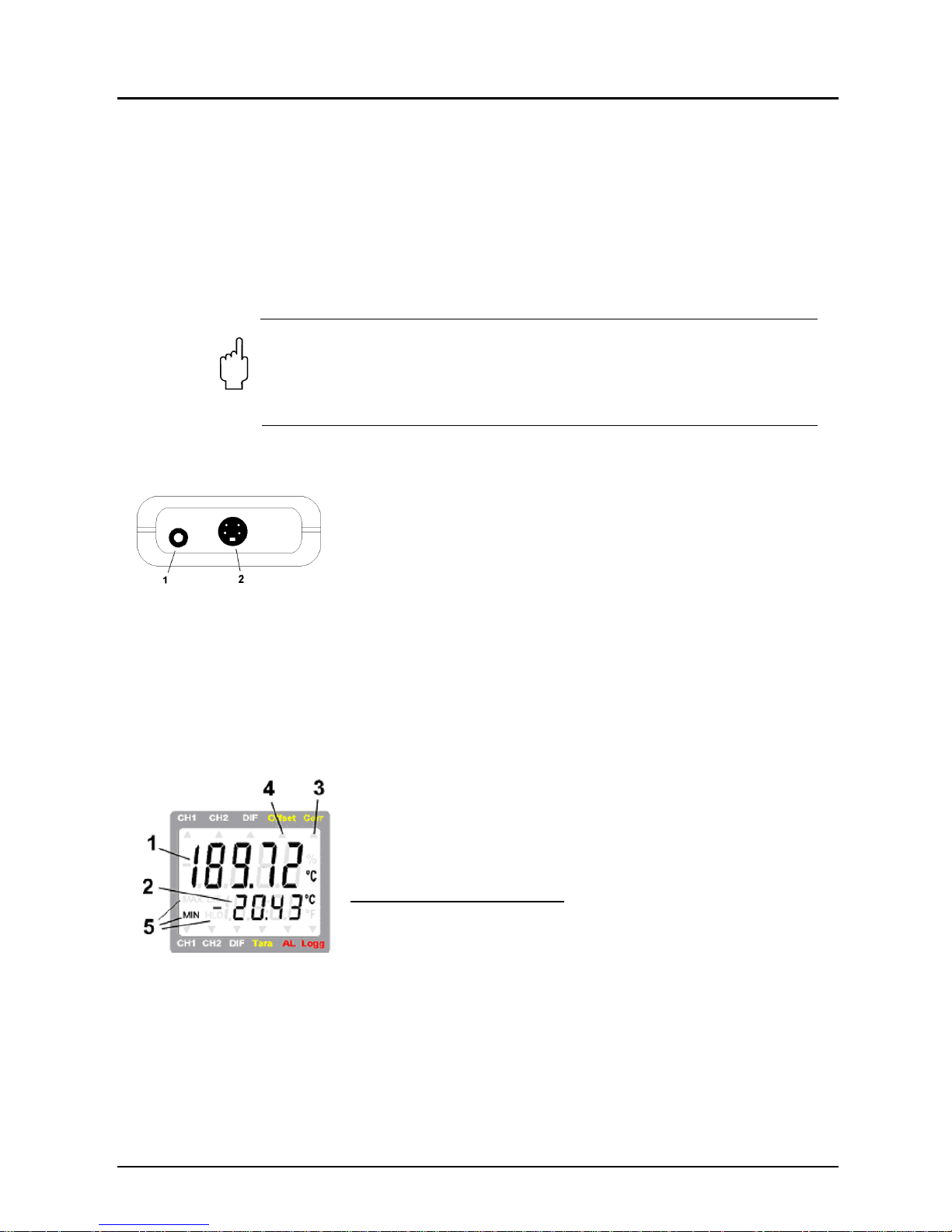
7.2 Connections
1 Output: Operation as interface: Connect to optically
isolated interface adapter
(accessory: HND-Z031 / HND-Z032)
Operation as analogue output: Connection via suitable
cable.
Attention: The output mode has to be configured and
influences battery life!
2. Probe connection Pt100 4-wire
3. The mains socket is located at the left side of the
instrument
7.3 Connections
1 = Main Display:
Currently measured
temperature
2 = Auxiliary Display:
Display of min, max or hold
values
Special display elements:
3 = Corr-arrow:
indicates that correction factor
is activated
4 = Offset-arrow:
indicates that zero point offset
(offset) is activated
5 = Min/Max/Hold:
shows if a min., max. or hold
value is displayed in the
secondary display
Page 7

HND-T105
HND-T105 K04/1016 page 7
7.4 Pushbuttons
key 1: On/Off key
key 4: Set/Menu
press (Menu) for 2 sec.: configuration
will activated
keys 2, 5: min/max when taking measurements:
press shortly: min. or max. measuring
value will be displayed
press for 2 sec.: the min. or max. value
will be deleted
up/down for configuration:
to enter values or change settings
key 6: Store/Quit:
- Measurement: Hold current measuring
value ('HLD' in display)
- Menu: Acknowledge setting, return to
measuring
key 3:
no function
7.5 Device Configuration
For configuration of the device press "Menu"-key (key 4) for 2 seconds, the first
menu will be shown. Choose between the individual values that can be set by
pressing the "Menu"-key (key 4) again. The individual values are changed by
pressing the keys "" (key 2) or "" (key 5).
Use key "Quit" (key 6) to leave configuration and to store settings.
7.5.1 'Unit': Selection of Temperature Unit °C / °F
°C:
All temperature values are in degrees Celsius
°F:
All temperature values are in degrees Fahrenheit
7.5.2 'Resolution': The Display Resolution
0.1°:
Resolution 0.1 °C
0.01°:
Resolution 0.01 °C
Auto:
Resolution is selected automatically
7.5.3 'Offset': Zero Displacement
-2.50 °C...2.50 °C
respectively
-4.50 °F...4.50 °F
The zero point of the measurement will be displaced
by this value to compensate for deviations in the
temperature probe or in the measuring device
oFF:
Zero displacement inactive (=0.0°)
Page 8

HND-T105
page 8 HND-T105 K04/1016
7.5.4 'Scal': Scale Correction
-2.000...2.000:
The scale of the measuring will be changed by this
factor to compensate for deviations in the temperature
probe or in the measuring device (factor is in %)
oFF:
Scale correction factor inactive (=0.000)
7.5.5 'Power.off': Selection of Power-Off Delay
1...120:
Power-off delay in minutes.
Device will be automatically switched off as soon as this
time has elapsed if no key is pressed/no interface
communication takes place
oFF:
Power-off function inactive (continuous operation, e.g.
mains operation)
7.5.6 'Out': Function of the Output
OFF:
No output function, lowest power consumption
SEr:
Output is serial interface
dAC:
Output is analogue output 0...1 V
7.5.7 'Address': Selection of Base Address when Output = Serial
Interface
01, 11, 21, ..., 91:
Base address of device for interface communication.
7.5.8 'dAC.0Volt': Output Offset When Output = Analogue Output
-200.0...850.0 °C
respectively
-328.0...1562.0 °F
Enter desired temperature value at which the
analogue output potential should be 0 V
7.5.9 'dAC.1Volt': Output Scale When Output = Analogue Output
-200.0...850.0 °C
respectively
-328.0...1562.0 °F
Enter desired temperature value at which the
analogue output potential should be 1 V
Hint: The settings will be set to the settings ex works, if key ‘Set‘
and ‘Store‘ are pressed simultaneously for more than 2 seconds.
Page 9

HND-T105
HND-T105 K04/1016 page 9
7.6 Some Basics of Precision Temperature Measuring
Probe Precision/Device Precision
The device is very precise (please refer to technical data). To be able to use
this high precision, the connected temperature probe has to be as precise as
possible, too. The following precision classes are available as a standard at
reasonable prices (Platinum resistor thermometers according to EN60751):
Class Error ranges
B ± (0.3 + 0.005 • |temperature|)
1/3 B (=1/3 DIN) ± (0.1 + 0.0017 |temperature|)
1/10 B (=1/10 DIN) ± (0.03 + 0,0005 • |temperature|)
A ± (0.15 + 0.002 • |temperature|)
error of device and probe
0
1
2
3
4
-200 0 200 400 600 800
T [°C]
error [°C]
B
1/3B
1/10B
A
GMH37xx
error of device and probe
0
0,2
0,4
0,6
0,8
1
1,2
-50 0 50 100 150
T [°C]
error [°C]
B
1/3B
1/10B
A
GMH37xx
Error over measuring range Error over range –50...150 °C
For applications demanding higher precision than given by this classes we
suggest to adjust the device to the used probe or to get a calibration certificate for
the device combined with the probe.
When demanding highest possible precision we suggest the usage of the
instrument HND-T205.
Attention: if an adjusted or calibrated probe is replaced, also the
adjustment or calibration certificate has to be renewed to maintain the
referring overall precision!
Be careful when buying third party temperature probes: Besides the
standard EN60751 there are some other obsolete or unusual standards on
the market. If such a probe has to be connected, the HND-T205 should be
used instead!
4-Wire-Measuring
When using resistance thermometers as the Pt100, a quite large measuring error
can be caused by inadequate cables and connections. Using 4wire measuring
avoids these kinds of errors mainly caused by unwanted resistances. It is
suggested to use suitable probes and extensions only. (For pin assignment
please refer to chapter 7.9 Probe pin assignment)
HND-T HND-T
Page 10

HND-T105
page 10 HND-T105 K04/1016
Heat loss caused by probe construction:
Especially when measuring temperatures which deviate very much from the
ambient temperature, measuring errors often occur if the heat loss caused by the
probe is not considered. When measuring fluids therefore the probe should be
emerged sufficiently deep and be stirred continuously. When measuring gases
the probe should also emerge as deep as possible in the gas to be measured
(e.g. when measuring in channel/pipes) and the gas should flow around the probe
at sufficient flow.
Measuring Surface Temperature
If temperature of the surface of an object has to be measured, one should pay
attention especially when measuring hot (or very cold) surfaces, that the ambient
air cools (or heats) the surface. Additionally the object will be cooled (or heated)
by the probe or the probe can have a better heat flow to the ambient temperature
as to the objects surface. Therefore specially designed surface probes should
be used. The measuring precision depends mainly on he construction of the
probe and of the physics of the surface itself. If choosing a probe try to choose
one with low mass and heat flow from sensor to handle. Thermally conductive
paste can increase the precision in some cases.
Allowable temperature Range of Probes
Pt100 Sensors are defined over a wide temperature range. Depending on probe
materials and sort of sensor (e.g. hybrid sensors, wire wound resistors...) the
allowable temperature ranges have to be considered. Exceeding the ranges at
least causes a wrong measuring, it may even damage the probe permanently!
Often it also has to be considered, that the temperature range is just valid for the
probe tube, (plastic-) handles can’t stand the same high temperatures. Therefore
the tube length should be selected long enough, so that temperature keeps low at
the handle.
Self Heating
The measuring current of the instrument is just 0.3 mA. Because of this
comparably low current practically now self heating effect has to be considered,
even at air with low movement the self heating is <= 0.01 °C.
Cooling by Evaporation
When measuring air temperature the probe has to be dry. Otherwise the cold due
to the evaporation causes too low measurings.
Page 11

HND-T105
HND-T105 K04/1016 page 11
7.7 Special Functions
7.7.1 Display Resolution
Standard setting: 'Auto', i.e. the device automatically switches over to the
optimum resolution between .01° and 0.01°.
If temperatures to be measured are near the switching threshold, a fixed
resolution may be better, e.g. for easy recording. In such a case please select the
optimum resolution manually.
7.7.2 Zero Displacement ('Offset')
A zero displacement can be carried out for the measured temperature:
temperature displayed = temperature measured - offset
Standard setting: 'off' = 0.0°, i.e. no zero displacement will be carried out.
Together with the scale correction (see below) this factor is mainly used to
compensate for sensor deviations. Unless the factor is set to 'off', the offset arrow
in the display shows an active zero displacement.
7.7.3 Scale Correction ('Scale')
The scale of the measuring can be influenced by this setting (factor is in %):
displayed temperature[°C] = measured temperature[°C] * (1+Scal/100)
respectively displayed temperature[°F] = (measured temperature [°F]-32 °F) *
(1+Scal/100) + 32 °F
Standard setting: 'off' =0.000, i.e. temperature is not corrected. Together with the
zero displacement (see above) this factor is mainly used to compensate for
sensor deviations.
Unless the factor is set to 'off', the Corr arrow in the display shows an active scale
correction.
7.7.4 Output
The output can be used as serial interface (for HND-Z031) or as analogue output
(0-1V). If none of both is needed, we suggest switching the output off, because
battery life then is extended.
7.7.4.1 Interface - Base Address ('Adr.')
By using an electrically isolated interface converter HND-Z031 or HND-Z032
(accessory) the device can be connected to a PC. In order to avoid transmission
errors, there are several security checks implemented (e.g. CRC).
The following standard software package is available for data transfer:
BUS-S20M Software for recording measurement data on a computer, for
instruments of the HND-series without logger function
Note: The measuring and range values read via interface are always in the
selected display unit (°C/°F)!
Page 12

HND-T105
page 12 HND-T105 K04/1016
Supported interface functions:
Code Name/Function Code Name/Function
0 read nominal value 200 read min. display range
3 read system status 201 read max. display range
6 read min. value 202 read unit of display
7 read max. value 204 read decimal point of display
12 read ID-no. 208 read channel count
174 delete min. value 214 read scale correction
175 delete max. value 215 set scale correction
176 read min measuring range 216 read zero displacement
177 read max measuring range 217 set zero displacement
178 read measuring range unit 222 read power-off time
179
read measuring range
decimal point
223 set power-off time
180 read measuring type 240 Reset
194 set display unit 254 read program identification
199 read meas. type in display
7.7.4.2 Analogue Output – Scaling with DAC.0 and DAC.1
With the DAC.0 and DAC.1 values the output can be rapidly scaled to Your
efforts.
Keep in mind not to connect low-resistive loads to the output, otherwise the
output value will be wrong and battery life is decreased. Loads up to ca 10kOhm
are uncritical.
If the display exceeds the value set by DAC.1, then the device will apply 1V to the
output.
If the display falls below the value set by DAC.0, then the device will apply 0V to
the output.
In case of an error (Err.1, Err.2, no sensor, etc.), the device will apply slightly
above 1V to the output.
plug wiring:
GND
Attention!
The 3
rd
contact has to
be left floating!
Only stereo plugs are
allowed!
+Uout
Page 13

HND-T105
HND-T105 K04/1016 page 13
7.8 Fault and System Messages
Display Meaning Remedy
low battery voltage, device will
continue to work for a short time
replace battery
If mains operation: wrong voltage
replace power supply, if fault continues to
exist: device damaged
low battery voltage replace battery
If mains operation: wrong voltage
Check/replace power supply, if fault
continues to exist: device damaged
No display
or
weird display
Device does
not react on
keypress
low battery voltage replace battery
If mains operation: wrong voltage
Check/replace power supply, if fault
continues to exist: device damaged
system error
Disconnect battery or power supply, wait
some time, re-connect
device defective return to manufacturer for repair
Err.1
Value exceeding measuring range
Check: Is the value exceeding the
measuring range specified? ->temperature
too high!
Wrong probe connected Check probe
sensor/cable defective -> replace
Err.2
Value below display range
Check: Is the value below the measuring
range specified? -> temperature too low!
Wrong probe connected Check probe
sensor/cable defective -> replace
Err.3
Value exceeding display range -> set resolution to 0.1° or Auto
Err.4
Value below display range -> set resolution to 0.1° or Auto
Err.7
system error return to manufacturer for repair
Page 14

HND-T105
page 14 HND-T105 K04/1016
7.9 Probe pin assignment
The device is constructed for the connection of a Pt100 4-wire probe. The
connection is being carried out as follows:
figure shows view upon probe jack pins
It is also possible to connect a 3- or 2-wire probe to the device. Please observe
that in consequence of the cable resistance an increased measuring fault will
occur. The connection of these probes should be carried out as follows:
3-wire connection 2- wire connection
Page 15

HND-T105
HND-T105 K04/1016 page 15
8. Technical Information
Measurement input: Pt 100,
4-wire, in accordance with DIN EN 60751
Measuring range: -199.99...+199.99 °C
or -200.0...+850.0 °C
(Fahrenheit values accordingly)
Accuracy: (at nominal temperature 25 °C)
≤ 0.03 °C in the range
-199.99...199.99 °C
≤ 0.1°C ±1 digit in the range
200.0...850.0 °C
Resolution: 0.01 °C or 0.1 °C
(0.01 °F or 0.1 °F)
Display: 2x 4 ½-digit LCD
Operating temperature: -25 to +50 °C
Storage temperature: -25 to +70 °C
Storage humidity: 0 to 95 % rH (non-condensing)
Probe connection: 4-pin shielded Mini-DIN plug
Output: 0-1 V,
freely scalable or serial interface
(via 3-pin jack, transformer on
RS232 or USB optional)
Power supply: 9 V-monobloc battery
(included in the scope of delivery),
external 10.5 -12 VDC via jack
Current consumption: approx. 1 mA
Material: housing made of impact-resistant
ABS plastic
Protection: IP 65, front
Dimensions: 142 x 71 x 26 mm (H x W x D)
Weight: approx. 155 g
Scope of functions
Minimum/maximum value memory
Hold function: »freezing« of the current value
Automatic-off function: 1...120 min (can be deactivated)
Zero point and increase entry: zero point and increase correction can be
entered digitally
Page 16

HND-T105
page 16 HND-T105 K04/1016
9. Order Codes
Order-no. Housing design
HND-T105
Pt 100 input, standard
9.1 PT100-measuring probe Class B
Probe type
Temperature/
response
time (t
90)
Order-no.
Immersion probe for liquids and gases,
4-wire
Rustproof V4A-tube, plastic handle, approx.
1m 4-pin PVC-cable, strain relief screw
connection, 4-pin Mini-DIN plug
-50...+400 °C
approx. 10 sec
HND-TF01
Immersion probe for liquids and gases,
4-wire
Like HND-TF01, but with
1.3 DIN Class B
(±0.1°C at 0°C)
-50...+400 °C
approx. 10 sec
HND-TF02
Immersion probe for liquids and gases,
4-wire
Like HND-TF01, but with
1.10 DIN Class B
(±0.03°C at 0 °C) and flexible sheath tube,
Ø 3 mm
-50...+400 °C
approx. 10 sec
HND-TF03
Insertion probe for soft, plastic media,
4-wire
Techn. data like HND-TF01, but with
needle-shaped knife-edge tip
-50...+400 °C
approx. 10 sec
HND-TF04
Insertion probe for soft, plastic
media, 4- wire
Like HND-TF04, but with
1.3 DIN Class B
(±0.1°C at 0°C)
-50...+400 °C
approx. 10 sec
HND-TF05
Immersion probe for liquids and gases,
4- wire
Rustproof V4A-tube, approx. 1 m 4-pin
PVC-cable, 4-pin Mini-DIN-plug
-50...+400 °C
approx. 10 sec
HND-TF06
Page 17

HND-T105
HND-T105 K04/1016 page 17
9.2 Accessories
Description Order no.
Plug power supply unit (220/240 V, 50/60 Hz), 10.5 V/10 mA
HND-Z002
Protective housing bag, nappa leather, with cut-out for round sensor connection
for HND-T105, HND-T205
HND-Z011
Protective housing bag, nappa leather, with cut-out for square sensor connection
for HND-T110, HND-T120, HND-T125
HND-Z013
Protective housing bag, nappa leather, with cut-out for two sensor connections
for HND-T115 and HND-T215
HND-Z014
Case with recess (275x229x83 mm)
HND-Z021*
Universal case with egg crate foam (275x229x83 mm)
HND-Z022*
Large case with recess (394x294x106 mm)
HND-Z023*
Interface converter on RS232, galvanically isolated
HND-Z031
Interface converter on USB, galvanically isolated
HND-Z032
Adapter RS232 converter on USB-interface
HND-Z033
Windows software for setting, data read out, and printing of the data of housings
of the HND-series with logger function
HND-Z034
Software for recording measurement data on a computer, for instruments of the HNDseries without logger function
BUS-S20M
Flat connector type N, free of thermoelectric voltage,
for connection of thermocouple element probe HND-TF21/22/23
HND-Z041
Additional probe accessories upon request
* Observe instrum ent dimensions
Page 18

HND-T105
page 18 HND-T105 K04/1016
10. EU Declaration of Conformance
We, KOBOLD Messring GmbH, Hofheim-Ts, Germany, declare under our sole
responsibility that the product:
Double/Differential Second Portable Thermometer HND-T105
to which this declaration relates is in conformity with the standards noted below:
EN 61326-1:2013
Electrical equipment for measurement, control and laboratory use - EMC
requirements - Part 1: General requirements
EN 50581:2012
Technical documentation for the assessment of electrical and electronic products
with respect to the restriction of hazardous substances
Also the following EC guidelines are fulfilled:
2014/30/EU Electromagnetic compatibility
2011/65/EU RoHS (category 9) industrial monitoring and control
instruments, compliant, no CE-marking for the transitional period until 2017
Hofheim, 13. Oct. 2016
H. Peters M. Wenzel
General Manager Proxy Holder
 Loading...