

Page 1
Operating Instructions
for
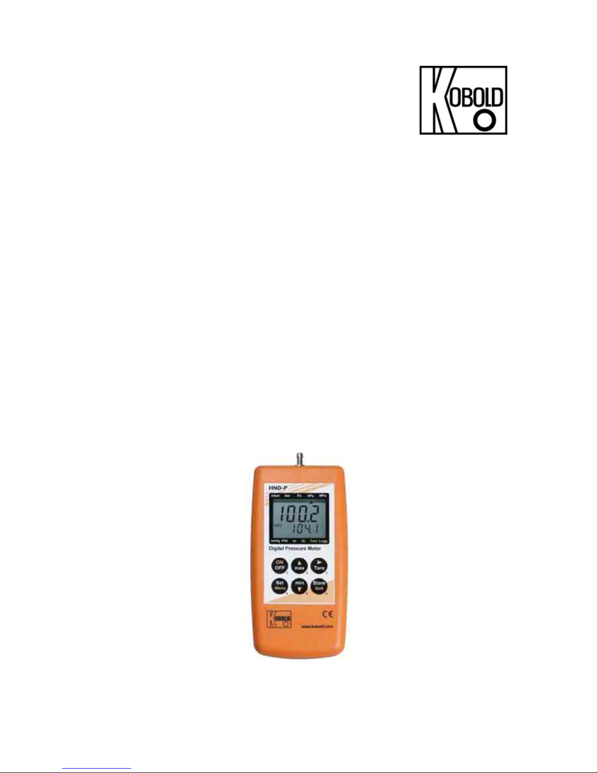
Handheld Digital Pressure Meter
with internal pressure sensor
Model: HND-P239
Page 2

HND-P239
page 2 HND-P239 K01/0307
1. Contents
1. Contents........................................................................................................2
2. Note ..............................................................................................................3
3. Instrument Inspection....................................................................................3
4. Regulation Use..............................................................................................3
5. Operating Principle........................................................................................4
6. Safety Requirements.....................................................................................4
7. Electrical Connection ....................................................................................5
8. Operation ......................................................................................................6
9. Configuration................................................................................................. 7
9.1 Different Kinds Of Measuring: „rAtE-Slo, -P.dEt, -FASt“ ......................8
9.2 Sea Level Correction ...........................................................................8
9.3 Averaging Function..............................................................................9
9.4 Power Off Time....................................................................................9
9.5 Address................................................................................................9
9.6 Alarm ...................................................................................................9
9.7 Real Time Clock ................................................................................10
10. Operation Of Logger ...................................................................................10
10.1 „Func-Stor“: Storing Single Measurements........................................10
10.2 „Func-CYCL“: Automatic Recording With Selectable Logger-Cycle-Time
11
11. The Serial Interface.....................................................................................13
12. Error And System Messages ......................................................................14
13. Calibration Services ....................................................................................14
14. Maintenance ...............................................................................................15
14.1 Battery Operation...............................................................................15
15. Technical Information..................................................................................15
16. Order Codes ...............................................................................................17
16.1 Accessories for HND-P ......................................................................17
17. Declaration of Conformance .......................................................................18
Manufactured and sold by:
Kobold Messring GmbH
Nordring 22-24
D-65719 Hofheim
Tel.: +49(0)6192-2990
Fax: +49(0)6192-23398
E-Mail: info.de@kobold.com
Internet: www.kobold.com
Page 3

HND-P239
HND-P239 K01/0307 page 3
2. Note
Please read these operating instructions before unpacking and putting the unit
into operation. Follow the instructions precisely as described herein.
The devices are only to be used, maintained and serviced by persons familiar
with these operating instructions and in accordance with local regulations
applying to Health & Safety and prevention of accidents.
When used in machines, the measuring unit should be used only when the
machines fulfil the EWG-machine guidelines.
3. Instrument Inspection
Instruments are inspected before shipping and sent out in perfect condition.
Should damage to a device be visible, we recommend a thorough inspection of
the delivery packaging. In case of damage, please inform your parcel service /
forwarding agent immediately, since they are responsible for damages during
transit.
Scope of delivery:
The standard delivery includes:
• Handheld Digital Pessure Meter with internal pressure sensor
model: HND-P239
• Operating Instructions
4. Regulation Use
Any use of the Handheld Digital Pressure Meter, model: HND-P239, which
exceeds the manufacturer’s specification may invalidate its warranty. Therefore,
any resulting damage is not the responsibility of the manufacturer. The user
assumes all risk for such usage.
Page 4
HND-P239
page 4 HND-P239 K01/0307
5. Operating Principle
The KOBOLD Handheld Digital Pressure Meters HND-P239 have an integrated
pressure sensor for absolute pressure measurement. The measuring device is
connected to the measuring point by means of a stable, metal connection on the
top of the housing and an optional plastic hose. This device design offers the
possibility of also displaying the barometric air pressure in relation to sea level
»zero«. In this case, air pressure is corrected by entering the height above
»zero« in meters. Naturally, these devices also have the minimum/maximum
value memory, a hold function, a tare function, automatic self-shut-off function,
and zero point adjustment. The HND-P239 devices also offer additional functions
like the logger function, peak value memory, minimum/maximum alarm, an
adjustable measuring cycle, and averaging.
6. Safety Requirements
This device has been designed and tested in accordance with the safety
regulations for electronic devices.
However, its trouble-free operation and reliability cannot be guaranteed unless
the standard safety measures and special safety advises given in this manual will
be adhered to when using the device.
1. Trouble-free operation and reliability of the device can only be guaranteed if
the device is not subjected to any other climatic conditions than those stated
under "Technical Information".
2. If the device is transported from a cold to a warm environment condensation
may cause in a failure of the function. In such a case make sure the device
temperature has adjusted to the ambient temperature before trying a new
start-up.
3. If device is to be connected to other devices the circuitry has to be designed
most carefully. Internal connection in third party devices (e.g. connection
GND and earth) may result in not-permissible voltages impairing or
destroying the device or another device connected.
Warning! If device is operated with a defective mains power
supply (e.g. short circuit from mains voltage to output voltage)
this may result in hazardous voltages at the device (e.g. at sensor
socket or interface).
Page 5

HND-P239
HND-P239 K01/0307 page 5
4. If there is a risk whatsoever involved in running it, the device has to be
switched off immediately and to be marked accordingly to avoid re-starting.
Operator safety may be a risk if:
- there is visible damage to the device
- the device is not working as specified
- the device has been stored under unsuitable conditions for a longer
period of time.
In case of doubt, please return device to manufacturer for repair or maintenance.
7. Electrical Connection
By operation with external power supply:
When using a power supply please note that operating voltage has to be 10.5 to
12 VDC. Do not apply overvoltage!!! Cheap 12V-power supplies often have
excessive no-load voltage. We, therefore, recommend using regulated voltage
power supplies. Trouble-free operation is guaranteed by our power supply HNDZ002. Prior to connecting the power supply to the mains make sure that the
operating voltage stated at the power supply is identical to the mains voltage.
Page 6
HND-P239
page 6 HND-P239 K01/0307
8. Operation
When switching on the device and the logger function is not off the time of the
integrated clock will shortly be displayed.
After changing the battery the clock-setting menu is activated automatically
(‚CLOC‘). Check the clock and adjust, if necessary (see chapter 9. Configuration).
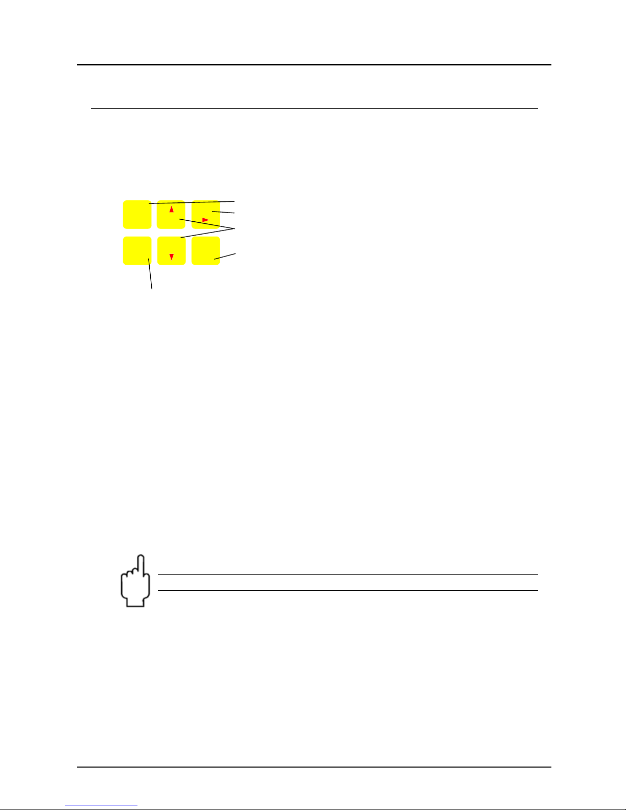
On-/Off-Switch
Tara: Calling of tara function, zero point adjustment
min/max: Showing the min- resp. max-memory in sec.
display
Store/Quit: Calling of hold function resp. calling of logger
functions
(please refer to chapter 10. “Operation Of Logger”)
Set/Menu: Calling of configuration
Max Memory: Pressing “max“ (key 2) shows the maximum of the measured
values. Pressing it again hides it. To clear the max memory press key „max“ for
>2 seconds.
Min Memory: Pressing “min“ (key 5) shows the minimum of the measured
values. Pressing it again hides it. To clear the min memory press key „min“ for >2
seconds.
Hold Function: By pressing “Store/Quit“ (key 6) the last measuring value
will be held in the secondary display. Pressing it again hides it. (only when logger
= ‚off‘).
Tare Function: By pressing ”Tara“ (key 3) the display will be set to 0. All
measurings from then on will be displayed relatively to the set tare value. When
tara function is activated, the arrow "Tara" appears in the display. To deactivate
tare function press ”Tara“ for >2 seconds.
Note: Activating/deactivating tara clears the max- & min-memories.
123
456
ON
OFF max
Tar a
Sto remin
Set
Menu Quit
Page 7

HND-P239
HND-P239 K01/0307 page 7
9. Configuration
To change device settings, press “Menu” (key 4) for 2 seconds. This will call the
configuration menu (main display: „SEt“).
Pressing key “Menu” changes between the menu, pressing “4“ (key 3) jumps to
the referring parameters, which can be selected with key “4“ (key 3).
The parameters can be changed with “5“ (key 2) or “6“ (key 5).
Pressing “Menu” again jumps back to the main configuration menu and saves
the settings.
“Quit” (key 6) finishes the configuration and returns to standard measuring
operation.
Menu Param. Values Meaning
‚Menu‘
4 5or6
Set Configuration: Generic Configuration
Unit
mbar,bar..
Unit: Unit of display
*
SL
oFF/on
Sea-Level: on or off
*
Alti
-2000..9999
Altitude: Input of altitude above sea level [m] (only if SL on)
*
Rate: Measuring rate (see chapter 9.1 Different Kinds Of
Measuring: „rAtE-Slo, -P.dEt, -FASt“)
*
Slo
Slow: measuring rate (4 Hz filtered, low power consumption)
*
FASt
Fast: measuring rate, filtered (>100 Hz)
*
rAtE
P.dEt
Peak detection: fast measuring rate, unfiltered (>100 Hz)
*
1-120
Averaging period in seconds, used by the averaging function
t.AVG
oFF
Averaging function deactivated
1-120
Auto Power-Off time in minutes
P.oFF
oFF
Auto Power-Off deactivated
SEt
ConF
Adr.
01,11..91
Base address of interface
Set Alarm: Settings Of Alarm Function
AL.
On
Alarm on, with horn-sound
no.So
Alarm on, without horn-sound
oFF
Alarm deactivated
AL.Lo
0 bar ... AL.Hi Min alarm rail (not when AL. oFF. Sensor-Min is the lower display
range of connected sensor)
SEt
AL.
AL.Hi
AL.Lo ...1.3 bar Max alarm rail (not when AL. oFF. Sensor-Max is the upper
display range of connected sensor)
Set Logger: Configuration Of Logger Function
*
Func
CYCL
Store: logger function, ‚cyclic logger’
*
Stor
Cyclic: logger function ‚individual value logger’
*
oFF
no logger function *
CYCL
1..3600
Cycle time of cyclic logger [seconds] *
SEt
LoGG
Lo.Po
on/oFF
Low-power logger with very low power consumption
(only for cyclic logger and slow measuring rate)
*
Set Clock: Setting Of Real Time Clock
CLOC
HH:MM
Clock: Setting of time hours: minutes
dAtE
TT.MM
Date: day. month
SEt
CLOC
YEAr
YYYY
Year:
Note! If the logger memory contains data already, the
menus/parameters marked with (*) can not be invoked! If these
should be altered the logger memory has to be cleared before! (key
6, please refer to. chapter 10. “Operation Of Logger”)
Page 8

HND-P239
page 8 HND-P239 K01/0307
9.1 Different Kinds Of Measuring: „rAtE-Slo, -P.dEt, -FASt“
Three different kinds of measuring pressure are supported. Two of them are
working with high measuring frequency of more than 100 measurings per second.
If one of them was chosen in the configuration (see above), this will be displayed
in the secondary display: „P.dEt“ or „FASt“.
9.1.1 rAtE-Slo: Standard Measuring
Measuring rate 4Hz, averaging and filter functions are active.
Application: Measuring of slowly changing or static pressures, e.g. measuring of
leak proofness, atmospheric pressure...
Highest accuracy, high noise immunity (EMI and unstable measuring signals),
low power consumption.
9.1.2 rAtE-P.dEt: Peak detection
Measuring rate >100Hz, the value is displayed unfiltered.
Application with logger function: Measuring of short pressure peaks or fast
changing pressures with a resolution of <10ms. The cyclic logger function records
the arithmetic mean value, the highest and the lowest peak of the referring time
interval.
Attention: higher power consumption, measuring is sensitive to noise (EMI,..).
9.1.3 rAtE-FASt: Fast filtered measuring
Measuring rate >100Hz, the value is filtered slightly (higher noise immunity than
P.dEt, small peaks will be filtered out), apart from that identical behaviour like
P.dEt.
9.2 Sea Level Correction
The device displays the absolute pressure measured at the sensor. This is not
necessarily the same like the values given by weather stations! The weather
stations‘ values are giving the pressure at sea level. Usually the sensor is placed
above sea level and therefore, if the value at sea level(zero) is to be measured,
the pressure loss resulting from the actual level above sea level has to be
considered! To correct the measuring display activate the „Sea-Level-Function“
(SL, please refer to chapter 9. “Configuration”). Then enter the altitude above sea
level of the sensor‘s location in meters (Alti, please refer to chapter 9.
Configuration). When activated, the display shows the SL-arrow and the device
displays the pressure value at sea level.
Page 9

HND-P239
HND-P239 K01/0307 page 9
9.3 Averaging Function
The averaging function concerns the display values (LCD and interface). It is
completely independent from the averaging of the logger function, please don’t
mix them up!
The averaging integrates the measuring values during a selectable period of time
and then calculates the average display value. It is independent from the selected
kind of measuring (slow, fast, peak detect)
As long as not enough values are collected (selected averaging time) to calculate
a average value, the upper display shows “----“, the lower display a ‘countdown‘.
During an active low-power-logging procedure the averaging is always
deactivated.
Function of min/max-value memory during averaging:
• If averaging is activated and slow measuring is selected (rAtE-Slo),
the min-/max-value memory refers to the average display value.
• If averaging is activated and fast measuring is selected (rAtE-FASt or P.dEt) ,
the min-/max-value memory refers to the internal measured values (fast peaks
can be detected).
9.4 Power Off Time
If there won’t be pressed any key and no interface communication takes place for
the time of the power off time setting (P.Off), the device will be switched off
automatically to save battery power.
If P.oFF = oFF then the automatic switch off is deactivated.
9.5 Address
Up to 10 devices of the GMH3xxx- handheld-family can be connected to a serial
interface at once (depending on interface converter, e.g. GRS3105: 5 devices).
To get access to each device the base addresses of the devices have to be
different. For example choose 01 for the first, 11 for the second device and so on.
See also chapter 11. “The Serial Interface”.
9.6 Alarm
There are three possible settings: Alarm off (AL. oFF), on with horn sound (AL.
on), on without horn sound (AL. no.So).
Following conditions will display an alarm, when the function is activated (on or
no.So):
- Value is below lower (AL. Lo) or above upper alarm rail (AL.Hi).
- Sensor error (Sens Erro)
- Low battery (bAt)
- Fe 7: System error (always with sound)
In case of an alarm and when polling the interface the prio-flag is set in the
returned interface message.
Page 10

HND-P239
page 10 HND-P239 K01/0307
9.7 Real Time Clock
The real time clock is used for the logger function: Recorded values are also
containing the point of time, when they were measured. Please check the settings
when necessary.
If the battery was replaced the referring menu ‚CLOC‘ will automatically be
started.
10. Operation Of Logger
The device supports two different logger functions:
„Func-Stor“:
each time when „store“ (key 6) is pressed a measurement will be recorded.
„Func-CYCL“:
measurements will automatically be recorded each interval, which was set in the
logger menu ‚CYCL‘ until the logger will be stopped or the logger memory is full.
The recording is started by pressing „Store“ 2 seconds.
The logger records 3 measurement results each time:
Current or mean value (depending on logger setting, see below), min peak and
max peak.
Min and max peak are the minimum resp. the maximum of the measured values
since the last recording.
Using them allows f.e. analysis of fluctuating pressures.
For the evaluation of the data the software HND-Z034 has to be used. The
software also allows easy configuration and starting of the logger.
When the logger is activated (Func Stor or Func CYCL) the hold function is no
more available, the key 6 is solely used for the operation of the logger functions.
10.1 „Func-Stor“: Storing Single Measurements
Each time when „store“ (key 6) is pressed a measurement and its time stamp will
be recorded.
The recorded data can be viewed either in the display (when calling the
configuration an additional menu „REAd LoGG“ is displayed, see below) or by
means of the interface and a PC with GSOFT3050-software.
Max. number of measurings: 99
A measuring contains:
- current measuring value at the time of recording
- min peak, max peak since the last recording
- - time and date of the recording
Page 11

HND-P239
HND-P239 K01/0307 page 11
After each recording „St. XX“ will be displayed for a short time. XX represents the
number of the recording.
If logger memory contains recordings already:
When „Store“ is pressed for 2 seconds, the choice for clearing the logger memory
will be displayed:
The selection can be made by “5“ (key 2) and “6“ (key 5). "Quit" (key 6) enters
the choice.
If the logger memory is full, the display will show:
Viewing Recorded Measurements
Within the „LoGG Stor“ function the measurements can be viewed directly in the
display not only by means of a computer (like at „Func CYCL“): press 2 seconds
„Set“ (key 4): The first menu displayed now is „rEAd LoGG“ (read logger data).
After pressing “4“ (key 3) the measurement recorded last will be displayed,
changing between the different values referring to the measurement also is done
by pressing “4“.
Changing the measurement is done by pressing the keys “5“ or “6“.
10.2 „Func-CYCL“: Automatic Recording With Selectable
Logger-Cycle-Time
The Logger-Cycle-Time is settable (please refer to Configuration). For example
„CYCL“ = 60: A measuring is recorded after each 60 seconds.
When the slow measurement "rAtE-Slo" is chosen, additionally a low power
function is available: „Lo.Po“.
If „Lo.Po“ is on, the device only will take a measurement at the point of time of the
recording. In between the recordings the measuring shuts down. This decreases
the power consumption enormously and therefore is recommended e.g. for long
time recordings where no mains adapter is available.
Max. number of measurings: 9999
Cycle time: 1...3600 seconds (=1h), selectable in the configuration
A measurement comprises of:
by slow measurements (rAtE Slo):
• current measuring value at the time of recording
• min peak, max peak since the last recording
by fast measurements (rAtE FASt,P.dEt)
Clear all
recordings
Clear the last
recording
Clear nothing
(Cancel menu)
Page 12

HND-P239
page 12 HND-P239 K01/0307
• arithmetic mean value since the last recording
• min peak, max peak since the last recording
Starting a recording:
By pressing "Store" (key 6) for 2 seconds the recording will be initiated. After that
the display shows ‘St.XXXX‘ for a short time whenever a measuring is recorded.
XXXX is the number of the measuring 1..9999.
If the logger memory is full, the display will show: The recording
automatically will be stopped.
If Low-Power-Logger-Function „Lo.Po = on“ the device switches itself off as soon
as the memory gets filled.
Stopping the recording manually:
By pressing "Store" (key 6) the recording can be stopped manually. Then the
following choice appears:
The selection can be made by “5“ (key 2) and “6“ (key 5). "Quit" (key 6) enters
the choice.
Note: If you try to switch off the instrument in the cyclic recording
operation You will be asked once again if the recording is to be
stopped. The device can only be switched off after the recording
has been stopped!
The Auto-Power-Off-function is deactivated during recording!
Clear Recordings:
When „Store“ is pressed for 2 seconds, the choice for clearing the logger memory
will be displayed:
The selection can be made by “5“ (key 2) and “6“ (key 5). "Quit" (key 6) enters
the choice.
Stop the
recording
Do not stop the
recording
Clear all
recordings
Clear nothing (cancel menu)
Page 13

HND-P239
HND-P239 K01/0307 page 13
11. The Serial Interface
With an electrically isolated interface converter HND-Z031 (accessories) the
device can be directly connected a RS232 interface of a computer (HND-Z032
complies with USB-interface). To avoid transmission errors, there are several
security checks implemented (CRC).
The following standard software packages are available:
HND-Z034: Operation and read out of logger function, data display in
diagrams and tables
The device has 3 channels:
Channel 1: current measuring value (base address)
Channel 2: min peak (please refer to chapter 10. Operation Of Logger)
Channel 3: max peak (please refer to chapter 10. Operation Of Logger)
Note! The measuring-/ alarm- and display range values read back
from the interface are always in the selected measurement unit
(mbar, bar...)!
Supported functions:
Channel Code Name/Function Channel Code Name/Function
1 2 3 1 2 3
x x x 0 Read measurement value x x x 199 Read kind of measuring of display
x x x 3 Read system state x x x 200 Read min display range
x 6 Read min memory x x x 201 Read max display range
x 7 Read max memory x x x 202 Read display range - unit
x x x 12 Read ID number x x x 204 Read display range – decimal point
x 22 Read min alarm rail (AL. - AL.Lo) x 208 Read # of channels
x 23 Read max alarm rail (AL. - AL.Hi) x 220 Read altitude (only abs. press sensors)
x 221 Set altitude (only abs. press sensors)
x 222 Read power off time (Conf-P.oFF)
x 223 Set power off time (Conf-P.oFF)
x x x 224 Logger: Read data of CYCL- Logger
x 32
Read configuration flag
BitAlarmOn:1; BitAlarmSound:3;
BitCorrectToSealevel:32 (only abs. press. Sensors);
BitPeakDetection:33; BitFastFiltered:34;
BitLoggerOn:50; BitCyclicLogger:51;
BitLowPowerLogger:52
x 225 Logger: Read cycle time (LoGG - CYCL)
x 102 Set min alarm rail (AL. - AL.Lo) x 226 Logger: set cycle time (LoGG - CYCL)
x 103 Set max alarm rail (AL. - AL.Hi) x 227 Logger: start recording
x 160 Set configuration flag (refer to 32) x 228 Logger: Read # of recordings made
x 174 Clear min memory x 229 Logger: Read state
x 175 Clear max memory x 231 Logger: Read stop time
x x x 176 Read min measuring range x 233 Read real time clock (CLOC)
x x x 177 Read max measuring range x 234 Set real time clock (CLOC)
x x x 178 Read measuring range – measuring unit x 236 Read logger memory size
x x x 179 Read measuring range – decimal point x 240 Reset
x x x 180 Read kind of measuring of sensor x 254 Program version
x 194 Set display unit x 260 Logger: read data of STOR Logger
Page 14

HND-P239
page 14 HND-P239 K01/0307
12. Error And System Messages
Display Meaning What to do?
Low battery power, device will only
continue operation for a short period of
time
Replace battery
Battery empty Replace battery
Mains operation without battery: wrong
voltage
Check power supply, replace it
when necessary
Logger data are read by the interface When transfer completed the device
will automatically return to normal
measuring display, no remedy
necessary
Battery empty Replace battery
Mains operation without battery: wrong
voltage or polarity
Check power supply, replace it when
necessary
System error Disconnect battery and power
supplies, wait shortly, then reconnect
No display
or confused
characters,
device does
not react on
keypress
Device defective Return to manufacturer for repair
Measured value above allowable range Check: pressure above 1300 mbar?
-> measuring value to high
Err.1
Sensor defective Return to manufacturer for repair
Measured value below allowable range -> measuring value to low
Err.2
Sensor defective Return to manufacturer for repair
Err.4
Value is too low to be displayed, tara is
set
Check: display below -2000 (tara?)?
Err.9
Measured value far out of allowable
range
Check: pressure not within sensor
range?
Err.7
System error Return to manufacturer for repair
13. Calibration Services
Calibration certificates – DKD-certificates – other certificates:
If device should be certificated for its accuracy, it is the best solution to return it to
the manufacturer.
Only the manufacturer is capable to do efficient recalibration if necessary to get
results with highest accuracy!
Page 15

HND-P239
HND-P239 K01/0307 page 15
14. Maintenance
14.1 Battery Operation
If and ´bAt´ are shown in the secondary display, the battery has been used up
and needs to be replaced. The device will, however, operate correctly for a
certain amount of time. If ´bAt´ is shown in the upper display the voltage is too
low to operate the device; the battery has been completely used up.
The battery has to be taken out, when, the device is stored above 50°C.
We recommend to take out battery if device is not used for a longer
period of time!
15. Technical Information
Measuring range: 0 to 1300 mbar
Accuracy: ±0,2 % F.S.
(hysteresis and linearity)
±0.4 % F.S.
(temperature dependency 0-50 °C)
Resolution: 1 mbar
Pressure units: mbar, bar, kPa, MPa, mmHg, PSI, m
(switchable)
Overload: max. 4 bar absolute
Measuring input: by means of a metal-hose stem
Sensor: piezo-resistive absolute pressure sensor,
for air or non-corrosive and
non-ionising gases and liquids,
not for water!
Display: 2 x 4-digit LC-displays
Operating temperature: 0…50 °C
Storage temperature: -20…+70 °C
Relative humidity: 0...95 % r.H. (non-condensing)
Output: serial interface
(via 3-pin jack, transformer on
RS232 or USB optional)
Power supply: 9V-monobloc battery
(included in scope of delivery),
external 10.5 - 12VDC via jack
Current consumption: max. 3 mA (HND-P239)
Materials: housing made of impact-resistant ABS plastic
Protection: IP65, front side
Dimensions: 142 x 71 x 26 mm (L x W x D)
Weight: approx. 160g
!
Page 16

HND-P239
page 16 HND-P239 K01/0307
Scope of functions:
• Min-/Max-value memory
• Hold function: »freezing« of the current value
• Automatic-off function: 1...120 min (can be deactivated)
• Zero point adjustment via keyboard possible
• Tare function: Display, minimum/maximum values are set to zero
• Battery change notification
Additional functions for the HND-P239:
• Minimum/maximum alarm can be deactivated
• Alarm (3 alarm settings)
Off: Alarm function inactive
On: Alarm notification via display, internal horn
and serial interface
No Sound: Alarm notification only via display
and interface
• Averaging
• Peak value memory unfiltered pressure peaks ≥ 10 msec
• Adjustable measuring cycle:
»slow« 4 measurements/sec
»fast« ≥ 100 measurements/sec (filtered)
»peak-detect« ≤ 100 measurements/sec
• Power saving mode in the measuring cycle »slow«
• Real-time clock: current time
• Logger functions:
Manual: 99 datasets
Cyclic: 9999 datasets
Adjustable cycle time: 1sec...1h
Page 17

HND-P239
HND-P239 K01/0307 page 17
16. Order Codes
Order-No. Design
HND-P 239
1x pressure sensor input, with additional functions
(see Technical Information)
16.1 Accessories for HND-P
Order-No. Description
HND-Z002
Plug power supply unit (220/240 V, 50/ 60 Hz), 10,5 V/10 mA
HND-Z011
Equipment protective housing bag, nappa leather, with 1 cut-out for
round sensor connection
HND-Z012
Equipment protective housing bag, nappa leather, with 2 cut-outs for
round sensor connection of the HND- series with logger function
HND-Z021
Case with recess (275 x 229 x 83 mm)
HND-Z022
Universal case with egg crate foam (275 x 229 x 83 mm)
HND-Z023
Large case with recess (394 x 294 x 106 mm)
HND-Z031
Interface converter on RS232, galvanically isolated
HND-Z032
Adapter RS232 converter on USB- interface
HND-Z033
Interface converter on USB, galvanically isolated
HND-Z034
Windows software for setting, data read-out, and printing of the data of
housings of the HND- series with logger function
HND-Z081
Double nozzle for hose
6
/4 on hose 6/
4
HND-Z082
Hose clamp for hose
6
/
4
HND-Z083
Adapter made of brass for G ¼ internal threads on hose
6
/4
HND-Z084
PVC-hose (5 bar), 6 mm external / 4 mm internal
HND-Z085
PE-hose (10 bar), 6 mm external / 4 mm internal
HND-Z086
PU-hose (9 bar), 6 mm external / 4 mm internal
HND-Z087
PA-hose (25 bar), 6 mm external / 4 mm internal
Additional accessories on request.
Page 18

HND-P239
page 18 HND-P239 K01/0307
17. Declaration of Conformance
We, KOBOLD Messring GmbH, Hofheim-Ts, Germany, declare under our sole
responsibility that the product:
Handheld Digital Pressure Meter
with external pressure sensor Model: HND-P239
to which this declaration relates is in conformity with the standards noted below:
Also the following EEC guidelines are fulfilled:
93/38/EEC, 2004/108/EC Electromagnetic compatibility
73/23/EEC, 93/68 EEC Low voltage guideline (for usage of the external
power supply HND-Z002)
Hofheim, 28. Jul. 2005
H. Peters M. Wenzel
General Manager Proxy Holder
 Loading...