

Page 1
Operating Instructions
for
Digital Thermometers
Model: DTM
Page 2

DTM
page 2 DTM K01/0117
1. Contents
1.
Contents ........................................................................................................ 2
2. Note .............................................................................................................. 3
3. Instrument Inspection .................................................................................... 3
4. Regulation Use .............................................................................................. 3
5. Operating Principle ........................................................................................ 4
6. Mechanical Connection ................................................................................. 5
7. Electrical Connection .................................................................................... 5
8. Operation ...................................................................................................... 7
9. Key Function ................................................................................................. 8
10.Technical Information .................................................................................... 9
11.Order Codes ............................................................................................... 10
12.Maintenance ............................................................................................... 10
13.Dimensions ................................................................................................. 10
14.EU Declaration of Conformance .................................................................. 13
15.Annex .......................................................................................................... 14
Manufactured and sold by:
Kobold Messring GmbH
Nordring 22-24
D-65719 Hofheim
Tel.: +49(0)6192-2990
Fax: +49(0)6192-23398
E-Mail: info.de@kobold.com
Internet: www.kobold.com
Page 3

DTM
DTM K01/0117 page 3
2. Note
Please read these operating instructions before unpacking and putting the unit
into operation. Follow the instructions precisely as described herein.
The devices are only to be used, maintained and serviced by persons familiar
with these operating instructions and in accordance with local regulations
applying to Health & Safety and prevention of accidents.
When used in machines, the measuring unit should be used only when the
machines fulfil the EC-machine guidelines.
3. Instrument Inspection
Instruments are inspected before shipping and sent out in perfect condition.
Should damage to a device be visible, we recommend a thorough inspection of
the delivery packaging. In case of damage, please inform your parcel service /
forwarding agent immediately, since they are responsible for damages during
transit.
Scope of delivery:
The standard delivery includes:
Digital Thermometers, model: DTM
Operating Instructions
4. Regulation Use
Any use of the Digital Thermometers, model: DTM, which exceeds the
manufacturer’s specifications, may invalidate its warranty. Therefore, any
resulting damage is not the responsibility of the manufacturer. The user assumes
all risk for such usage.
Page 4
DTM
page 4 DTM K01/0117
5. Operating Principle
Digital thermometers with intelligent electronics serve to display, monitor, control
and transmit temperatures in production processes and equipment.
The new device series DTM... is remarkable for its easy operation and adaptation
to the most demanding measurement applications.
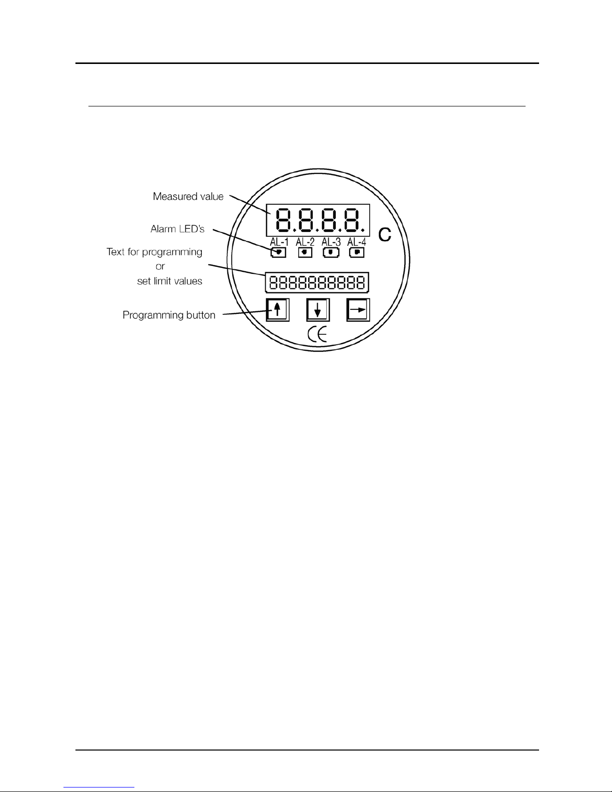
A 4-segment 14 mm LED display provides clearly visible indication, the device is
programmed with three arrow keys beneath the lower back-lit LCD display.
The devices are fitted with an analogue output as standard. Other interfaces are
available as options. Up to four limit values can be adjusted in the relay version.
The temperature to be measured is sensed by a platinum resistance thermistor
and converted by the electronics to an analogue signal proportional to the
temperature. The digital thermometer can be supplied in a compact shaft version
for a maximum indicating range of a 200°C. Above 200°C the temperature sensor
should be connected externally to the basic device with a cable.
Page 5

DTM
DTM K01/0117 page 5
6. Mechanical Connection
Before installation:
Be sure the maximum allowable working pressure and temperature specified
for the unit are not exceeded.
Make sure there are no packaging residues left inside the unit.
Installation:
Make sure the device into which the thermometer is to be installed has been
depressurised.
Mount the DTM where it may be easily connected according to applicable
codes and standards.
Do not screw in the unit using its housing, but rather on its hexagon (size 24
spanner).
If feasible, check the connection between the unit and the process or plant for
leaks as early as after mechanical installation.
7. Electrical Connection
Attention! Make sure that the voltage values of your system
correspond with the voltage values of the Digital Thermometers.
Make sure that the electrical supply wires are de-energized.
Remove the plastic cover
from the unit’s rear.
Insert the cable in the screw
terminal, and fix. Make sure
the PG connection is tight.
Pull off the terminal strip and
connect the cable as shown
in the terminal diagram.
Page 6
DTM
page 6 DTM K01/0117
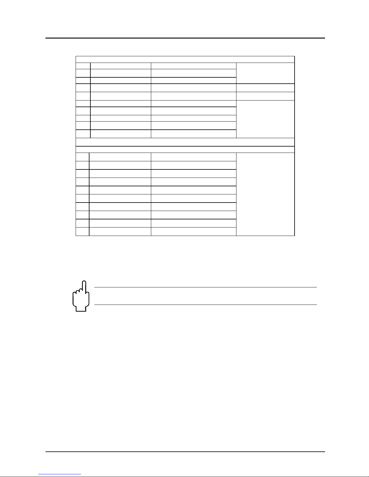
X103
1 Supply + channel-2 /external (option)
For external sensor
4 to 20 mA only
2 Not used
3 Supply - channel-2 /external (option)
4 Not used
5 Not used
6 Supply + channel-1 /external (option)
for external sensor
4 to 20 mA only
7 Not used
8 Supply - channel-1 /external (option)
9 Not used
10 Not used
X113
1 Not used
2 Not used
3 Not used
4 Data transfer RS 232 (option)
5 Data receive RS 232 (option)
6 Earth RS 232 (option)
7 Earth output (-)
8 Signal output (+)
9 Earth supply (-)
10 24 VDC supply (+)
Plug the terminal strip onto the plug base on the unit.
Slip on the plastic cap, and bolt in place.
Be sure the packing ring inside the plastic cap fits tightly.
Attention! Incorrect wiring will lead to damage of the unit’s
electronics.
Page 7

DTM
DTM K01/0117 page 7
8. Operation
The various functions and parameters are distributed over three (3) levels.
LEVEL 0- operator level
This level is accessible to anyone (without a password).
It will be possible to set the following functions if they are enabled.
Zero balance of the display unit (inPUt ¯ S-ZEro),
Servicing (SErVicE), always enabled:
View serial number (SErVicE ¯ n),
Enter master password to view passwords,
(SErVicE MAStr) (see 10.3),
Limit contacts (option) (rELAiS 1-4) :
Switching points (rELAiS 1-4 SPt1-4),
Switching point hysteresis (rELAiS 1-4 HyS1-4),
Switching point lag time (rELAiS 1-4 dEL1-4),
Additional functions (option):
Scaling of analogue output (outZP),
Scaling of display unit (diSPLAY),
Setting the peak memory (Pdu),
Setting the relay rotation (rotAtE),
Setting the RS 232 interface (S232).
All the menu items of LEVEL 1 and LEVEL 2 (except for the servicing menu item)
may be enabled or blocked respectively for LEVEL 0.
LEVEL 1- master level
Access to this level is via password. All the functions of level 1 (for level 0) can be
enabled or blocked respectively on this level. Settings of LEVEL O may also be
made on LEVEL 1 (if LEVEL 0 is blocked, for example).
Additionally, the following functions are available:
Servicing (SErVicE):
Displaying the dialogue display in operating mode (SErVicE SEE-Lcd),
Changing the password for LEVEL 1 (SErVicE PS-1).
LEVEL 2- additional function level
Access to this level is via LEVEL 1 after entering a password.
All additional functions available as options may be blocked or enabled
respectively on this level. Settings for additional functions may also be made on
LEVEL 2 (if LEVEL 0 is blocked, for example).
In addition, the following function is available:
Servicing (SErVicE):
Changing the password for LEVEL 2 (SErVicE PS-2).
Page 8

DTM
page 8 DTM K01/0117
9. Key Function
The menu items are shown in an annexed schematic.
In measurement mode
On the levels
In the functions
A
ccess to control levels
Access to menu items
Access to the functions of the
Various menu items
Exit the level and return to
operating mode
Access to setting (r.h. digit is flashing)
Next digit with an overflow to the right
One digit down
One digit up
Reject this setting; reload previous value
and return to selected function.
Confirm setting and go to next function of
m
enu ite
m
Page 9

DTM
DTM K01/0117 page 9
10. T echnical Information
Sensor: Pt 100, class B
Casing: diameter: 100 mm
material stainless steel,
rear made of polyamide,
front side made of PAVG30 and polyester film,
Electrical connection: terminal blocks, PG cable gland,
Protection: IP 65 acc. to DIN 40 050, IEC 529
Probe: diameter 8 mm (others upon request),
material stainless steel 1.4571,
Probe length: acc. to customer specifications, min. 50 mm
Process connection: stainless steel 1.4571
Indicating range: - 30 to + 50 to 0 to 400 °C
Accuracy class: 0.5
Analogue output: 0 to 20 mA, 4 to 20 mA, 0 to 10 V (all 3-wire)
Max. load/burden: 500 for current output
500 for voltage output
Accuracy: typically ± 0.3 % (limit point setting)
(acc. to DIN 16 086)
Repeatability: ± 0.1 %
Limit value relay: Switching points adjustable as required
Switching hysteresis adjustable as required
Switching delay adjustable from 0.01 to 99.99 s
Max. switching voltage: 250 VAC, 220 VDC,
Max. switching current: 3 A
Max. breaking capacity: 50 VA, 60 W
Response time:
Display and output signal 100 ms
Relay output 30 ms
Supply: 15 to 30 VDC
Service environment:
Ambient temperature: -20 to +60 °C
Storage temperature: -40 to +70 °C
Functions (standard):
Output signal
setting of scaling and delay
Display
setting of scaling, decimal point and delay
Functions (optional):
Peak memory with effect on display, output, relay,
internal reset via adjustable timer, keyboard or RS 232
Serial interface RS 232
2 external probes (differential temperature)
Higher temperatures (on request)
Page 10

DTM
page 10 DTM K01/0117
11. Order Codes
12. Maintenance
This unit will require no maintenance or servicing unless the medium is dirty.
13. Dimensions
Page 11

DTM
DTM K01/0117 page 11
Page 12

DTM
page 12 DTM K01/0117
Page 13

DTM
DTM K01/0117 page 13
14. EU Declaration of Conformance
We, KOBOLD Messring GmbH, Hofheim-Ts, Germany, declare under our sole
responsibility that the product:
Digital Thermometers Model: DTM
to which this declaration relates is in conformity with the standards noted below:
EN 61000-6-3:2011
Electromagnetic compatibility (EMC) - Part 6-3: Generic standards - Emission
standard for residential, commercial and light-industrial environments
EN 61000-6-2:2006
Electromagnetic compatibility (EMC) - Part 6-2: Generic standards - Immunity for
industrial environments
EN 61010-1:2011
Safety requirements for electrical measuring, control and laboratory instruments –
Part 1: General requirements
EN 60529:2014
Degrees of protection provided by enclosures (IP Code)
Also the following EU guidelines are fulfilled:
2014/30/EU EMC Directive
2014/35/EU Low Voltage Directive
2011/65/EU RoHS
Hofheim, 12. Jan. 2017
H. Peters M. Wenzel
General Manager Proxy Holder
Page 14

DTM
page 14 DTM K01/0117
15. Annex
Page 15

DTM
DTM K01/0117 page 15
Page 16

DTM
page 16 DTM K01/0117
Page 17

DTM
DTM K01/0117 page 17
 Loading...