

Page 1
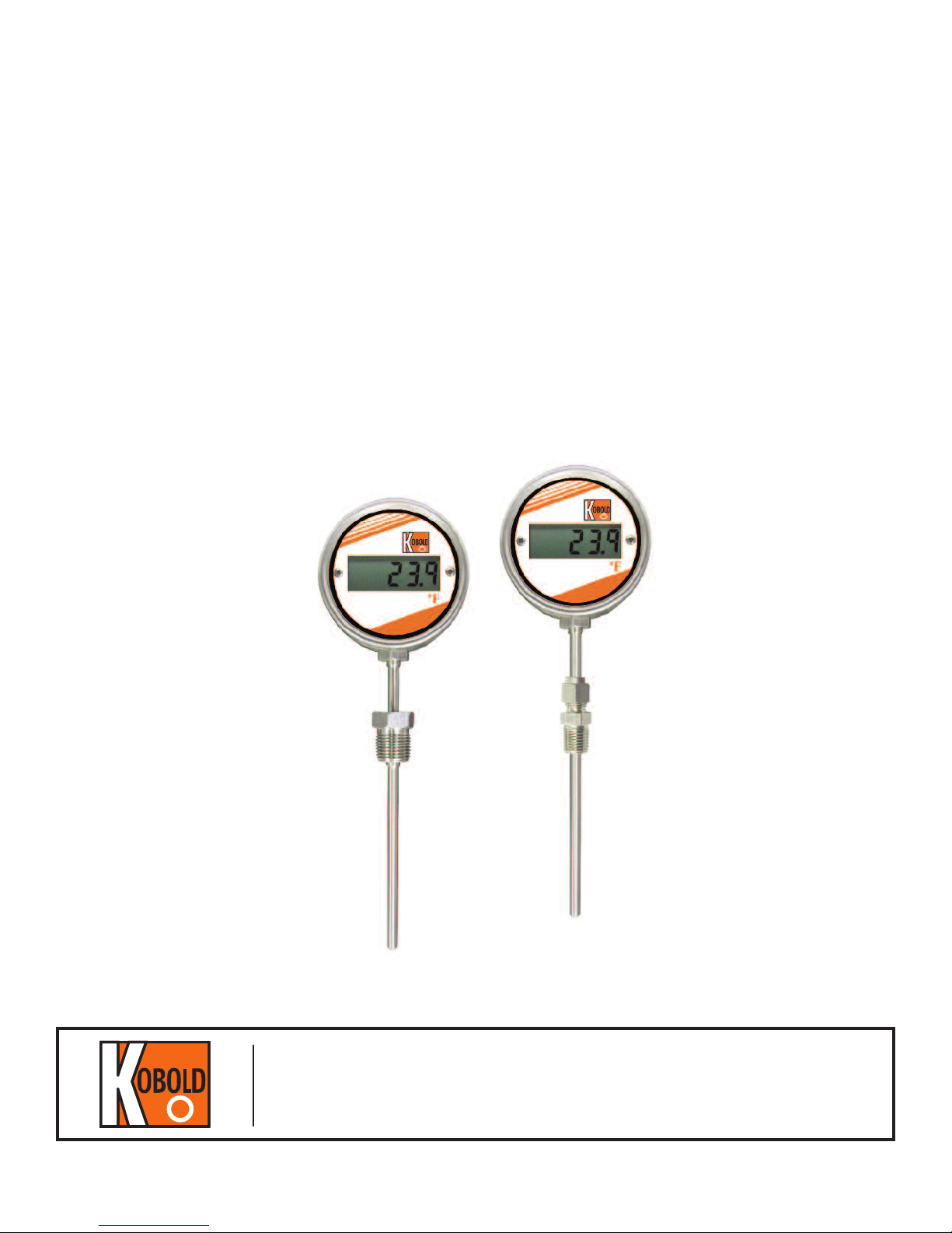
DTB Series
Battery Powered
Digital Thermometer
USER MANUAL
KOBOLD Instruments Inc.
1801 Parkway View Drive
Pittsburgh, PA 15205
Phone: 412-788- 28 30 Fax: 412-788- 48 90
www.koboldusa.com
Rev. 2-11/2013
Page 2

1. Description
F
F
F
F
F
F
The DTB series Digital Temperature Gauges are a complete solution for most industrial temperature monitoring
and temperature indicating applications. Of high quality
construction, these gauges features a large 4-digit LCD
display. They are designed for optimum accuracy and
performance. The series DTB are an ideal replacement
for bi-metal, liquid bulb and gas thermometers. They
are also a suitable replacement for Mercury reduction
programs.
The DTB arrives factory calibrated. No costly field
calibration is required.
Housing, probe and fitting material is all fabricated from
stainless steel 316. The DTB is rated to NEMA 4X ( IP65).
Many mounting configurations are available to meet
customer requirements.
The DTB has a five year battery life with a low battery
indication “batt” on the LCD.
3.2.2. Installation: these devices must be installed by
qualified personel taking all necessary precautions. The
installation should adhere to all local regulations.
3.2.3. Ensure that the label on the DTB is correct and
that the model is appropriate for the particular application.
3.2.4. These devices are repairable. In the event of failure they should be returned to the factory for repair and
recalibration. Please ensure the unit is clean and has no
contaminants before returning.
3.2.5. If the installation will occur in a hazardous
⚠
location or near hazardous materials all necessary
precautions should be taken.
3.2.6. Mounting locations should be chosen to avoid
⚠
high voltage electrical lines and for ease of installation and future maintenance.
2. Function
The DTB line of thermometers uses a Pt1000 Platinum
RTD sensor which is read by our embedded processor
and displayed on the LCD display.
The LCD based DTB is battery powered and needs no
wiring .
3. Safety Instruction
Read the instruction manual completely before installing
the DTB temperature sensor. All safety guidelines should
be followed and the sensor should only be installed by
qualified personnel following all local codes and regulations.
3.1. Safety Conventions
The following symbols should be noted in this instruction
manual.
⚠
Attention: this symbol indicates an instruction
that if not followed properly could lead to injury
or death.
4. Installation
4.1. Unpacking
If there is any visible damage to the unit check the packaging and notify the shipper immediately. Included in the
package should be one DTB and one instruction manual.
4.2. Storage
Note that the device should be stored at a temperature
between -20 º C to +70 ºC (-4ºF to 160 ºF ) in a location
that is reasonably dry and clean.
4.3. Orientation
See figure 1.
There are no restrictions on the orientation of the probe
location, but if there is a requirement for the pipe to be
self draining the seating should be angled such that it will
drain properly.
F
F
Note: this symbol indicates an action that could
lead to damage or contamination if not followed.
3.2. Proper Use
3.2.1. Designated use: These devices are intended for
specific industrial applications. Appropriate fittings,
materials and form must be chosen depending on the
use. Proper specification must be done to conform with
temperature, pressure and flow velocity requirements.
2 of 4
Page 3

4.5. Wiring
F
F
F
Figure 1
The probe should be centered in the process flow no
matter what the orientation. Angled inserts should have
the probe pointing into the direction of flow as shown.
Ensure that during installation all necessary precautions
are taken. If this is a sanitary installation ensure that
the probe has been properly cleaned in advance of
installation and ensure that it is transported to the site
of installation in a way that will maintain it’s sanitary
condition.
If there are flammable or explosive fluids or gasses
⚠
present at the site of installation ensure that proper
grounding procedures are taken. Unwrapping a probe
from bubble wrap or other packaging can impart a static
charge on the probe which may discharge upon insertion
into the mounting location.
If the function demands it, seal the process connection
with PTFE tape.
Note: NPT connections should be hand tightened
and then turned only 1-1/2 turns further with an appropriate wrench. This value may change according to what
type of sealant is used and the quality of the process
thread. Do not use the display body to tighten the probe
into the mounting location. Doing so may damage the
probe. Use only the lower hex portion of the process
fitting to tighten.
Note: Compression fittings of 1/4” ( 6mm ) and high-
er should be hand tightened and then turned only 1-1/4
turns further with an appropriate wrench. Compression
fittings of 3/16”(4mm) and lower should be hand tightened and then turned only 3/4 of a turn further with an
appropriate wrench.
F
Note that the LCD based DTB is a battery powered
device and needs no wiring.
5. Limits
5.1. Pressure Limits
The pressure limits for the probe is 500 psig, but the
pressure limits for the process connection could be
considerably less. Ensure the appropriate process
connection is used for the desired pressure limits.
5.2. Temperature Limits
The ambient temperature range for the exterior housing
enclosing the processor should not exceed 50ºC ( 120ºF ).
The temperature limits for the probe should conform to
the limits outlined in the technical specifications.
Note that the temperature will affect the pressure and
flow velocity limits of the probe.
5.3. Thermal Characteristics
For some RTD temperature indicators there is self
heating from the measurement current. With the DTB
line of products, the self heating is negligible. Any self
heating error will be compensated for during factory
calibration.
Calibration of all DTB products takes place after the RTD,
probe and electronics are assembled and immersed up
to the process connection or a minimum of 10X the
probe diameter. There should be no discrepancy in the
measurement due to the thermal characteristics of the
probe or process fitting.
5.4. Response Time
Warm up is approximately 30 seconds, then response
time is typically 3 seconds due to the display refresh
rate.
6. Calibration
Calibration is performed at the factory. For recalibration
return the unit to the factory. Please ensure that the unit
is clean and free of contaminants before shipping. On
site calibration may only be conducted by factory trained
professionals.
7. Long-Term Stability
4.4. Troubleshooting
If the unit fails to function properly there are no user serviceable parts inside. If returning the unit to the factory
please ensure that the unit is clean and free from any
contaminants before shipping.
The electronics and RTD should not deviate more than
0.05% per year if sized and installed properly. Regularly
scheduled verification should be done to ensure that the
unit is within accepted norms.
3 of 4
Page 4

8. Error Codes
FF
FF
The DTB is programmed to display the following error
conditions.
9. Dimensions
1.86 ”
Code Description
Err1
Err2
Err3”
LO
Hi
Open RTD condition
Shorted RTD condition
General Error
Valid reading, but out of display range low
Valid reading, but out of display range hi
Battery voltage is low - return to
bAtt
factory for battery replacement and
recalibration.
ompression
C
fitting
F
F
“C”
1.25”
“L”
3.19 ”
NPT “C”
1/4”
3/ 8”
1/4”
10. Technical Specifications
1/ 2”
3/4”
Sensing Element: RTD, Type Pt1000 Ohm, Class A
Measuring Temperature Ranges: –50 º C to 200 º C or –50 ºF to 400 ºF
Accuracy : ±( 0.2 + 0.002 x | T|) ºC, factory,
±( 0.36 + 0.002 x | T-32 | ) ºF, factory,
|T|=Absolute value of temperature, ie. -10C=10, 10C=10
Refresh Rate : 3 seconds
Display : 4-digit LCD, 1/2” high ( 12.7 mm ), decimal point selectable by software
Display Resolution : See table 1
Display Error Messages : See operational manual
RFI effect : 1 % or less typical
Temp. Effect : < 0.01 % FS/ ºC
Ambient Temp. Range : 0ºC to 50 º C ( 32 º F to 122 ºF)
Storage Temp. Range : - 20 º C to 70 º C ( -4 º F to 158 ºF)
Max. Pressure : 500 PSIG ( on probe )
Housing Material : Stainless steel 316
Probe Material : Stainless steel 316 standard
Cable Materials : PVC, PTFE, Silicone, SS armored PTFE ( with RTD output only )
Weight : 350 grams (12 ounces)
Environmental Protection : NEMA 4X/ IP 67
Power : 2 x 3.6 V “AA Cells”
Battery Life : 5 years min. in continous mode ( low power battery indication )
Shipping Volume : Imperial Volume = 3.5” W X 3” H X ( 4.7” + L “of probe )
Metric Volume = 9.0 cm W X 8 cm H X ( 12 cm + L cm of probe )
3.10 ”
1.50” ( 38 mm )
1.50” ( 38 mm )
1.75” ( 45 mm )
1.82” ( 46 mm )
Table 1: Display Resolution
Factory Settings Optional Settings
Model Range
-50 º C to 200
( -50 º F to 400
Setting Viewable Range Setting Viewable Range Setting Viewable Range
º C
ºF)
0.1
-50.0º C to 200.0º C
(
-50.0 ºF to 400.0 ºF)
0.01
-50.00 º C to 99.99º C
( -50.00 º F to 99.99 ºF)
1
-50 º
( -50º
C to 200º C
F to 400 ºF)
4 of 4
 Loading...