

Page 1
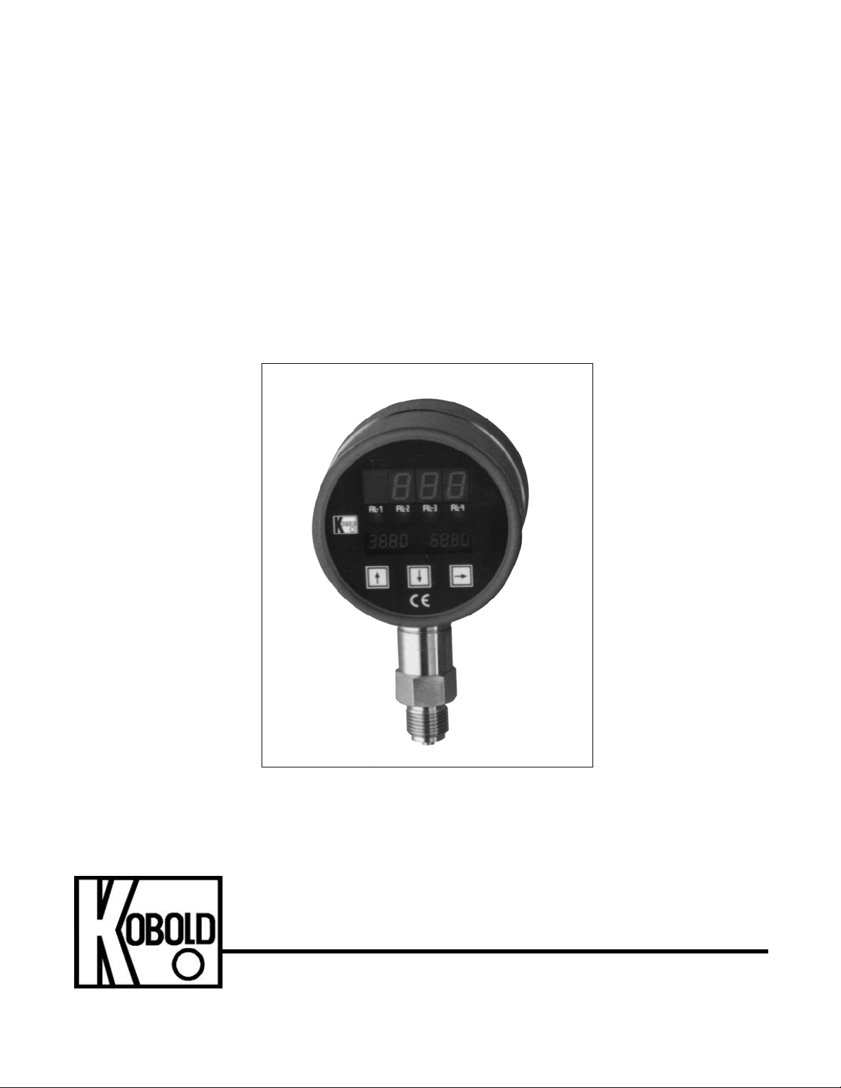
KOBOLD DSF26 Digital Pressure Gauge
User Instructions
KOBOLD Instruments Inc. 1801 Parkway View Drive Pittsburgh PA 15205
Phone (412) 788-2830 • Fax (412)-788-4890 • www.koboldusa.com
Manual-DSF26_12-13
Page 2

Page 3

DSF26
Table Of Contents
KOBOLD DSF26 DIGITAL PRESSURE GAUGE
1.0 General . . . .. . . . . . . . . . . . . . . . .. . . . . . . . . . . .. . . . . . . . . . . . . . . . . . . . . . 1
2.0 Specifications . . . . . . . . . . . . . . . .. . . . . . . . . . . .. . . . . . . . . . . . . . . . . . . . . . 2
3.0 Installation Instructions . . . . . . . . .. . . . . . . . . . . .. . . . . . . . . . . . . . . . . . . . . . 5
4.0 Operation . . .. . . . . . . . . . . . . . . . .. . . . . . . . . . . .. . . . . . . . . . . . . . . . . . . . . . 6
4.1 Turning the Unit On . . . . . .. . . . . . . . . . . .. . . . . . . . . . . . . . . . . . . . . . 6
4.2 Flow Measurement . . . . . .. . . . . . . . . . . .. . . . . . . . . . . . . . . . . . . . . . 6
5.0 Arrival of Damaged Equipment . .. . . . . . . . . . . .. . . . . . . . . . . . . . . . . . . . . . 6
6.0 Maintenance .. . . . . . . . . . . . . . . . .. . . . . . . . . . . .. . . . . . . . . . . . . . . . . . . . . . 6
7.0 Need Help With Your DSF26?. . . .. . . . . . . . . . . .. . . . . . . . . . . . . . . . . . . . . . 6
List of Diagrams
Diagram 2.4: Sensor Dimensions . . . . . . . . . . . . . . . . . . . . . . . . . . . . . . 4
Diagram 3.1: Wiring . . . . . . . . . .. . . . . . . . . . . .. . . . . . . . . . . . . . . . . . . . . . 5
List of Tables
Table 2.1: Material Combinations and Maximum Limits . . . . . . . . . . . . . . . . . . . 2
Table 2.2: Electrical Data. . . . . . . . . .. . . . . . . . . . . .. . . . . . . . . . . . . . . . . . . . . . 3
Table 2.3: Flow Ranges and Fitting Sizes . . . . . . . .. . . . . . . . . . . . . . . . . . . . . . 3
FM Rev. 12/03/13
Page 4

Page 5

DSF26
KOBOLD DSF26 DIGITAL PRESSURE GAUGE
User Instructions
CAUTION: For safety reasons, please read the cautionary information located at
the end of the manual, before attempting installation.
1.0 General
The DSF26 employs a piezo-resistive strain gauge element whose resistance varies in
proportion to an applied force (pressure). This variable resistance signal is conditioned to
provide an LED display and analog output. Optionally this meter can be provided with up
to 4 switches whose switch points and hysteresis are programmable.
2.0 Specifications
Table 2.1: General Specifications
Ranges: -14.7 to 5800 PSIG (see table 2.1 for
model numbers)
Over Pressure Protection:
To 3000 PSIG: 2X range Max.
Above 3000 PSIG: 1.5X range Max.
Sensor Type: Piezoresistive
Accuracy: ±0.5% of full scale ± 1 digit
Linearity: ±0.2% of full scale
Repeatability: ±0.1% of full scale
Operating Temperature:
Medium: -5°F to 220°F
Ambient: -5°F to 140°F
Storage: -40°F to 160°F
Temperature Drift Coefficients
Zero: < 0.05% of full scale/°F
Span: < 0,05% of full scale/°F
Sensing Membrane Location: Internal
Optional: Flush
Materials of Construction:
Wetted Parts: 316 Ti-Stainless Steel, Sapphire
Housing: 304 Stainless Steel, Polyamide
FM Rev. 12/03/13
Page 6

DSF26 2
Table 2.2: Electrical Data
Power Supply: 15-30 VDC, 300 mA Max. steady state,
Analog Output:
Current: 0-20 mA or 4-20mA into 500 ohms Max.
Voltage: 0-10 VDC into 500 Ohms Min.
Zero Adjust: ±25% of full scale
Relays (Optional):
Type: SPDT
Setpoints: Field Adjustable
Hysteresis: Field Adjustable
Max. Voltage: 250 VAC, 220 VDC
Max. Current: 3 Amps
Max. Power: 50 VA, 60 Watts
Displays:
Pressure: 4 digit, 0.5”, Green LED
Switch Setpoints: 4 Digit Backlit LCD
1 Amp inrush
Electrical Connections: Via Terminal St rip
Operating Temperatures:
Medium: -5° to 220°F
Ambient: -5° to 140°F
Storage: -40° to 160°F
Environmental Protection: IP65 (equivalent to NEMA 4)
FM Rev. 12/03/13
Page 7

3DSF26
Table 2.3: Part Number Decoding
DSF26 Digital Pressure Gauge with Analog Output
Range = Pressure Range Abbreviation
V15 = -14.7 to 0 PSIG 210 = 100 PSIG 270 = 700 PSIG 350 = 50
050 = 5 PSIG 215 = 150 PSIG 275 = 750 PSIG 358 = 58
110 = 10 PSIG 220 = 200 PSIG 310 = 1000 PSIG
115 = 15 PSIG 230 = 300 PSIG 315 = 1500 PSIG
130 = 30 PSIG 250 = 500 PSIG 320 = 2000 PSIG
160 = 60 PSIG 260 = 600 PSIG 330 = 3000 PSIG
Sensing Membrane Location
1 = Internal Membrane
1 = 1/4” NPT
2 = 1/2” NPT
3 = 3/4” NPT
4 = 4-20 mA Output
0 = 0-20 mA Output
1 = 0-10 VDC Output
G = 2 SPDT Limit Switches
H = 4 SPDT Limit Switches
Available Measuring Ranges
Fittings
Analog Output
Switches
-115
1 24
G
Sample DSF26 Specification
FM Rev. 12/03/13
Page 8
DSF26 4
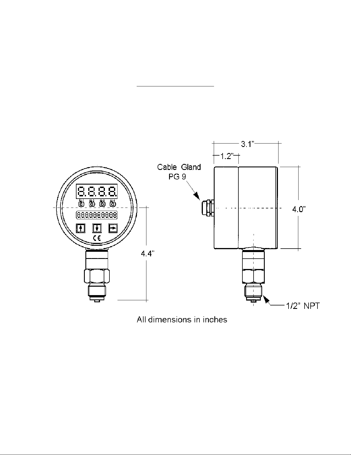
Diagram 2.4: Dimensions
FM Rev. 12/03/13
Page 9

5DSF26
3.0 Installation Instructions
CAUTION: For safety reasons, please read the cautionary information located at
the end of the manual, before attempting installation.
The following instructions and recommendations must be adhered to in order to ensure
proper pressure gauge installation:
1. When installed in horizontal piping runs, the gauge should be installed in the
upper hemisphere of the pipe, at the 12 O’clock position or within ±45° of the 12
O’clock position. This will ensure that sediments which may build up at the bottom of
the pipe will not clog the pressure sensing port (see Diagram 3.1).
Diagram 3.1: Pressure Gauge Installation
2. Install the gauge into a properly sized female port. Use of a thread sealant such
as PTFE tape is recommended to ensure a leak-tight seal.
3. When tightening the gauge into the piping system use a properly sized wrench on
the hex just above the threaded portion of the fitting. Do not use the case of the
gauge to apply torque or make or break the pressure connection.
FM Rev. 12/03/13
Page 10

DSF26 6
4.0 Electrical Connections
1. The DSF26 requires a 15-30 VDC power supply with at least 300 mA steady state
current capability. The unit has an inrush current of up to 1 Amp during the initial
startup transient. It is therefore necessary to ensure that the power supply used with
the DSF26 has a transient short-time current capability of at least 1 Amp.
2. The analog output signal wiring (if used) is made using either a 3-wire or 4-wire
connection as specified by the following wiring diagram:
CAUTION: THE DSF26 IS NOT A LOOP POWERED (2-WIRE) DEVICE.
DO NOT ATTEMPT TO USE A 2-WIRE CONNECTION AS THE
INTERNAL ELECTRONICS WILL BE DAMAGED IMMEDIATELY!!!
Diagram 4.1: Wiring
Note 1: Relays shown are optional
Note 2: Terminal blocks may be unplugged for wiring ease
Diagram 4.2: Power and Analog Output Connections
Terminal 10: DC Power (+)
Terminal 9: DC Power (-)
Terminal 8: Analog Output (+)
Terminal 7: Analog Output (-)
Terminals 1-6:Factory programming use only
FM Rev. 12/03/13
Page 11
5.0 Operation
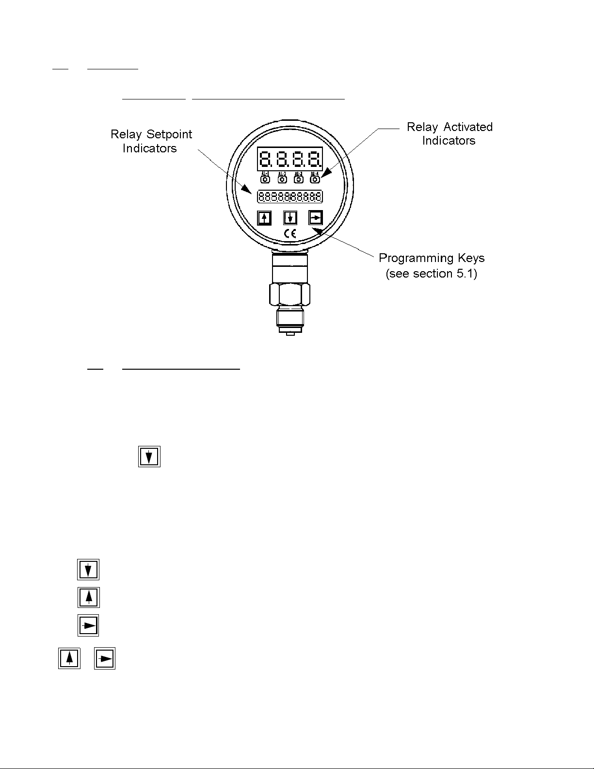
Diagram 5.1 DSF26 Displays and Controls
7DSF26
5.1 Programming, General
Programming is required in order to set the relay parameters and auto-zero the display if
needed. The programming menu items are displayed on the LCD display below the main
pressure display. The arrow keys on the front of the DSF26 are used to perform the
programming as follows:
Depressing the will place the DSF26 in the programming mode. EO - EbEnE will
be displayed on the LCD display. There are 4 branches in the programming mode (see
Diagram 5.2). Branch 1 sets Relay 1 parameters (setpoint, hysteresis etc.); Branch 2
sets the Relay 2 parameters; Branch three is used for auto- zeroing the display and
branch four is used only by the factory for initial setup. Menu items in branch 4 are locked
and cannot be altered by the user.
Programming key functions when in the programming mode (refer to Diagram 5.2)
Move to the next menu item
Move to the previous menu item
Move to the next branch. (only when at the first menu item in a branch)
Go back to the operating mode
FM Rev. 12/03/13
Page 12

DSF26 8
5.1 Programming, General (cont.)
When the numerical value of a menu item needs to be changed (e.g. changing relay
setpoint value) pressing the key will release the previous value to allow changing it.
the far right digit will be flashing to signify that the setting has been released to be
changed. Use or to change the value of that digit. Use to toggle to the next
digit. When the proper value is set, press & to enter the new value.
5.2 Programming Code Descriptions
The following is a listing of each programming code for the DSF26 along with a
description of its function. Diagram 5.2 shows a flow chart of the programming process:
E0 - EbEne Programming mode enabled. Pressing will toggle through each of
the 4 programming branches (see Diagram 5.2).
E0 - rELAiS1 Branch 1 for setting Relay 1 parameters. Use to move to the next
programming branch. Use to move down through the Relay 1
branch and set the Relay 1 parameters of setpoint, hysteresis, and
delay time.
SPt1 XXXX Relay 1 activation setpoint. To adjust the setpoint value, press the
key to release the previous setpoint value. the far right digit will be
flashing to signify that the setting has been released to be changed.
Use or to change the value of the flashing digit. Use to
toggle to the next digit. When the setpoint value is set, press &
to enter the new value.
HYS1 XXXX Relay 1 hysteresis. Hysteresis is defined in this as the temperature
setpoint where the relay de-activates. It is designed to allow for a
temperature “deadband” between the relay activation and de-activation.
To adjust the setpoint value, press the key to release the previous
setpoint value. the far right digit will be flashing to signify that the setting
FM Rev. 12/03/13
has been released to be changed. Use or to change the value
of the flashing digit. Use to toggle to the next digit. When the
setpoint value is set, press & to enter the new value.
Page 13

9DSF26
6.0 Maintenance
The DSF26 is an electronic device with no wear parts other than the relay contacts which
if properly connected will last for several hundred thousand cycles. The only
maintenance required on this device may be an occasional cleaning of the sensing port if
a coating or dirty process media exists. A possible indication of a dirty sensing port
would be a sluggish response to changes in process pressure.
Do NOT tamper with the electronics as this voids your warranty.
7.0 Need help with your DSF26?
Call one of our friendly engineers at 412-788-2830.
FM Rev. 12/03/13
Page 14

DSF26 10
Caution
PLEASE READ THE FOLLOWING GENERAL FLOW METER / MONITOR
WARNINGS BEFORE ATTEMPTING INSTALLATION OF YOUR NEW
DEVICE. FAILURE TO HEED THE INFORMATION HEREIN MAY
RESULT IN EQUIPMENT FAILURE AND POSSIBLE SUBSEQUENT
PERSONAL INJURY.
FM Rev. 12/03/13
Page 15

11 DSF26
• User's Responsibility for Safety: KOBOLD manufactures a wide range of
process sensors and technologies. While each of these technologies are
designed to operate in a wide variety of applications, it is the user's
responsibility to select a technology that is appropriate for the application,
to install it properly , to perform test s of the installed system, and to maintain
all components. The failure to do so could result in property damage or
serious injury.
• Inspect instrument for damage upon arrival: Cracked, fractured, bent or
otherwise damaged instruments must not be put into use, since the device
is weakened to an unknown extent. Refer to Section 5.0, Arrival of
Damaged Equipment, for additional information.
• Media and Chemical Compatibility: The maximum tolerances of the
device have been determined using water. If using other media, especially
corrosive media, it is critically important that the user determine chemical
compatibility with our instruments. KOBOLD Instruments Inc. cannot
accept responsibility for failure and consequences resulting from use of
media other than water.
• Material Compatibility: Make sure that the model which you have
selected is chemically compatible with the application liquids. While the
meter is liquid and spray resistant when installed properly, it is not
designed to be immersed.
• Proper Installation in Flow System: Install the device in a fully supported
position within your flow system. This avoids excessive stresses which may
damage the instrument. In particular:
a.) Ensure that the plumbing leading to and from the instrument is fully
supported and that the instrument does not perform the physical function of
a joint.
b.) When calculating stress on the device caused by plumbing, the weight
of the medium in the pipes must be considered as well.
c.) Misaligned runs of rigid piping can cause large stresses when
connected to the instrument. Do not connect in such a fashion.
d.) When connecting fittings, hold the instrument fittings rigid with a
correctly sized wrench. Do not install by twisting the instrument into the
pipe fittings.
e.) Do NOT install by holding the device housing to provide counter-torque
to the pipe fitting.
f.) Use an appropriate amount of PTFE tape on male threads of fitting. This
reduces the twisting stresses produced by tightening the fittings into each
other.
g.) Do not use pliers or wrenches on the housing, as this may damage it.
FM Rev. 12/03/13
Page 16

DSF26 12
h.) Do not overtighten, as this may fracture the fittings.
• While Operating the Flow System: During operation, there are a number
of situations to avoid:
a.) The sudden cessation of fluid flow causes what is typically referred to
as "water hammer". Most people are familiar with this phenomenon from
their home experience - it is the cause behind the loud clank of water pipes
which occurs when faucets are turned off too suddenly. The cause behind
this "water hammer" is quite easy to visualize. Water is fairly massive. The
amount of water in long runs of pipe is quite substantial. When the faucets
are turned off suddenly, especially from a full on condition, the water has
considerable momentum and does not want to stop flowing. The situation
is similar to stopping a car by running into a wall, rather than by applying
brakes. Both are sudden rather than gradual. The damage to the wall can
be substantial (not to mention the car).
b.) The "water hammer" causes surges in fluid pressure which could cause
the measurement instrument's pressure limit to be exceeded, resulting in
failure and possible personal injury.
c.) Fluid surges, as well as the water hammer, can be particularly
damaging to empty flowmeters since there is no back pressure in the
device. The damage is caused, once again, by momentary excess
pressure. To avoid these surges, fluid lines should remain full (if possible)
and water flow should be introduced to the device slowly.
d.) If the instrument is isolated with inlet and outlet valves, the flowmeter
must be completely drained when said valves are both closed. Failure to
do so could result in damage to the device caused by thermal expansion of
fluid.
e.) Freezing of water in the instrument must be avoided since the resultant
expansion will damage the flowmeter and make it unsafe for use.
• Wiring and Electrical: Section 2.0, Specifications and Section 3.0,
Installation Instructions, provide the voltage and current limitations and the
wiring for the various sensor types. The sensor electrical ratings should
never be exceeded. Electrical wiring of the sensor should be performed in
accordance with all applicable national, state and local codes.
• Temperature and Pressure: Section 2.0, Specifications, provides the
temperature and pressure limits for each model. Operation outside these
limitations will cause damage to the unit and can potentially cause personal
injury. Fluid should never be allowed to freeze inside the sensor.
• Make a Fail-safe System: Design a fail-safe system that accommodates
the possibility of switch or power failure. In critical applications, KOBOLD
recommends the use of redundant backup systems and alarms in addition
to the primary system.
FM Rev. 12/03/13
 Loading...