

Page 1
Operating Instructions
for
Piston Flow Meters
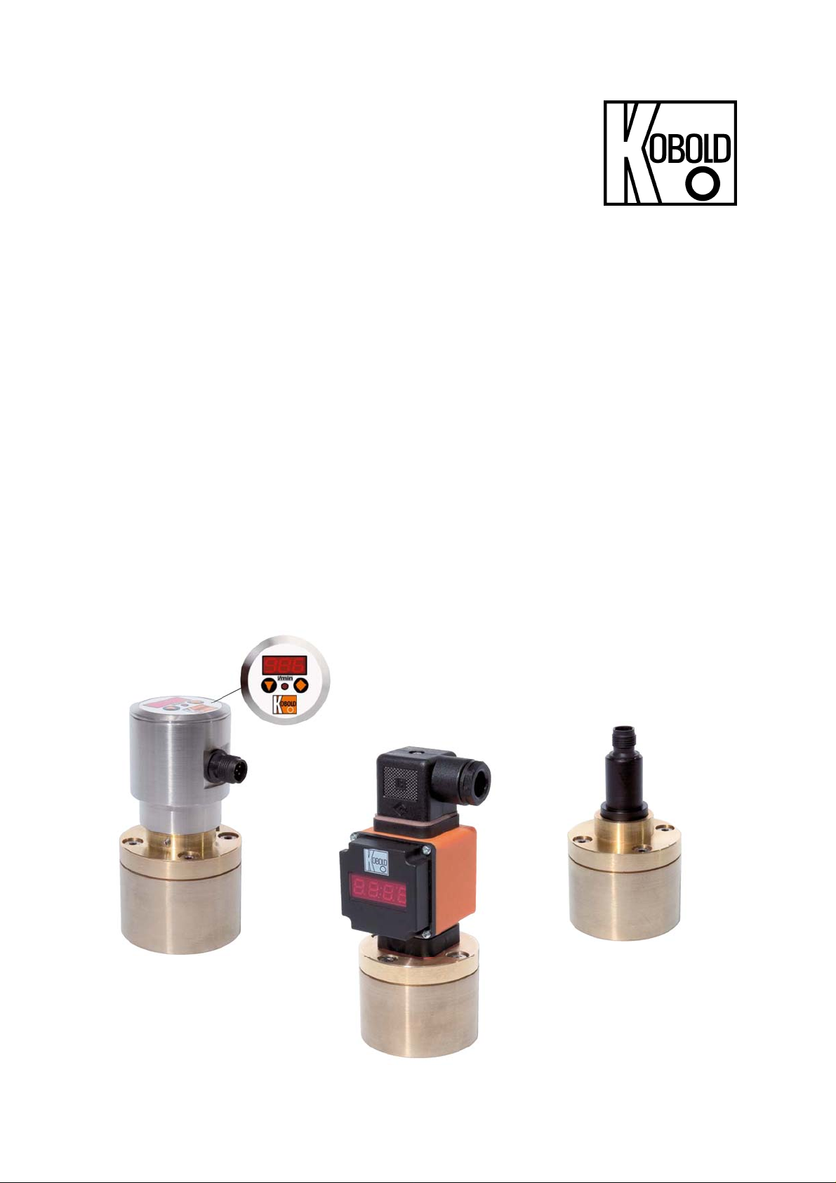
Model: DRZ
Page 2

DRZ
1. Contents
1. Contents ........................................................................................................ 2
2. Note .............................................................................................................. 3
3. Instrument Inspection .................................................................................... 3
4. Regulation Use .............................................................................................. 3
5. Operating Principle ........................................................................................ 4
6. Mechanical Connection ................................................................................. 5
7. Electrical Connection .................................................................................... 5
7.1 General ................................................................................................ 5
8. Technical Information .................................................................................... 7
9. Order Codes ................................................................................................. 8
10.Dimensions ................................................................................................... 9
11.Pressure Loss Diagram ............................................................................... 12
12.EU Declaration of Conformance .................................................................. 13
Manufactured and sold by:
Kobold Messring GmbH
Nordring 22-24
D-65719 Hofheim
Tel.: +49(0)6192-2990
Fax: +49(0)6192-23398
E-Mail: info.de@kobold.com
Internet: www.kobold.com
page 2 DRZ K03/0418
Page 3

DRZ
2. Note
Please read these operating instructions before unpacking and putting the unit
into operation. Follow the instructions precisely as described herein.
The devices are only to be used, maintained and serviced by persons familiar
with these operating instructions and in accordance with local regulations
applying to Health & Safety and prevention of accidents.
When used in machines, the measuring unit should be used only when the
machines fulfil the EC-machine guidelines.
as per PED 2014/68/EU
In acc. with Article 4, Paragraph (3), "Sound Engineering Practice", of the
PED 2014/68/EU no CE mark.
Diagram 8, Pipe, Group 1 dangerous fluids
3. Instrument Inspection
All Instruments are inspected before shipping and sent out in perfect condition.
Should damage to a device be visible, we recommend a thorough inspection of
the delivery packaging. In case of damage, please inform your parcel service /
forwarding agent immediately, since they are responsible for damages during
transit.
Scope of delivery:
The standard delivery includes:
Piston Flow Meters model: DRZ
Operating Instructions
4. Regulation Use
Any use of the Piston Flow Meters, model: DRZ, which exceeds the
manufacturer’s specification, may invalidate its warranty. Therefore, any resulting
damage is not the responsibility of the manufacturer. The user assumes all risk
for such usage.
DRZ K03/0418 page 3
Page 4
DRZ
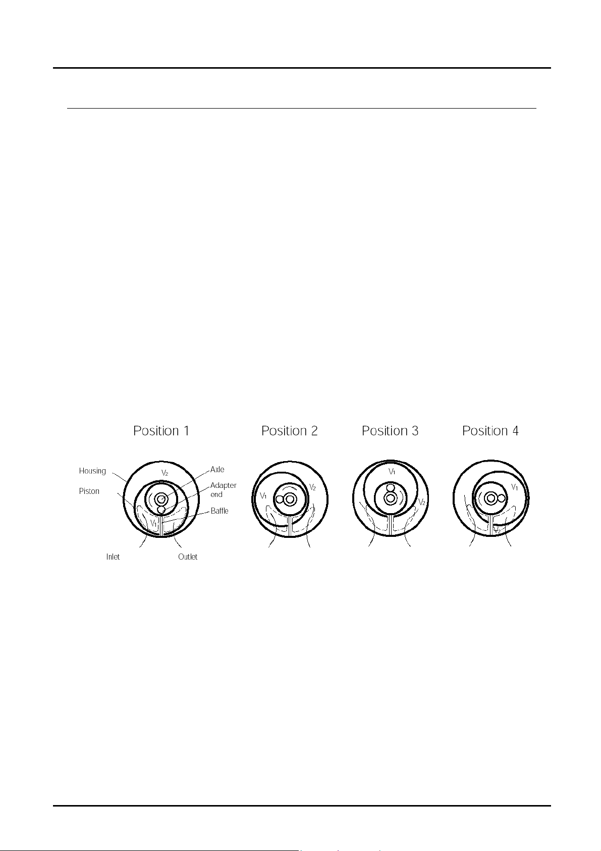
5. Operating Principle
KOBOLD Piston Flow Meters are direct volume counters, also called
displacement counter (positive displacement meter).
Its function is based on continuous limitation of a definite part-volume of the flow
in a measuring cell through continuous filling and emptying of this measuring cell.
The measuring cell consists of the measuring chamber and the moving part, the
piston.
The piston is driven by the pressure difference between inlet and outlet of the
measured media. The counter is a pure mechanical instrument. The revolution is
carried forward via a magnet and a magnet field sensor. In cross section the uformed piston is guided with its piston and guiding-adapter in a ring chamber at
the bottom and top of the measuring-body and with its slot at the baffle. The inlet
and outlet openings are located on both sides of the chamber’s wall. They are
constantly sealed by the piston and the baffle. The incoming measured media fills
up the sickle shaped spaces, it wants to increase these spaces and therefore
turns the piston. Until one after the other the volumes V1 and V2 are reached.
While moving ahead, these filled spaces are connected with the outlet and are
emptied. Since both sickle shaped spaces - the inner and the outer - are
displaced to one another, the piston movement will not have a dead centre. The
piston moves continuously depending to the measured flow.
One complete turn of the piston adapter end is equal to the flow of the measuring
chamber content (V1+V2). With the help of a located magnet and a Hall-type
sensor, it is possible to create a digital signal, which can be evaluated.
page 4 DRZ K03/0418
Page 5

DRZ
6. Mechanical Connection
Before installation:
Remove all packing materials, transport retainers and ensure that no such
materials remain in the device.
Make sure that the maximum operating pressure and temperature of the device
are not exceeded.
Please ascertain, that the pipe system is free of any welding bead, ferrite
particles or other pollution.
Make sure that the application flow amount corresponds with the flow range of
the instruments.
Installation
The mounting position of the piston is free of choice. The flow direction must
be in the direction as indicated by the arrow.
In- and outlet flow sections are not necessary.
The sealing of the connection threads is done with sealing tape or something
similar.
During installation, please pay attention that the DRZ-instrument is not
exposed to mechanical stress or tension. We recommend to mechanically
fastening the connection pipes approximately 50 mm away from the
connection thread.
If possible, after completing the mechanical installation, check the thread
connection between the device and the piping for leakage immediately.
7. Electrical Connection
7.1 General
Make sure that the supply wires are de-energised.
Connect the power supply and the evaluation of the output signal to the pins of
the plug described as follows.
Warning! Incorrect wiring of the connections in the coupling plug
can lead to the electronics being destroyed. Make sure that the
voltage values of your installation correspond with the voltage
values of the measuring instrument.
DRZ K03/0418 page 5
Page 6

DRZ
DRZ-..F3..; DRZ-..L3..
DRZ-..0000
DRZ-..C3..
page 6 DRZ K03/0418
Page 7

DRZ
8. Technical Information
Measuring range: 6-420 L/h
Max. flow rate: 600 L/h
Measuring accuracy: ± 1.0% of reading
± 2.5% of reading
Repeatability: ± 0.2%
Standard viscosity range: 5-100 mm2/s
Process temperature: max. 80 °C
Ambient temperature: -10 to +60 °C
Max. pressure: 40 bar
Max. pressure loss: 1.5 bar
Connection: female thread G 1/8; G 1/4;
1/8 NPT; 1/4 NPT
Mounting position: independent
Recom. filter fineness: 100 µm
Protection type: IP 65
Weight: approx. 0.7 kg
(DRZ-..F.., DRZ-..L..)
approx. 1.0 kg (DRZ-..C..)
Materials:
Housing: brass
Piston: titanium
Magnet holder: POM
Magnet: permanent magnet
O-ring/Seal: FPM
Electronics
OEM frequency output (...0000) (without CE)
Power supply: 5-24 VDC
Supply current: 10 mA
Pulse output: NPN, open collector,
max. 15 mA
Impulse rate: 405 pulses/litre
Electr. connection: plug connector DIN 43650
Option: plug-on display AUF-4000
with 4 -20 mA output
Frequency output (...F300)
Power supply: 12-28 VDC
Supply current: 10 mA
Pulse output: PNP, open collector,
max. 25 mA
Impulse rate: 432 pulses/litre
Electr. connection: plug connector M12x1
DRZ K03/0418 page 7
Page 8

DRZ
Frequency output with frequency divider (...F3X0)
Power supply: 24 VDC ± 20%
Supply current: 15 mA
Pulse output: PNP, open collector,
max. 25 mA
Electr. connection: plug connector M12x1
Division factor: 1:2, 1:4 or customer request
Analogue output (...L303; ...L343)
Power supply: 24 V
DC ±20%
Output: 4-20 mA, 0-20 mA, 3-wire
Max. load: 500 .
Electr. connection: plug connector M12x1
Compact electronics (..C3..)
Display: 3-segment LED
Analogue output: (0)4...20 mA adjustable, max. 500
Switching output: 1 (2) semiconductor PNP
or NPN, factory setting
Contact function: N/C or N/O programmable
Setting: via 2 buttons
Power supply: 24 V
DC ±20%,
3-wire technology
Electr. connection: plug connector M12x1
9. Order Codes
Example: DRZ-1110 G1 F300
Version Model Connection Evaluating electronics
Brass housing
6 - 420 L/h oil
DRZ-1110
G1 = G 1/8 IG
G2 = G 1/4 IG
N1 = 1/8 NPT
N2 = 1/4 NPT
OEM frequency output, no CE
0000 = DIN plug connector 43650, NPN
Frequency output
F300 = plug connector M12x1, PNP
F320 = plug connector M12x1, PNP, divider 1:2
F340 = plug connector M12x1, PNP, divider 1:4
F390 = plug connector M12x1, PNP, divider adjustable
Analogue output
L303 = plug connector M12x1, 0 - 20 mA, 3-wire
L343 = plug connector M12x1, 4 - 20 mA, 3-wire
Compact electronics
C30M = LED display, 2x NPN switch. output, plug con. M12x1
C30R = LED display, 2x PNP switch. output, plug con. M12x1
C34N = LED display, 4 - 20 mA, 1x NPN switching output,
plug connector M12x1
C34P = LED display, 4 - 20 mA, 1x PNP switching output,
plug connector M12x1
1)
Please specify flow direction in wiring.
1)
page 8 DRZ K03/0418
Page 9

DRZ
Plug-on display
for model DRZ...0000 (OEM version, NPN- and DIN connector)
Description Order No.
4-digit LED,
Plug connector DIN 43 650
Input: pulses of DRZ
Output: 4 - 20 mA, 3-wire
Load: max. 250
Accessories
Round plug
Model Description
ZUB-KAB-12D500 Round plug M12 x 1 socket with screw clamps, 5 pins
ZUB-KAB-12K002 Round plug M12 x 1 socket with 2 m cable, 4 pins
ZUB-KAB-12K005 Round plug M12 x 1 socket with 5 m cable, 4 pins
ZUB-KAB-12Q000 Round plug M12 x 1 socket with Quick-on, 4 pins
AUF-4000
10. Dimensions
3 x M 5-10 deep
DRZ K03/0418 page 9
Page 10

DRZ
page 10 DRZ K03/0418
Page 11

DRZ
DRZ K03/0418 page 11
Page 12

DRZ
11. Pressure Loss Diagram
page 12 DRZ K03/0418
Page 13

DRZ
12. EU Declaration of Conformance
We, KOBOLD Messring GmbH, Hofheim-Ts, Germany, declare under our sole
responsibility that the product:
Piston Flow Meters Model: DRZ
to which this declaration relates is in conformity with the standards noted below:
EN 61000-6-3:2011
Electromagnetic compatibility (EMC) - Part 6-3: Generic standards - Emission
standard for residential, commercial and light-industrial environments
61000-6-2:2006
Electromagnetic compatibility (EMC) - Part 6-2: Generic standards - Immunity for
industrial environments
EN 61010-1:2010
Safety requirements for electrical equipment for measurement, control and
laboratory use - Part 1: General requirements
EN 60529:2014
Degrees of protection provided by enclosures
EN 50581:2012
Technical documentation for the assessment of electrical and electronic products
with respect to the restriction of hazardous substances
Also the following EC guidelines are fulfilled:
2014/30/EU EMC Directive
2014/35/EU Low Voltage Directive
2011/65/EU RoHS (category 9)
Hofheim, 11. Jan. 2018
H. Peters M. Wenzel
General Manager Proxy Holder
DRZ K03/0418 page 13
 Loading...