

Kobold DRG Series, DRG-F Series, DRZ-**Z Series, DRG-**L442, DRG***L3 Series Operating Instructions Manual
...Page 1

Operating Instruction
for
Rotating Vane Flow Meter
Model: DRG-...
Page 2

DRG
Page 2 DRG K02/0316
1. Contents
1.
Contents ........................................................................................................ 2
2. Note .............................................................................................................. 3
3. Regulation Use .............................................................................................. 3
4. Operating Principle ........................................................................................ 3
5. Instrument Inspection .................................................................................... 4
6. Mechanical Connection ................................................................................. 4
7. Electrical Connection .................................................................................... 5
8. Commissioning – Evaluation Electronics ...................................................... 8
9. Technical Information .................................................................................... 8
10.Order Details ............................................................................................... 10
11.Maintenance ............................................................................................... 11
12.Dimensions ................................................................................................. 11
13.EU Declaration of Conformance .................................................................. 14
Manufactured and sold by:
Kobold Messring GmbH
Nordring 22-24
D-65719 Hofheim
Tel.: +49(0)6192-2990
Fax: +49(0)6192-23398
E-Mail: info.de@kobold.com
Internet: www.kobold.com
Page 3

DRG
DRG K02/0316 Page 3
2. Note
Please read these operating instructions before unpacking and putting the unit
into operation. Follow the instructions precisely as described herein.
The devices are only to be used, maintained and serviced by persons familiar
with these operating instructions and in accordance with local regulations
applying to Health & Safety and prevention of accidents.
When used in machines, the measuring unit should be used only when the
machines fulfil the EG-machine guidelines.
PED 2014/68/EU
In acc. with Article 4 Paragraph (3), "Sound Engineering Practice", of the
PED 2014/68/EU no CE mark.
Table 8, Pipe, Group 1 dangerous fluids
3. Regulation Use
The Model DRG-..., rotating vane flow meter is to be installed only in applications
that are within the specified operating limits. An use which exceeds the
specifications is prohibited. Any damages resulting therefrom are not the
responsibility of the manufacturer. The user assumes all risk for such usage. The
application specifications include the installation, start-up and service
requirements specified by the manufacturer.
4. Operating Principle
KOBOLD rotating vane flow meters series DRG are used for measuring and
monitoring low viscosity liquids. Series DRG flow meters are working according
the well known rotating vane principle. A magnet fitted in the vane and
hermetically sealed from the medium transfers the rotary motion of the vane to a
Hall-effect sensor mounted in the housing. The sensor converts the rotary motion
which is proportional to the flow to a frequency signal. The frequency is therefore
proportional to flowrate. A series-connected electronics unit converts the signal to
an analogue output, limit contacts or display.
Page 4

DRG
Page 4 DRG K02/0316
5. Instrument Inspection
These devices are checked before dispatch and sent away in perfect condition.
Should the damage to a device be visible, we recommend a thorough inspection
of the delivery packing. In case of damage, please inform your parcel service/
forwarding agent immediately, since they are responsible for damages during
transit.
Scope of delivery:
Rotating Vane Flow Meter model: DRG
Operating Instructions
6. Mechanical Connection
6.1. Operational conditions check up:
Max. flowrate
Max. operational pressure
Max. operational temperature
Attention! In case, specified range is over-violated, bearings may get
damaged and considerable measurement errors may result.
6.2. Installation
It must be ensured that the instrument housing is continuously filled with the
flow medium, especially for flows from top to bottom. No straight lengths are
necessary at inlet and outlet connections.
Flow in the direction of arrow pointer (position independent), front side of the
unit must stand in a vertical plane.
Pressure and tensile loading should be avoided.
Inlet and outlet (piping) should be braced at a distance of 50 mm from the
connection location.
Sealing of connections should be checked.
Page 5
DRG
DRG K02/0316 Page 5
7. Electrical Connection
7.1. General
Attention! Please ensure that the voltage levels of your system are
in agreement with that of the flow meter.
Make sure that the electric supply lines are de-energized.
Connect the power supply and output signal on the plug-pins as shown below.
We recommend a cross-sectional area of 0.25 mm² of power supply cable.
Attention! A wrong plug-connection can lead to destruction of
unit’s electronics.
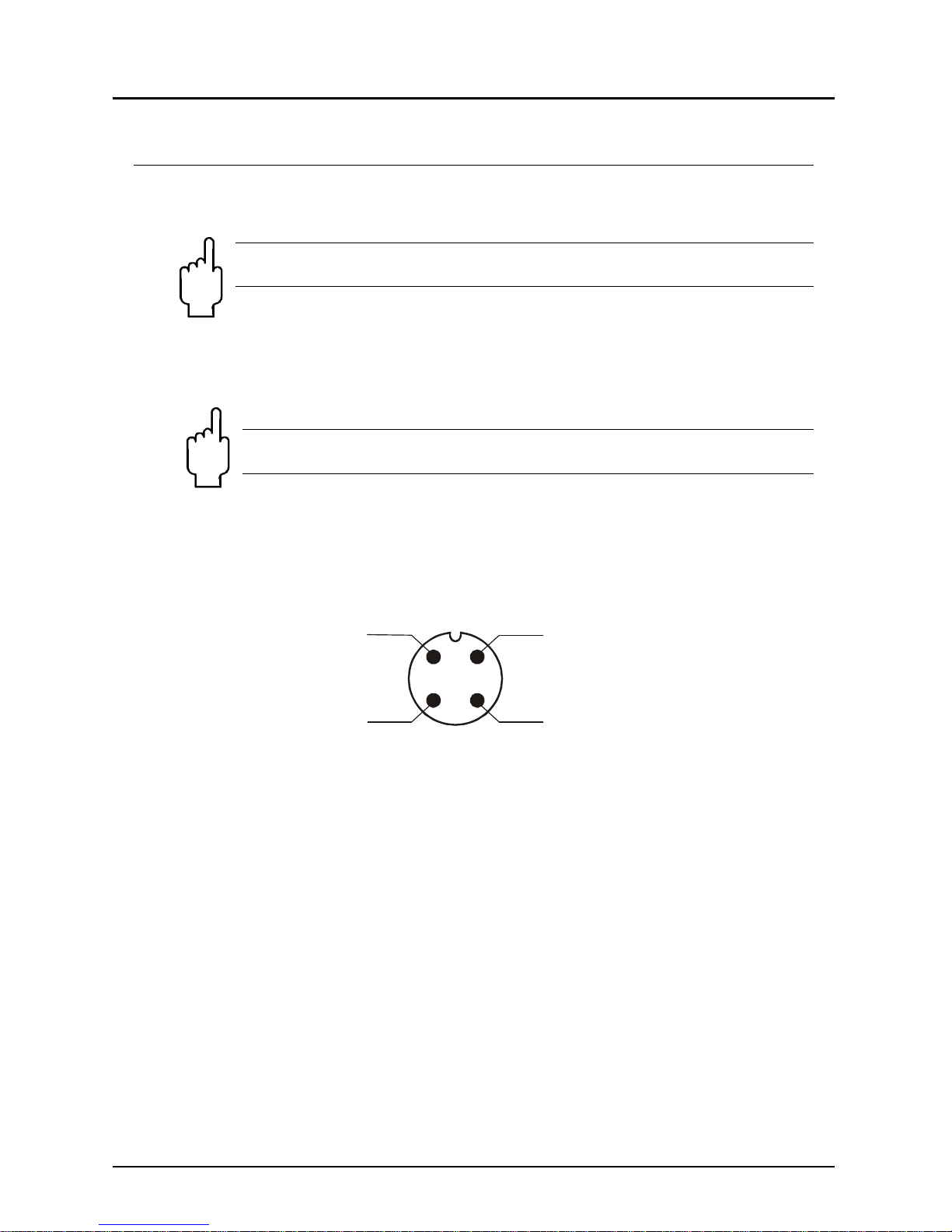
7.2. Evaluation electronics: Frequency output (..F300; ..F320,
..F340)
1
2
3
4
+Vs
Signal
Out
n.c.
GND
Page 6

DRG
Page 6 DRG K02/0316
7.3. Evaluation electronics:
Analogue output (..L303, ..L342, ..L343, ..L442)
3-wire (..L303, ..L343)
1
2
3
4
+Vs
Signal
Out
n.c.
GND
+Vs
GND
2-wire (..L342)
1
2
3
4
S+
S-
n.c.
n.c.
+Vs
GND
2-wire, DIN-plug (..L442)
+Vs
GND
1
2
3
S+
S-
PE
n.c.
Page 7

DRG
DRG K02/0316 Page 7
7.4. Compact electronics:
(..C30R, ..C30M, ..C34P, ..C34N)
Please see
Instruction Manual-Supplement
for Compact Electronics
7.5. Evaluation electronics: Pointer display (..Z300, ..Z340)
Attention! If the current output is not needed, PIN 4 (Signal Out) must
be connected permanently with Ground (GND) (Short Circuit Link).
mA
+Vs
GND
Power
1
2
3
4
+Vs
Signal
Out
n.c.
GND
Plug M12
Page 8

DRG
Page 8 DRG K02/0316
8. Commissioning – Evaluation Electronics
8.1. General
The measuring units are pre-adjusted and ready for use after electrical
connection.
8.2. Adjustment – Evaluation Electronics
Please see
Instruction Manual-Supplement
for Compact Electronics with frequency output
9. T echnical Information
9.1. Sensor data
Material combinations: see order details
Max. operating pressure: see order details
Max. temperature: see order details
Measuring accuracy: ±3% f. s.
Electrical connection: plug connector DIN 43 650,
plug connector M12x1
Pressure loss: max. 1 bar at max. range value
Protection: IP 65
Unit parts Ordering
code:
1
Ordering
code:
2
Ordering
code:
4
Ordering
code:
5
Ordering
code:
8
Ordering
code:
9
Housing
Brass
casting
Brass
casting
1.3955 1.3955 PP PP
Housing cover
PSU Brass
casting
PSU 1.4404 PP PSU
Sealing
NBR NBR FPM FPM NBR NBR
Vane
PTFE PTFE PTFE PTFE PTFE PTFE
Axle
Ceramic Ceramic Ceramic Ceramic Ceramic Ceramic
Bearings
PTFE PTFE PTFE PTFE PTFE PTFE
Max. Pressure
16 bar 40 bar 16 bar 40 bar 7 bar 7 bar
Max. Temp.
80°C 80°C 80°C 80°C 80°C 80°C
Sensor Weight
580 g 580 g 480 g 480 g 120 g 120 g
Page 9

DRG
DRG K02/0316 Page 9
9.2. Evaluation electronics
Frequency output (...F300)
Supply voltage: 12 - 28 VDC
Current intake: 10 mA
Pulse output: PNP, open collector, max. 25 mA
Electrical connection: Plug M12x1
Frequency output with frequency divider
Supply voltage: 24 VDC ±20%
Current intake: 15 mA
Pulse output: PNP, Open Collector, max. 25 mA
Electrical connection: Stecker M12x1
Dividing factor: 1...1/128, factory setting
Analogue output (option: on-plug display)
Supply voltage: 24 VDC ±20%
Output: 0-20 mA or 4-20 mA,
2- or 3-wire
Max. load: 500 Ohm
Electrical connection: Plug M12x1 or DIN 43 650
Option: plug-on display
(only with plug DIN 43 650
and 4-20 mA output), 2 conductor
Compact electronics
Display: 3-digit LED
Analogue output: (0)4 -20 mA adjustable, max. 500 Ω
Switching outputs: 1 (2) semiconductor PNP or NPN,
factory set
Contact operation: N/C / N/O contact frequency
programmable
Setting: with 2 buttons
Supply: 24 V
DC ±20%, 3-wire technology,
approx. 100 mA
Electrical connection: plug connector M12x1
Pointer display with analogue output
Housing: Aluminium
Display: Moving-coil instrument, 240° display
Suppkly voltage: 24 V
DC ±20%
Output: 0-20 mA or 4-20 mA
3-conductor
Max. load: 250 Ohm
Electr. connection: Plug M12x1
Page 10

DRG
Page 10 DRG K02/0316
10. Order Details
(example: DRG-1105 G1 F300)
Measuring range
Orifice
diameter
durch-
[mm]
Model
Connection
Evaluating electronics
L/min
water
approx.
frequency
(Hz)
at f.s.
Standard
fem. thread
Special
fem. thread
0,5-12 120 6
DRG-1X05... ..G1..=G 1/8 ..N1..=1/8 NPT
Frequency output
..F300= Frequency output, plug connector M12x1
..F320= Frequency divider 1:2, plug connector M12x1
..F340= Frequency divider 1:4, plug connector M12x1
..F390= Frequency divider 1...
1
/128, plug connector M12x1
Analogue output
..L303= 0-20 mA output, 3-wire, plug connector M12x1
..L342= 4-20 mA output, 2-wire, plug connector M12x1
..L343= 4-20 mA output, 3-wire, plug connector M12x1
..L442= 4-20 mA output, 2-wire, plug connector DIN 43 650
Compact electronics*
..C30R= LED display, 2x open coll., PNP, plug con. M12x1
..C30M= LED display, 2x open coll., NPN, plug con. M12x1
..C34P= LED display, 4-20 mA, 1x open coll., PNP,
plug connector M12x1
..C34N= LED display, 4-20 mA, 1x open coll., NPN,
plug connector M12x1
Pointer indication*
..Z300= 240° - pointer indication, 0-20 mA, plug con. M12x1
..Z340= 240° - pointer indication, 4-20 mA, plug con. M12x1
0,5-25 217 6
DRG-1X10... ..G2..=G ¼ ..N2..=1/4 NPT
1-30 217 8
DRG-1X15... ..G2..=G ¼ ..N2..=1/4 NPT
1-30 190 7
DRG-1X15... ..G4..=G ½ ..N4..=1/2 NPT
2-45 215 8
DRG-1X20...
..G4..=G ½
..G5..=G ¾
..G6..=G 1
..N4..=1/2 NPT
..N5..=3/4 NPT
..N6..=1 NPT
5-90 265 12
DRG-1X25...
..G4..=G ½
..G5..=G ¾
..G6..=G 1
..N4..=1/2 NPT
..N5..=3/4 NPT
..N6..=1 NPT
5-140 116 16
DRG-1X30... ..G5..=G ¾ ..N5..=3/4 NPT
10-140 180 16
DRG-1X35... ..G6..=G 1 ..N6..=1 NPT
* Please specify flow direction in writing
Plug-on display
For Model DRG... L342 (with 4-20 mA output and DIN plug connector)
Page 11

DRG
DRG K02/0316 Page 11
11. Maintenance
If the medium to be measured is not contaminated, the measuring unit is
maintenance-free. In order to avoid problems, we recommend installation of a
filter, such as magnet filter, model MFR.
Should cleaning of sensor be deemed necessary, the sensor may be opened and
inner parts may be accessed. Please be attentive during dismantling so that the
sensor and in particular, the vane is not damaged. During assembly the right
placement and the mounting direction of the vane should not be overlooked.
Electronic repairs may only be carried out by the manufacturer to prevent voiding
of warranty.
12. Dimensions
Model: DRG – F... (frequency output) DRG...L3...
(with analogue output)
O
B
O
L
D
E
4,5
ca.107
50
SWA
B
M12x1
60
G
C
G/NPTABCESW
1/8 80 16,5 63,0 72,5 24
1/4 80 16,5 63,0 72,5 24
1/2 80 16,5 63,0 72,5 24
3/4 100 25,0 69,5 90,0 38
1 100 25,0 69,5 90,0 38
Page 12

DRG
Page 12 DRG K02/0316
Model: DRG-..L442
(analogue output and option plug-on display)
OBOLD
A
E
4,5
12 117
50
SW
C
B
42
G
60
G/NPT A B C E SW
1/8 80 16,5 63,0 72,5 24
1/4 80 16,5 63,0 72,5 24
1/2 80 16,5 63,0 72,5 24
3/4 100 25,0 69,5 90,0 38
1 100 25,0 69,5 90,0 38
Model: DRG-..C.. (with Compact Electronics)
A
E
4,5
M12x1
SW
50
120,5
C
+2
B
44,5
60
G
GA B C ESW
1/8 80 16,5 63,0 72,5 24
1/4 80 16,5 63,0 72,5 24
1/2 80 16,5 63,0 72,5 24
3/4 100 25,0 69,5 90,0 38
1 100 25,0 69,5 90,0 38
Page 13

DRG
DRG K02/0316 Page 13
Model: DRG-..Z.. (with pointer display)
A
M12x1
E
133,5
99
50
SW
C
+2
B
4,5
79,7
65
60
G
G/NPT A B C E
1/8 80 16,5 63,0 72,5
1/4 80 16,5 63,0 72,5
1/2 80 16,5 63,0 72,5
3/4 100 25,0 69,5 90,0
1 100 25,0 69,5 90,0
Page 14

DRG
Page 14 DRG K02/0316
13. EU Declaration of Conformance
We, KOBOLD-Messring GmbH, Hofheim-Ts, Germany, declare under our sole
responsibility that the product:
Rotating Vane Flow Meter Model: DRG -...
to which this declaration relates is in conformity with the standards noted below:
EN 61000-6-4:2011
Electromagnetic compatibility (EMC) - Part 6-4: Generic standards - Emission
standard for industrial environments
EN 61000-6-2:2005
Electromagnetic compatibility (EMC) - Part 6-2: Generic standards - Immunity for
industrial environments
EN 61010-1:2010
Safety requirements for electrical equipment for measurement, control and
laboratory use - Part 1: General requirements
EN 60529:2014
Degrees of protection provided by enclosures (IP Code)
Also the following EU guidelines are fulfilled:
2014/35/EU Low Voltage Directive
2014/30/EU EMC Directive
2011/65/EU RoHS (category 9)
Hofheim, 27. Apr. 2016
H. Peters M. Wenzel
General Manager Proxy Holder
 Loading...