

Page 1
Operating Instruction
for
Turbine-wheel Flow Meter
Model: DRB-...
Page 2

DRB
Page 2 DRB K04/0318
1. Contents
1. Contents ........................................................................................................ 2
2. Note .............................................................................................................. 3
3. Instrument Inspection .................................................................................... 3
4. Regulation Use .............................................................................................. 3
5. Operating Principle ........................................................................................ 4
6. Mechanical Connection ................................................................................. 4
7. Electrical connection ..................................................................................... 7
8. Commissioning – Evaluation Electronics .................................................... 10
9. Maintenance ............................................................................................... 10
10.Technical Data ............................................................................................ 11
11.Order Details ............................................................................................... 14
12.Dimensions (mm) ........................................................................................ 15
13.EU Declaration of Conformance .................................................................. 18
Manufactured and sold by:
Kobold Messring GmbH
Nordring 22-24
D-65719 Hofheim
Tel.: +49(0)6192-2990
Fax: +49(0)6192-23398
E-Mail: info.de@kobold.com
Internet: www.kobold.com
Page 3

DRB
DRB K04/0318 Page 3
2. Note
Please read these operating instructions before unpacking and putting the unit
into operation. Follow the instructions precisely as described herein.
The devices are only to be used, maintained and serviced by persons familiar
with these operating instructions and with the prevailing regulation applying to
safety and the prevention of accidents.
When used in machines, the measuring unit should be used only then when the
machines fulfil the EC-machine guide lines.
PED 2014/68/EU
In acc. with Article 4 Paragraph (3), "Sound Engineering Practice", of the
PED 2014/68/EU no CE mark.
Table 8, Pipe, Group 2 dangerous fluids
3. Instrument Inspection
These devices are checked before shipping and sent out in perfect condition.
Should damage to a device be visible, we recommend a thorough inspection of
the delivery packing. In case of damage, please inform your parcel service/
forwarding agent immediately, since they are responsible for damages during
transit.
Scope of delivery:
Turbine-wheel Flow Meter, Model: DRB
Operating Instructions
4. Regulation Use
The “turbine-wheel flow meter, model DRB“, is to be installed only in specified
applications. Any usage which exceeds the specifications is considered to be nospecified, and would also invalidate the warranty. Any damages resulting
therefrom are not the responsibility of the manufacturer. The user assumes all
risk for such usage. The application specifications include the installation, start-up
and service requirements specified by the manufacturer.
Page 4

DRB
Page 4 DRB K04/0318
5. Operating Principle
The KOBOLD flow meter model DRB is used for measuring and monitoring
liquids. The device works according the well-known paddle wheel principle.
The four vane paddle wheel is retained radially in a high quality sapphire bearing.
The sensor is supplied ready-to-install with pipe fittings or with weld-on sleeves.
The paddle wheel is set in motion by the flowing medium. Magnets are
embedded hermetically sealed in the ends of the blades. The magnets generate
electrical pulses in a Hall-effect sensor mounted outside the flow area. Various
electronics units can be used to display and monitor the volumetric flow.
6. Mechanical Connection
6.1. Examine operating conditions:
Flow volume
Max. operating pressure
Max. operating temperature
Ensure that they are all within the limits of the device
Attention! Over-ranging may cause bearing damage and considerable
measurement errors.
6.2. Installation
Flow in the direction of the pointing arrow (position independent)
Pressure and tensile loading should be avoided
The inlet and outlet should be secured at a distance of 50 mm mechanically
from the connection.
Check the sealing of connections/joints
Page 5
DRB
DRB K04/0318 Page 5
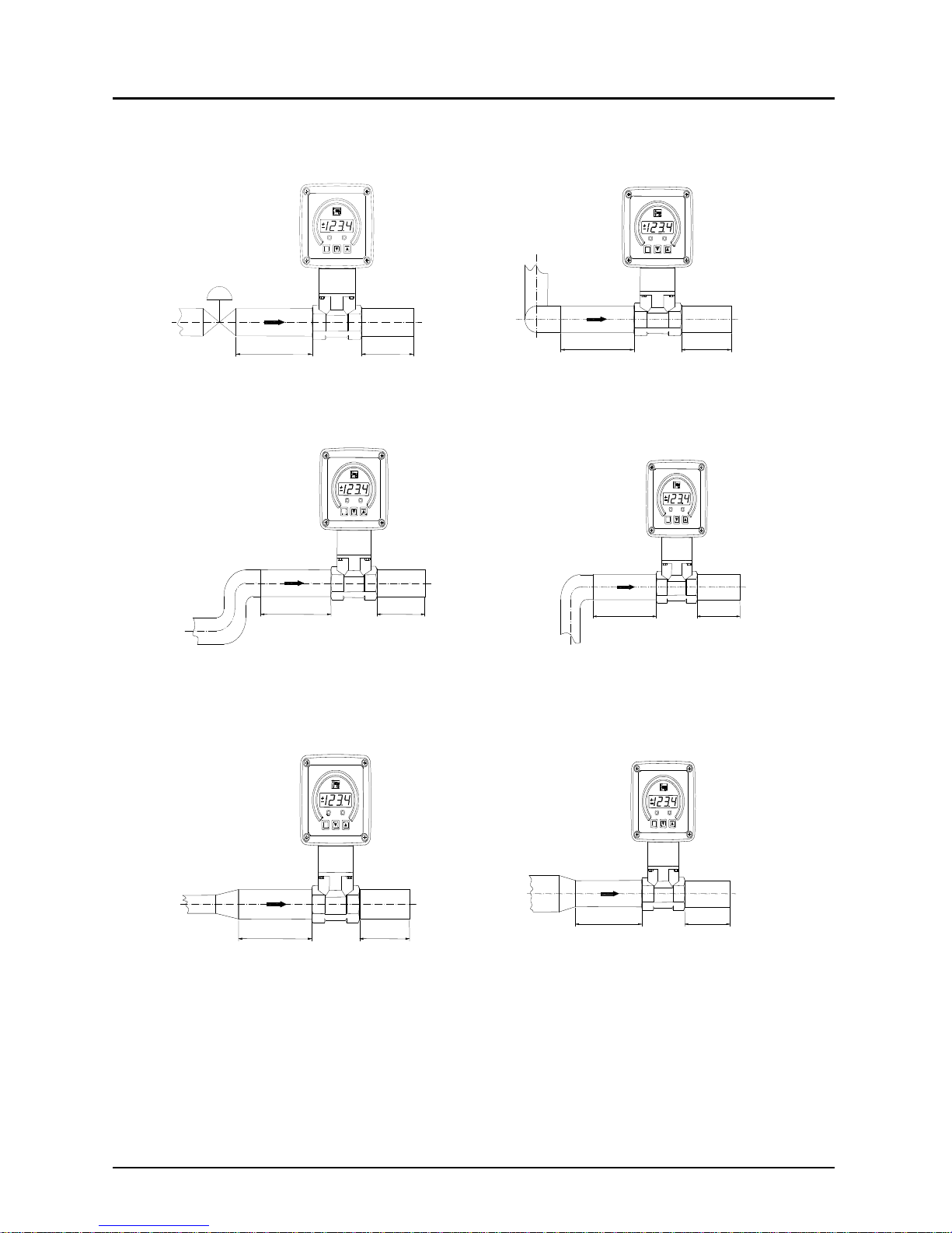
6.3. Inlet and outlet path straight piping requirements
P
50 x D 5 x D
Control valve
P
40 x D
5 x D
3 - dimensi onal
2 x 90°- el bow
P
25 x D 5 x D
2 x 90°- elbow
P
20 x D 5 x D
90°- el bow or
T - pi ece
P
18 x D 5 x D
Ext ent i on
P
15 x D 5 x D
Reducti on
Page 6
DRB
Page 6 DRB K04/0318
Version with weld-on mounting adapter
Weld the mounting adapter in the piping according to the sketch given below.
Position and weld-in the mounting adapter according to the nominal diameter
suitable marking. The marking on the adapter must be in line with the outer
diameter of the pipe. Also pay attention to the later position of the rotating vane
(shaft of the vane shifted by 90° to the direction of flow).
for DN 40
for DN 80
for DN 50
Nominal Size H
DN 25 30
DN 40 44
DN 50 46
DN 80 63
51
H
Nominal diameter
A
dapter
Ø
±
0,3
Page 7

DRB
DRB K04/0318 Page 7
7. Electrical connection
7.1. General
Attention! Make sure that the power supply voltage corresponds with the
voltage requirement of the flow meter.
Ensure that power supply is de-energized
Connect the power supply and the output signal to the plug-pins, as shown
below.
We recommend a cross-section of 0.25 mm² for the power supply cable.
Attention! Incorrect wiring may cause permanent damage to the sensor.
Page 8

DRB
Page 8 DRB K04/0318
7.2. Output Electronics:
Frequency output (..F300; ..F320, ..F340)
1
2
3
4
+Vs
Signal
Out
n.c.
GND
7.3. Output Electronics:
Analogue output (..L303, ..L342, ..L343, ..L442)
3-wire (..L303, ..L343)
1
2
3
4
+Vs
Signal
Out
n.c.
GND
+Vs
GND
2-wire (..L342)
1
2
3
4
S+
S-
n.c.
n.c.
+Vs
GND
Page 9

DRB
DRB K04/0318 Page 9
2-wire, DIN-plug (..L442)
+Vs
GND
1
2
3
S+
S-
PE
n.c.
7.4. Compact Electronics:
(..C30R, ..C30M, ..C34P, ..C34N)
see
Instruction Manual-Supplement
for Compact Electronics
7.5. Evaluation electronics: Pointer indication (..Z300, ..Z340)
1
2
3
4
+Vs
Signal
Out
n.c.
GND
+Vs
GND
Caution! If the current output is not needed, PIN 4 (signal out) shall be
permanently connected to ground (GND) (short circuit).
Page 10

DRB
Page 10 DRB K04/0318
7.6. ADI electronics
see
Instruction Manual-Supplement
for ADI-electronics
8. Commissioning – Evaluation Electronics
8.1. General
The Measuring units factory are pre-set and are ready for use after electrical
connections are made.
8.2. Adjustment – Compact electronics
see
Instruction Manual-Supplement
for Compact electronics with Frequency output
8.3. Adjustment – ADI display/controller
see
Instruction Manual-Supplement
for ADI-series display/controller
9. Maintenance
The measuring unit is maintenance-free if the medium to be measured does not
cause deposition of impurities. In order to avoid problems, we recommend
installation of a filter, such as magnet filter, model MFR.
Should cleaning of the sensor becomes inevitable, after opening the sensor the
inner parts may be accessed. Note the direction that the turbine points during
removal and re-install in the same direction. Please be careful to avoid any
damage to the sensor and in particular, to the turbine blades. Repair work
regarding electronics may only be carried out by the supplier. Any access or work
on the electronics voids the warranty.
Page 11

DRB
DRB K04/0318 Page 11
10. T echnical Data
10.1. Sensor data
Measuring range: 50-30...50-750 L/min Water
Measuring accuracy: ±3% of. f.s.
Process temperature: max. 80 °C
Ambient temperature: max. 80 °C
Max. operating pressure: PN 16 / 20 °C
Max. pressure loss: DRB-...05: 0.05 bar
DRB-...10. DRB-..15: 0.03 bar
DRB-...20: 0.04 bar
DRB-...25: 0.02 bar
DRB-...30: 0.01 bar
Protection: IP65
Materials
Housing: brass casting
st. steel 1.4581
st. steel 1.3955 (DRB...W)
Sealings: brass casting version: NBR
st. steel version: FPM
Turbine-wheel: PVDF
Axle: hard metal (DRB-11... and DRB-12...)
ceramic (DRB-1300...)
Bearing: ceramic (DRB-11... and DRB-12...)
ceramic/PEEK (DRB-1300...)
10.2. Evaluation electronics
Frequency output (F...300)
Power supply: 12 – 28 V
DC
Power consumption: 10 mA
Pulse output: PNP, open collector, max. 25 mA
Electrical connection: plug connector M12x1
Frequency output with frequency divider
Power supply: 24 V
DC
±20 %
Power consumption: 15 mA
Pulse output: PNP, open collector, max. 25 mA
Electrical connection: Plug M12x1
Division ratio: 1...1/128, factory set
Page 12

DRB
Page 12 DRB K04/0318
Analogue output (plug-on display option)
Power supply: 24 VDC ±20%
Output: 0-20 mA or 4-20 mA, 2-wire or 3-wire
Max. load: 500
Electrical connection: plug connector M12x1 or DIN 43 650
Option: plug-on display
(with plug connection DIN 43 650, 2-wire)
Compact electronics
Display: 3-segment LED
Analogue output: (0)4 -20 mA adjustable, max. 500 W
Switching outputs: 1 (2) semiconductor PNP or NPN, factory set
Contact operation: N/C / N/O contact programmable
Setting: with 2 buttons
Supply: 24 VDC ±20%, 3-wire technology,
approx. 100 mA
Electrical connection: plug connector M12x1
Pointer indication with analogue output
Housing: Aluminium
Display: moving-coil instrument,
240° display
Power supply: 24 VDC ±20 %
Output: 4-20 mA or 0-20 mA/0-10 V,
3-wire
Max. load: 250
Electrical connection: plug connector M12x1
ADI electronics
Display: bar graph, 5-digit digital display; batching unit
Analogue output: (0)4...20 mA, 0-10 V
DC
2 switching outputs: relay/changeover contact
max. 250 V
AC/5 A
resistive load, max. 30 VDC/5 A
Setting: with 4 buttons
Power supply: 100...240 V
AC ±10% or
18...30 VAC/10...40 V
DC
Electrical connection: pluggable terminal block via
cable gland
Page 13

DRB
DRB K04/0318 Page 13
DRB-...Exxx (Counter elektronic)
Display: LCD, 2 x 8 digit, illuminated
total, part and flow quantities
units selectable
Analogue output: 0(4)...20 mA adjustable
Load: max. 500
Switching output: 2 relays, max. 250 V / 5 A /1000 VA
Settings: via 4 buttons
Functions: reset, MIN/MAX memory, flow monitor,
monitoring for part and total quantity,
language
Power supply: 24 VDC ± 20 %, 3-wire
Power consumption: approx. 170 mA
Electrical connection: pluggable terminal block via
cable gland
DRB-...Gxxx (Dosing electronic)
Display: LCD, 2 x 8 digit, illuminated
total, part and flow quantities
units selectable
Analogue output: 0(4)...20 mA adjustable
Load: max. 500
Switching output: 2 relays, max. 250 V / 5 A / 1000 VA
Settings: via 4 buttons
Functions: dosing (relay S2), start, stop, reset,
fine dosing, correction amount,
flow switch, total quantity, language
Power supply: 24 VDC ± 20 %, 3-wire
Power consumption: approx. 170 mA
Electrical connection: pluggable terminal block via
cable gland
Page 14

DRB
Page 14 DRB K04/0318
11. Order Details
example: DRB-1105 G4 F300
With pipe fitting
Evaluating electronics
Frequency output
..F300= Frequency output, plug connector M12x1
..F320= Frequency divider 1:2 plug connection M12x1
..F340= Frequency divider 1:4, plug connector M12x1
..F390= Frequency divider 1…1/128 plug connector M12x1
Analogue output
..L303= 0-20 mA output, 3-wire, M12x1 plug connector
..L342= 4-20 mA output, 2-wire M12x1 plug connector
..L343= 4-20 mA output, 3-wire, M12x1 plug connector
..L442= 4-20 mA output, 2-wire, plug connection DIN EN 175301
Compact electronics*
..C30R= LED display, 2xOpen Collector, PNP, plug connector M12x1
..C30M= LED display, 2xOpen Collector, NPN, plug connection M12x1
..C34P= LED display, 4-20 mA, 1x Open Collector PNP,
plug connector M12x1
..C34N= LED display, 4-20 mA, 1xOpen collector NPN,
plug connector M12x1
Pointer indication, 240°*
..Z300= 240° pointer indication, 0-20 mA, plug connector M12x1
..Z340= 240° pointer indication, 4-20 mA, plug connector M12x1
Counter electronics
..E34R = LCD, 0(4)-20 mA, 2 x relays
Dosing electronics
..G34R = LCD, 0(4)-20 mA, 2 x relays
ADI electronics*
Measuring range
max. 3 m/s
Flow rate
max. 10 m/s
Model Connection
(L/min
water)
app.
frequency
(Hz) f. s.
(L/min water)
Mat. brass
casting
Material
st. steel
Standard
fem. Thread
Special
fem. thread
5-30
40 100
DRB-1105.. DRB-1205.. ..G4..= G 1/2 ..N4..= 1/2 NPT
10-50
40 180
DRB-1110.. DRB-1210.. ..G5..= G 3/4 ..N5..= 3/4 NPT
20-80
65 230
DRB-1115.. DRB-1215.. ..G6..= G 1 ..N6..= 1 NPT
25-250
85 600
DRB-1120.. DRB-1220.. ..G8..= G 1 1/2 ..N8..= 1 1/2 NPT
30-350
80 1000
DRB-1125.. DRB-1225.. ..G9..= G 2 ..N9..= 2 NPT
50-750
70 1600
DRB-1130.. DRB-1230.. ..GB..= G 3 ..NB..= 3 NPT
With installation adapter
not available with compact or ADI electronics
Meas.
range
(m/s)
approx.
frequency
(Hz) at
max. value
Max.
flow rate
(m/s)
Model
Connection
for nominal pipe size
..W6.. = DN 25
..W8.. = DN 40 / DN 50
..WB.. = DN 80
Material
1.3955
axle hard metal
Material
1.3955
axle ceramic
Display Power supply Output Contacts
0.7-3
0.3-3
0.3-3
0.2-3
50 (at DN 25)
85 (at DN 40)
80 (at DN 50)
70 (at DN 80)
10
DRB-1200.. DRB-1300..
K..= Bargraph/
Digital
display
0=100-240 V
AC/DC
3= 18-30 VAC,
10-40 V
DC
0= without
4= 0(4)-20 mA,
0-10 V
2= 2 change-
over contacts
*Please specify flow direction in writing
Plug-on display
For model DRB...L442 (with 2-wire, 4-20mA output and DIN plug connector)
Description Order number
4-digit LED,
connector DIN 43650,
2-wire, supply through analogue output
AUF-1000
as above
however with additional open
collector output
AUF-1001
Page 15

DRB
DRB K04/0318 Page 15
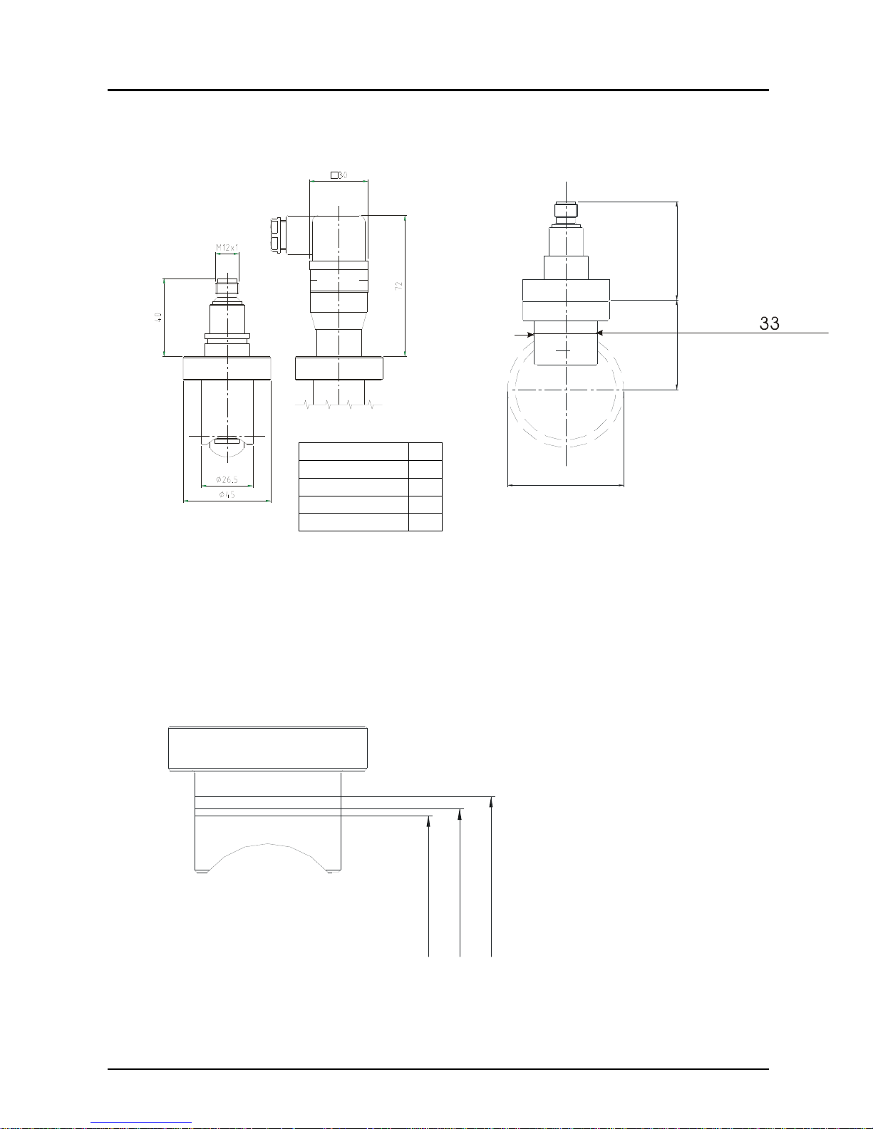
12. Dimensions (mm)
Model: DRB-...L3.. / DRB- F..
(with analogue output)
H
40
SW
51
B
G
M 12x1
Model: DRB-..L4..
(with analogue output and optional plug-on display)
G SW B H
G 1/2, 1/2 NPT 27 78 40
G 3/4, 3/4 NPT 41 78 42
G 1, 1 NPT 41 78 42
G 1 1/2, 1 1/2 NPT 55 78 57
G 2, 2 NPT 70 81 58
G 3, 3 NPT 100 106 75
Page 16

DRB
Page 16 DRB K04/0318
Model: DRB-..C.. (with Compact electronics)
Model: DRB-..Z.. (with pointer indication)
OBOLD
73
6,6
G
B
H98
SW
51
G SW B H
G 1/2, 1/2 NPT 27 78 40
G 3/4, 3/4 NPT 41 78 42
G 1, 1 NPT 41 78 42
G 1 1/2, 1 1/2 NPT 55 78 57
G 2, 2 NPT 70 81 58
G 3, 3 NPT 100 106 75
Page 17

DRB
DRB K04/0318 Page 17
Model: DRB-..K,..G.., ..E..
(with ADI evaluating electronic, counter or dosing electronic)
G SW B H
G 1/2, 1/2 NPT 27 78 40
G 3/4, 3/4 NPT 41 78 42
G 1, 1 NPT 41 78 42
G 1 1/2, 1 1/2 NPT 55 78 57
G 2, 2 NPT 70 81 58
G 3, 3 NPT 100 106 75
Page 18

DRB
Page 18 DRB K04/0318
13. EU Declaration of Conformance
We, KOBOLD-Messring GmbH, Hofheim-Ts, Germany, declare under our sole
responsibility that the product:
Turbine-wheel flow meter Model: DRB -...
to which this declaration relates is in conformity with the standards noted below:
EN 61000-6-4:2011
Electromagnetic compatibility (EMC) - Part 6-4: Generic standards - Emission
standard for industrial environments
EN 61000-6-2:2005
Electromagnetic compatibility (EMC) - Part 6-2: Generic standards - Immunity for
industrial environments
EN 61010-1:2010
Safety requirements for electrical equipment for measurement, control and
laboratory use - Part 1: General requirements
EN 60529:2014
Degrees of protection provided by enclosures (IP Code)
EN 50581:2012
Technical documentation for the assessment of electrical and electronic products
with respect to the restriction of hazardous substances
Also the following EC guidelines are fulfilled:
2014/30/EU EMC Directive
2011/65/EU RoHS
Hofheim, 08 March 2018
H. Peters M. Wenzel
General Manager Proxy Holder
 Loading...