

Page 1
Operating Instructions
for
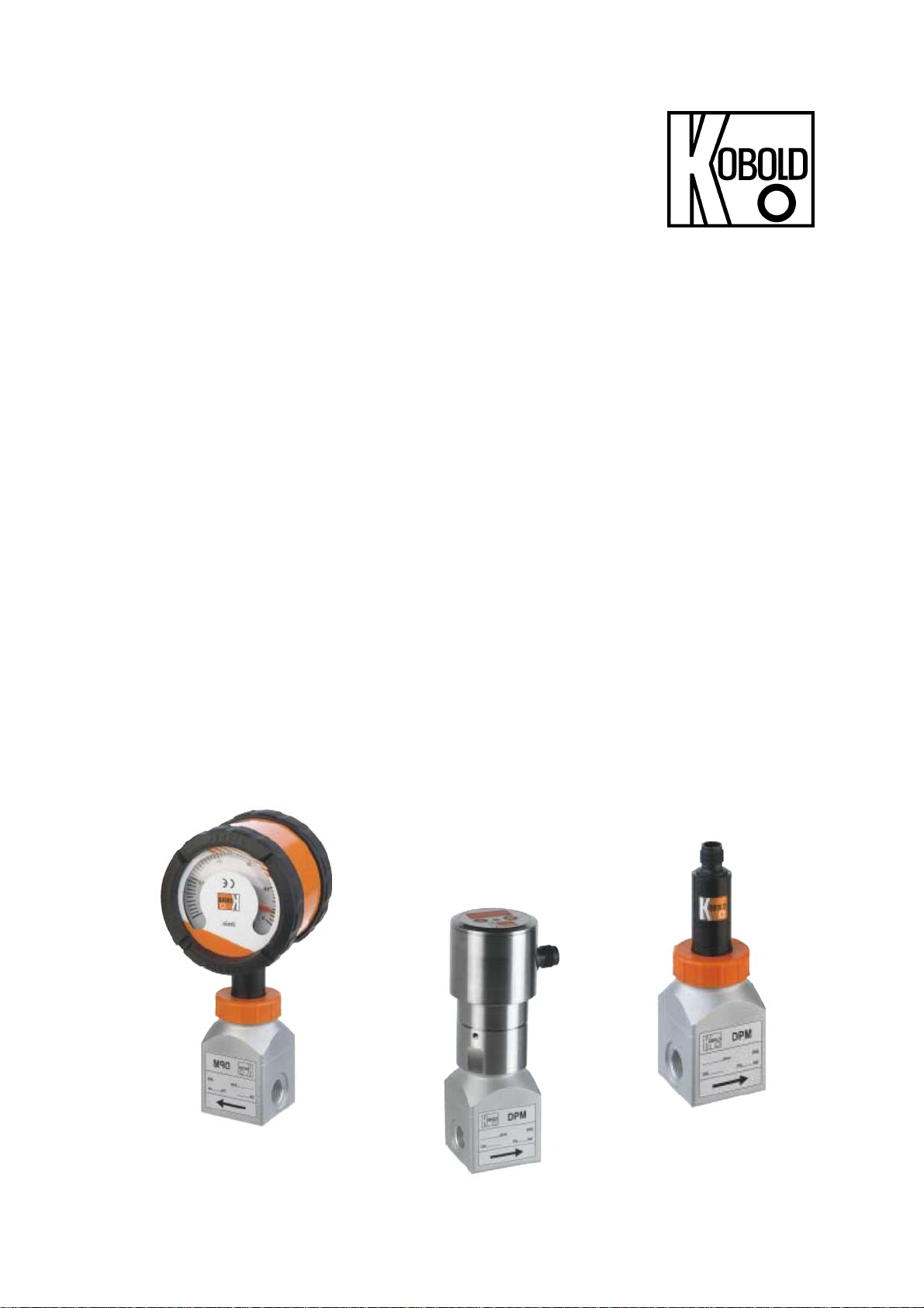
Low Volume Rotating Vane
Flow Meter
Model: DPM-...
Page 2

DPM
1. Contents
1. Contents ........................................................................................................ 2
2. Note .............................................................................................................. 3
3. Instrument Inspection .................................................................................... 3
4. Regulation Use .............................................................................................. 3
5. Operating Principles ...................................................................................... 4
6. Mechanical Connection ................................................................................. 4
6.1. Check service conditions: .................................................................... 4
6.2. Installation ............................................................................................ 4
7. Electrical Connection .................................................................................... 5
7.1. General ................................................................................................ 5
7.2. DPM...0000 (OEM without cable) ........................................................ 5
7.3. Evaluation electronics:
7.4. Evaluation electronics: Analogue output (..L..) ..................................... 6
7.5. Compact electronics: (..C30R, ..C30M, ..C34P, ..C34N) ..................... 6
7.6. Evaluation electronics: Pointer indication (..Z300, ..Z340) ................... 7
8. Operating – Evaluation Electronics ............................................................... 7
8.1. Frequency output ................................................................................. 7
8.2. Analogue output ................................................................................... 7
8.3. Compact electronics ............................................................................ 7
8.4. Pointer indication (..Z300, ..Z340) ........................................................ 7
9. Maintenance ................................................................................................. 8
10. Technical Information .................................................................................... 8
10.1. Sensor data ......................................................................................... 8
10.2. Evaluation electronics .......................................................................... 9
11. Order Codes ............................................................................................... 10
12. Dimensions (mm) ........................................................................................ 11
13. EU Declaration of Conformance .................................................................. 12
Manufactured and sold by:
Frequency output (..F300;..F320;..F340;..F380) .................................. 6
Kobold Messring GmbH
Nordring 22-24
D-65719 Hofheim
Tel.: +49(0)6192-2990
Fax: +49(0)6192-23398
E-Mail: info.de@kobold.com
Internet: www.kobold.com
Seite 2 DPM K04/0216
Page 3

DPM
2. Note
Please read and take note of these operating instructions before unpacking and
putting the unit in operation, and follow the instructions precisely as described
herein.
The devices are only to be used, maintained and serviced by persons familiar
with these operating instructions and with the prevailing regulation applying to
procedural safety and the prevention of accidents.
When used in machines, the measuring unit should be used only then when the
machines fulfil the EC-machine guide lines.
PED 2014/68/EU
In acc. with Article 4, Paragraph (3), "Sound Engineering Practice", of the
PED 2014/68/EU no CE mark.
Table 8, Pipe, Group 1 dangerous fluids
3. Instrument Inspection
These devices are checked before dispatch and shipped in perfect condition.
Should damage to a device be visible, we recommend a thorough inspection of
the delivery packaging. In case of signs of damage to the packaging, please
inform your parcel service/forwarding agent immediately, since they are
responsible for damages during transit.
Scope of delivery:
Low Volume Rotating Vane Flow Meter model: DPM
Operating Instructions
4. Regulation Use
Any use of the Rotating Vane Flow Meter, model DPM, which exceeds the
manufacturers specification may invalidate its warranty. Therefore, any resulting
damage is not the responsibility of the manufacturer. The user assumes all risk
for such usage.
DPM K04/0216 Seite 3
Page 4

DPM
5. Operating Principles
KOBOLD model DPM flow meters are used for measuring and monitoring liquids.
Due to its compact construction the measuring instrument is suitable for use with
machines with minimum available space. The system can be used in a wide
variety of applications because the output pulses can be analysed in many
different ways.
The medium flows though a specially shaped housing nozzle and causes a vane
to rotate. This rotary motion is sensed by optoelectronics in a non-contacting
manner, and converted to an pulse frequency signal or an analogue signal. A
frequency divider with pulse output is available as an option. The frequency is
proportional to the flow velocity. The vane is sapphire-supported, this ensures a
high degree of linearity and long service life.
6. Mechanical Connection
6.1. Check service conditions:
flow
max. operating pressures
max. service temperature
Attention! Overrange can cause damage to bearings and major
measuring errors
6.2. Installation
flow in direction of arrow (universal)
avoid pressure and tensile loads, mechanically fix inlet and outlet lines at
distances of 50 mm from the connections
check connections for leaks
Seite 4 DPM K04/0216
Page 5

DPM
7. Electrical Connection
7.1. General
Attention! Make sure that the voltages in your plant correspond with
the flow meter voltages.
Make sure that the electrical supply lines are dead.
We recommend a power supply cable with cross sectional area of 0.25 mm².
Attention! The instrument electronics may be damaged if the cable
connections are wired incorrectly.
7.2. DPM...0000 (OEM without cable)
Feed voltage receiver 4,5 ... 16 VDC
+ VS
Si g n a l
2
Re c e i v e r
5
Tra nsm it te r
Transm. Re ceiv er
3
GND
4
1
+ VS
Feed current receiver typ. 7 mA
Signal amplitude High approx. operating voltage
Signal amplitude Low 0,2 V
Reverse voltage transmitter 3,0 V max.
Feed current transmitter 8 ... 12 mA
Output dissipation (power) 2,5 mW max.
1
2
3
4
5
Signal
VS RV*
5 V
8 V
12 V
470 / 0,25 W
820 / 0,25 W
1300 / 0,25 W
* Not included in
delivery.
DPM K04/0216 Seite 5
Page 6

DPM
7.3. Evaluation electronics:
Frequency output (..F300;..F320;..F340;..F380)
n.c.
GND
2
3
1
4
+Vs
Signal
Out
7.4. Evaluation electronics: Analogue output (..L..)
3-wire (DPM-..L303, ..L343) 3-wire, DIN 43650 plug connector
(DPM-..L403, ..L443)
+Vs
2
1
4
+Vs
Signal
Out
GND
n.c.
GND
3
+Vs
+Vs
Signal
Out
GND
7.5. Compact electronics: (..C30R, ..C30M, ..C34P, ..C34N)
See supplement Operating Instructions
for compact electronics with frequency output
GND
Seite 6 DPM K04/0216
Page 7

DPM
7.6. Evaluation electronics: Pointer indication (..Z300, ..Z340)
+Vs
2
1
n.c.
Po w e r
+Vs
Plug M 12
GND
GND
3
4
Signal
Out
8. Operating – Evaluation Electronics
8.1. Frequency output
The measuring instruments are ready for operation after electrical connection.
8.2. Analogue output
The measuring instruments are ready for operation after electrical connection.
8.3. Compact electronics
The measuring instruments are factory programmed and ready for operation after
electrical connection.
(To change the settings see Operating Instructions supplement for compact
electronics with frequency output)
8.4. Pointer indication (..Z300, ..Z340)
The measuring instruments are ready for operation after electrical connection.
DPM K04/0216 Seite 7
Page 8

DPM
9. Maintenance
The measuring instrument requires no maintenance if the measured medium is
clean. To prevent coating the sensor optics, we recommend that a filter is
installed, for example the magnetic filter, model MFR.
If the sensor has to be cleaned, then it can be opened to gain access to the
inside parts. Make sure that the sensor and especially the blades are not
damaged. When re-assembling, make sure that the vane is positioned and
oriented correctly.
Work on the sensor and electronics should only be carried out by the supplier,
otherwise the guarantee is nullified.
10. T echnical Information
10.1. Sensor data
Measuring accuracy:
DPM..000, F300 ± 2.5% f. s.
DPM...L, ...C, ...Z: ± 1% f. s.
Linearity: ± 1% f. s.
Repeatability: 0.5%
Medium temperature: -40… +80 °C
Ambient temperature: -30… +60 °C
Max. operating pressure: 16 bar
Protection: IP 65
Materials:
Case: brass nickel-plated
stainless steel 1.4404
Upper part: brass nickel-plated
stainless steel 1.4404
Union nut: brass nickel-plated
stainless steel 1.4305
Nozzle: stainless steel 1.4405
Axle: sapphire
Vane: polypropylene
Vane mount: polysulfone
Gasket: NBR (standard)
FPM or EPDM (optional)
Seite 8 DPM K04/0216
Page 9

DPM
10.2. Evaluation electronics
Frequency output (OEM)
Power supply: 4.5-12 V
Supply current: typically 7 mA
Signal amplitude high: approximately power supply
Signal amplitude low:
0.2 V
Cut-off voltage transmitter: 3 V max.
Supply current transmitter: 8-12 mA
Output loss: max. 2.5 mWatt
Pulse output: NPN, open collector, max. 10 mA
Electrical connection: solder pins
Frequency output (frequency divider option)
Power supply: 24 V
DC
Supply current: 40-50 mA
Pulse output: PNP, open collector, max. 20 mA
Signal amplitude high: power supply level approximately
Signal amplitude low:
0.2 V
Output loss: max. 2.5 mWatt
Pulse output: PNP, open collector, max. 20 mA
Electrical connection: plug connector M12x1
Division ratio (option): 1...1/128, factory setting
Analogue output (plug-on display option)
Power supply: 24 V
DC
Output: 0-20 mA or 4-20 mA, 3-wire
Max. load: 500
Electrical connection: plug connector M12x1 or DIN 43 650
Option: plug-on display
(with plug connector DIN 43 650 only)
Compact electronics
Display: 3-segment LED
Analogue output: (0)4 – 20 mA adjustable, max. 500
Switching outputs: 1 (2) semiconductor PNP or NPN, factory set
Contact operation: N/C / N/O contact programmable
Setting: with 2 buttons
Supply: 24 V
DC
Power input: approx. 100 mA
Electrical connection: plug connector M12x1
DC
±20%
±20%
± 20%, 3-wire technology
DPM K04/0216 Seite 9
Page 10

DPM
Pointer indication with analogue output
Case: aluminium (PA6 GF30)
Display: moving coil instrument, 240° display
Power supply: 24 V
Output: (0)4…20 mA, set at the factory,
3-wire technology
Max. load: 250
Electrical connection: plug connector M12x1
11. Order Codes
Order Details (example: DPM-1107 G1 0000)
Meas.
range
L/min
water
approx.
frequency
Hz at
max. value
approx.
pressure
loss bar at
max. value
Material
brass
Model
Material
st. steel
± 20 %
DC
Connection Electronic analyser
0.015 - 0.3 165 0.93
0.05 - 0.7 228 1.16
0.05 - 1.0 217 0.53
0.05 - 2.0 344 0.91
0.05 - 3.0 372 0.61
0.05 - 4.0 415 0.57
0.05 - 5.0 439 0.57
DPM-1103 DPM-1503..
DPM-1107.. DPM-1507..
DPM-1110.. DPM-1510..
DPM-1120.. DPM-1520..
DPM-1130.. DPM-1530..
DPM-1140.. DPM-1540..
DPM-1150.. DPM-1550..
G1.. = G 1/8 fem.
G2.. = G 1/4 fem.
N1.. = 1/8 NPT fem.
N2.. = 1/4 NPT fem.
Frequency output, without CE
..0000 = Frequency output, without cable (OEM), NPN
..F300 = Frequency output, plug connector M12x1, PNP
..F320 = Frequency divider 1:2, plug connector M12x1, PNP
..F340 = Frequency divider 1:4, plug connector M12x1, PNP
..F390 = divider 1...
..L303 = 0 - 20 mA output, 3-wire, M12x1 plug connector
..L343 = 4 - 20 mA output, 3-wire, M12x1 plug connector
..L403 = 0 - 20 mA output, 3-wire, plug connector DIN 43 650
..L443 = 4 - 20 mA output, 3-wire, plug connector DIN 43 650
Compact electronics*
C30R = LED display, 2x open collector, PNP, plug connector M12x1
C30M = LED display, 2x open collector, NPN, plug connector M12x1
C34P = LED display, 4 - 20 mA, 1x open coll., PNP, plug connector M12x1
C34N = LED display, 4 - 20 mA, 1x open coll., NPN, plug connector M12x1
Z300 = 240° Pointer indication, 0 - 20 mA, plug connector M12x1
Z340 = 240° Pointer indication, 4 - 20 mA, plug connector M12x1
1
/128, plug connector M12x1, PNP
Analogue output
Pointer indication*
*Please specify flow direction in writing
Plug-on display
for model DPM...L443 (with 4-20 mA output and DIN plug connector)
Description Order number
3-position LED, Plug connector DIN 43 650,
3-wire, Power supply through analogue output
AUF-3000
Seite 10 DPM K04/0216
Page 11

DPM
12. Dimensions
DPM-...F DPM-..L3 DPM-..C
with frequency output with analogue output with compact
electronics
44,5
M12x1
113, 5
M4
D
32
40
13
12,5
M4
D
M12x1
113, 5
13
12,5
32
40
M4
D
32
40
OBOLD
23,7
13
12,5
12
47
DPM-..L with analogue out DPM-..Z wi th analogue output
and plug-on display and pointer indication
6,6 73
130
79,7
M12x1
168
M4
D
32
13
12,5
11, 5
40
M4
D
32
40
161
13
12,5
DPM K04/0216 Seite 11
Page 12

DPM
13. EU Declaration of Conformance
We, KOBOLD-Messring GmbH, Hofheim-Ts, Germany, declare under our sole
responsibility that the product:
Low Volume Rotating Vane Flow Meter model: DPM-...
to which this declaration relates is in conformity with the standards noted below:
EN 61000-6-4:2011-09
Electromagnetic compatibility (EMC) - Part 6-4: Generic standards - Emission
standard for industrial environments
EN 61000-6-2:2005
Electromagnetic compatibility (EMC) - Part 6-2: Generic standards - Immunity for
industrial environments
EN 61010-1:2011-07
Safety requirements for electrical equipment for measurement, control and
laboratory use - Part 1: General requirements
EN 60529:2014-09
Degrees of protection provided by enclosures (IP Code)
Also the following EC guidelines are fulfilled:
2014/30/EU EMC Directive
2011/65/EU RoHS (category 9) industrial monitoring and control
instruments, compliant, no CE-marking for the transitional
period until 2017
Hofheim, 18. Feb. 2016
H. Peters M. Wenzel
General Manager Proxy Holder
Seite 12 DPM K04/0216
 Loading...