

Page 1

K03/1213
Manufactured and sold by:
Kobold Messring GmbH
Nordring 22-24
D-65719 Hofheim
Tel.: +49(0)6192-2990
Fax: +49(0)6192-23398
BI-DIRECTIONAL INSERTION FLOW TRANSDUCER
Model DOR
INSTRUCTION MANUAL
KOBOLD
LOCK
Page 2

IMPORTANT INFORMATION
Thank you for purcha
sing a Kobold Insertion Flowmeter. It is important that you
read this manual to gain a full understanding of the capability and operational
aspects of the equipment you are about to install.
This information is provided only to assist in the installation of the product and
does not diminish your obligation to read the manual.
1. Select a location that meets the requirements as illustrated on the guideline
sheet (please see the data sheet/order codes). An ideal installation would provide
for 25 diameters of straight pipe upstream from the meter and 10 diameters
downstream.
You will also need to know the pipe internal diameter (NB) and pipe wall thickness
for calculation of the insertion depth. (refer page 5.) Non ideal installations may
require in-situ calibration (refer to the factory for details).
2. After screwing the flowmeter in place ensure the flow alignment mark located
on the top positioning collar of the meter aligns with the flow in the pipe (refer
page 5). This ensures the paddle is correctly aligned to the flow.
Note. the meter is bi-directional so a flow direction arrow is not provided.
3. Calculate and adjust the height of the flowmeter (refer page 5).
4. Electrical Installation depends on the model you have purchased.
If the dualpulse is fitted or supplied with a receiving instrument such as a totaliser
or rate totaliser please refer to the appropriate manual and page 10 of this
manual. For pulse output meters, select the appropriate output and wire to your
receiving device. (refer pages 7 to 9).
5. Calculate the flowmeter K (scale) factor to suit the installation. For ideal
installations refer to page 11 or 12 or 13 of the flowmeter Manual. For non ideal
installations the K-factor may be calculated by performing an in-situ calibration.
Enter the appropriate K-factor into your receiving instrument.
page 1
CONTENTS PAGE
1.0 INTRODUCTION
1.1 Model number designation
1.2 Overview
1.3 Operating principal 3
1.4 Specifications 3
2.0 INSTALLATION
2.1 Meter location
2.2 Meter installation & orientation 4
2.3 Height adjustment 5
2.4 Flow direction orientation 5
2.5 Hot tap installations 6
3.0 ELECTRICAL CONNECTIONS
3.1 Standard outputs 7
3.2 Optional Reed switch output 7
3.3 Instrument cable installation requirements 8
3.4 Pulse output selection ( standard outputs ) 8
3.5 QP Quadrature pulse output option 9
3.6 Bi-directional flow using QP option 9
3.7 Connection to family instruments 10
4.0 K – FACTOR ( calibration factor for meter )
4.1 K-factors for common pipe ID sizes <575mm 11
4.2 K-factors for large pipe ID >460mm 11
4.3 Calculating K-factors ( metric units – litres or M3 ) 12
4.4 Calculating K-factors ( US gallons )
5.0 Declaration of Conformance
3
4
12
14
Page 3

Page 2
1.1 Model no. designation
Please see the data sheet
1.2 Overview
Kobold insertion flow transducers provide a cost effective and simple means of measuring
the flow of a wide range of low viscosity liquids. Installation is quick and inexpensive for
pipe diameters ranging from 40mm to 900mm (1.5-36") and up to 2500mm (100") nominal
bore for the Hot tap capable model DOR-52.
The flowmeter has a linear measuring range of 0.3~10.0 metres/sec. (1~33 ft/sec.).
Minimum detectable flow velocity is 0.15 m/sec. (0.5 ft/sec.). When used in conjunction with
the ZOD-Z3 flow rate totaliser NLC feature the linear flow range is extended down to 0.15
m/sec. (0.5 ft/sec.) with an improved linearity.
The flowmeter is constructed from 316 L (1.4404) stainless steel enabling use in many
applications for metering water and low viscosity chemicals.
Two independent pulse outputs are standard & can directly input to a wide range of
ancillary instruments, PLC’s and computers. Both pulse outputs have a high level of
immunity to electrical interference. Options include a reed switch.
1.3 Operating principle
Flow passes through a pipe causing the rotor to spin. Magnets installed in the rotor pass by
pulse sensors within the transducer body & inturn this produces frequency outputs
proportional to flow rate.
page 3
1.4 Specifications
Velocity measuring range (linear): 0.3...10 m/s equates to approx.0.25...49,000 l/s in
Linearity: ±1.5% with well est. flow profile
Repeatability: ±1% of f. s. at factory conditions and optimal straight
Max pressure: 80 bar
Temperature range: -40…+100°C standard, see max.allowable medium
Material
Body: stainless steel 1.4404 (316L)
Rotor: PVDF or PEEK (depending on model)
Rotor shaft: stainless steel 1.4404 (316L)
Bearing: graphite/PTFE
Seals: FPM (standard): -15…+200°C
EPR (ethylene propylene rubber): -20…+120°C, for
PTFE encapsulated FPM: -20…+200°C
NBR (Nitril): -65…+125°C
Electronics
Output frequency at max. velocity: 220...240 Hz (hall effect and voltage output),
73...80 Hz (reed switch output)
Supply voltage: see electrical output specifications and electronics
Electronic features: see electronics comparison table in the data sheet
Wiring (standard): 5 core, screened cable, length 3 meters
Transmission distance: 1,000 meters maximum, without integrated electronics
Cable entry (terminal box): M20x1.5 (standard), 1/2“ NPT adapter (optional)
Protection Class: IP68 (cable connection),
IP66/67 (all other electrical connections)
Straight piping requirement: Minimum: 10xd (upstream), 5xd (downstream)
Optimal: 25xd (upstream), 10xd (downstream)
Weight: (approx., without electronics):
1.6 kg (DOR-4), 2.5 kg (DOR-5)
DN40 to DN2500 pipes; 0.15...10 m/s when using the
linearisation function of electronic type Z3
runs
temperature table for other options and restrictions
ketones only
comparison table in the data sheet
Page 4
page 4
page 5
2.0 INSTALLATION
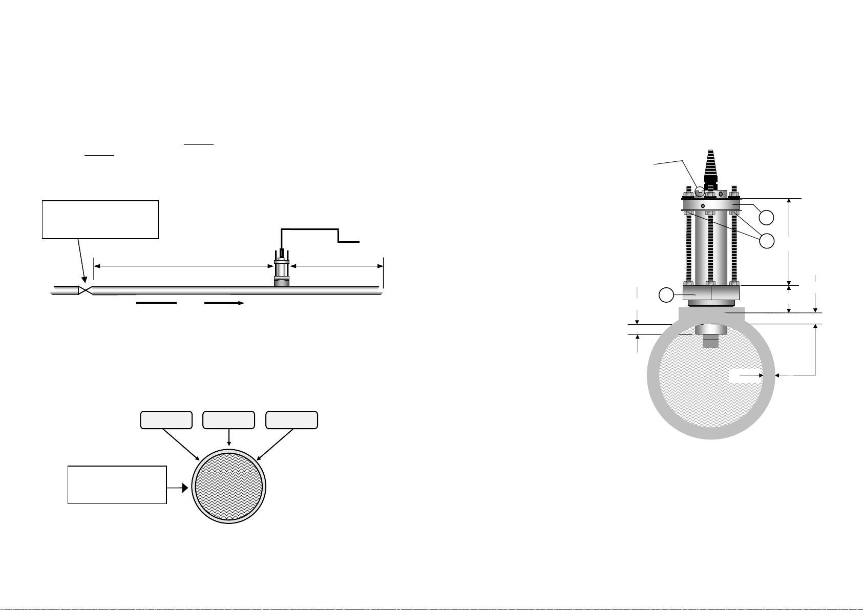
2.1 Meter location
Choose an appropriate section of horizontal or vertical pipe as per the guidelines below.
With vertical pipe installations the media should be pumped up through the pipe past the
flow sensor so that any entrained air will pass freely.
The DOR flow sensor requires a fully developed turbulent flow profile to ensure maximum
measurement accuracy and repeatability. This can be achieved by installing the DOR in a
straight run of pipe. We recommend at least 10 but ideally 25 straight pipe diameters
upstream & at least 5 but ideally 10 pipe diameters downstream of the flowmeter. Major
obstructions such as pumps, valves or strainers will require longer straight runs before and
after the flowmeter.
Major obstructions such as
pumps,valves,reducers or strainers
to be kept well outside the straight
run pipe sections
10 pipe dia. minimum
25 pipe dia. prefered
FLOW
5 pipe dia. min.
10 pipe dia. prefered
2.3 Height adjustment calculation
Calculate the adjustment height A for DOR-42 (or AA for the DOR-52) as follows:
A ( for DOR-42 ) = 175mm ( 6.9") - ( B + C + D )
AA ( for DOR-52 ) = 420mm (16.5") - ( B + C + D )
Where :
B = Distance between the top of the pipe & the top of the hex adaptor.
C = Pipe wall thickness
D = Insertion depth ( pipe ID ÷ 8 )
ALIGNMENT SLOT TO
PARRALLEL PIPE
LOCK
Examples of insertion depth D :
For 40mm pipe ID ( D= 5.0 mm )
For 50mm pipe ID ( D= 6.25 mm )
3
1
A (AA)
For 100mm pipe ID ( D= 12.5 mm )
For 400mm pipe ID ( D= 50.0 mm )
2
D
B
C
2.2 Meter installation & orientation
Cut a 40mm diameter hole (1.6") on either the 2, 10 or 12 o’clock positions of the pipe. If
there is any likelihood of air entrainment in a horizontal pipe do not locate the flow
transducer in the 12 o’clock position.
12 o’clock
2 o’clock
Other positions
around the pipe are
ptable
acce
Install a female threaded weld on fitting (threadolet) or service saddle.
Wrap the threads of the flowmeter with PTFE tape or sealing compound & screw the unit
into the installed fitting.
C
Turn the height adjustment nuts (1) as required so that the distance between the top of the
hex adaptor (2) and the top of the positioning collar (3) equals your calculated distance A
(for DOR-42) or AA for model DOR-52. Retighten the height adjustment nuts (1).
2.4 Flow direction orientation
The unit is bi-directional however the paddle must be aligned with the direction of flow.
Using a 2mm hex key (Allen key), unlock the locking screw located on the positioning collar
(3) then insert the hex key (as a lever) in the body rotating hole located above the collar,
turn the body until the alignment slot is parallel with the direction of pipe. Retighten the
locking screw.
Page 5
page 6
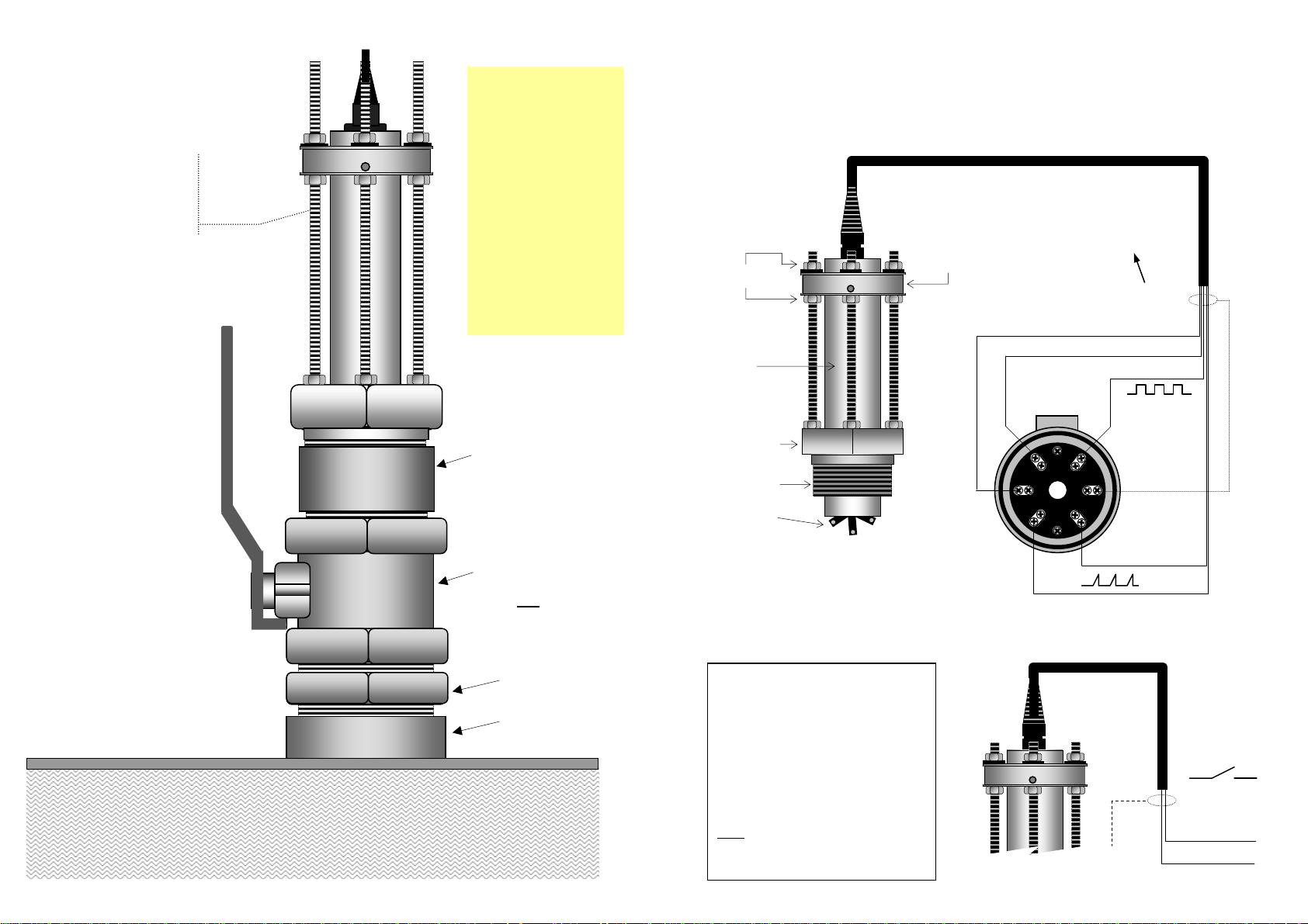
2.5 Hot tap installation
( model DOR-52 )
Clean & lubricate screw
threads before
withdrawing the
transducer body in order
to avoid nut seizure
IMPORTANT
Before removing the
DOR-52 from the
installation first
withdraw the
transducer body to
the maximum
distance allowed by
the three height
adjusting threaded
rods. This will enable
the isolating valve
to be fully closed
without damaging the
paddle.
If necessary extend valve
port using a 2” nipple &
socket combination to
ensure the paddle is clear
of the ball valve.
CAUTION : Hot tap installation
should only be performed by
qualified personal. Installation
procedures should be in accordance
with the safety rules, regulations and
requirements applying to the territory
in which the flow transducer is being
installed.
2" ball or gate
isolation valve.
(Allow min. 40mm I.D. to
clear metering head)
2" Nipple
2" Weld-O-let
( threadolet )
FLOW
Hot tap clearance hole in
pipe wall to be a minimum
of 40mm diameter (1.6").
page 7
3.0 ELECTRICAL CONNECTIONS
( see page 9 for QP outputs )
3.1 Standard outpu
ts
Conductor color coding also applies to the Non-magnetic
sensor and high temperature output options
Height
adjustment
Body
KOBOLD
LOCK
Positioning
collar
Pull up resistor
required, they are
generally incorporated
in most receiving
instruments
SQUARE WAVE
PULSE OUTPUT
Black ( -0v ground )
Red ( VDC supply )
White ( + Sig. output )
Hex adaptor
1.5” or 2” BSPT
or NPT
Rotor
Terminal box option
terminal connections
b1
A1
A2
B2 B1
VOLTAGE PULSE
Screen
OUTPUT
Yellow ( + )
Green ( - )
3.2 Optional Reed switch output
The REED SWITCH output is classed as a
“simple apparatus“ as defined in the
CENELEC standard EN50020 &
recognized ATEX directive. It can be
connected to an approved I.S. secondary
instrument with both being located in the
hazardous area.
The Reed Switch may also be connected
through an approved I.S. barrier.
Note: The Reed switch produces 1/3
( eg. 1/3 the standard K-factor )
HAZARDOUS AREAS
the normal pulse output value
KOBOLD
LOCK
rd
Screen
To -0V
REED SWITCH
OUTPUT
Yellow
Green
Page 6
page 8
3.3 Instrument cable installation requirements
Use twisted multi-core low capacitance shielded instrument cable (22 AWG ~ 7x 0.3
stranded) for electrical connection between the flow meter and the remote instrumentation.
The screen should be earthed at the readout instrument end only to protect the transmitted
signal from mutual inductive interference.
The cable should not be run in a common conduit or parallel with power and high inductive
load carrying cables as power surges may induce erroneous noise transients onto the
transmitted pulse signal. Run the cable in separate conduit or with other low energy
instrument cables .
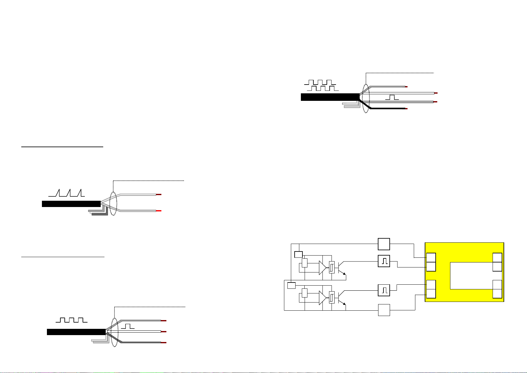
3.4 Pulse output selection ( standard outputs )
The standard flowmeter has two independent pulse output signals that are linearly
proportional to volumetric flow rate. Pulse transmission can be up to 1000 metres (3300 ft ).
An optional I.S. Reed Switch output is available (see page 7).
Voltage pulse (pulse wire) output
A self generating pulse output which produces a strong 1.5 volt voltage spike of
approximately 10 micro/second duration with no dependence on rotor speed.
Screen
Yellow ( + )
Green ( - )
Square Wave Pulse (Hall sensor) ( also applies to non-magnetic & QP Hall outputs )
An NPN open collector transistor pulse output produced by a solid state Hall Effect device.
This three wire device requires 5~24vdc and produces an NPN square wave output (20mA
max. sink), pulse width is 2~75 mSec. The Hall output requires a pull up resistor, these are
generally incorporated in most receiving instruments. For (QP) Quadrature pulse output
refer details page 9.
(5-24vdc supply )
signal output
( -0v ground )
Screen
Red
White
Black
Page 9
3.5 Quadrature outputs
DOR series flow meters supplied with the QP option produce two NPN open collector pulse
outputs from two Hall Effect sensors. The outputs are “ phase offset ” in their timing so that
external electronics are able to differentiate. These outputs may be used to assure output
signal integrity or to measure bi-directional flow.
Red ~ Vdc
Black ~ -0V
Screen
White ~ output 1
Blue ~ output 2
3.6 Bi-directional flow
The DOR flow transducer is capable of accurately measuring flow in both directions without
modification. Meters fitted with the QP output option (quadrature pulse output) may be
interfaced with the Pulse Discriminator Module (PD2). The PD2 accepts the Quadrature
pulse inputs & from these will discriminate between forward & reverse flow. Two individual
& proportional pulse outputs can then be sent to appropriate totalising registers or an Z3
add and subtract flow rate totaliser.
It is important to note that the Quadrature Pulse option has the same pulse resolution
(pulses/unit volume) as a standard flowmeter for both forward & reverse outputs.
Flowmeter with QP outputs
Reg
X
Reg
X
5~24Vdc maximum
Output Signal 1
(forward flow)
Output Signal 2
(reverse flow)
Vdc
+
+
PD2 Pulse Discriminator
10
Sig.1
9
Sig.2
7
6
+Vdc
-0V
+8~24Vdc
Forward flow Sig.
Output signals
Reverse flow Sig.
-0V
5
4
2
1
Ground
-0V
Page 7
page 10
)
)
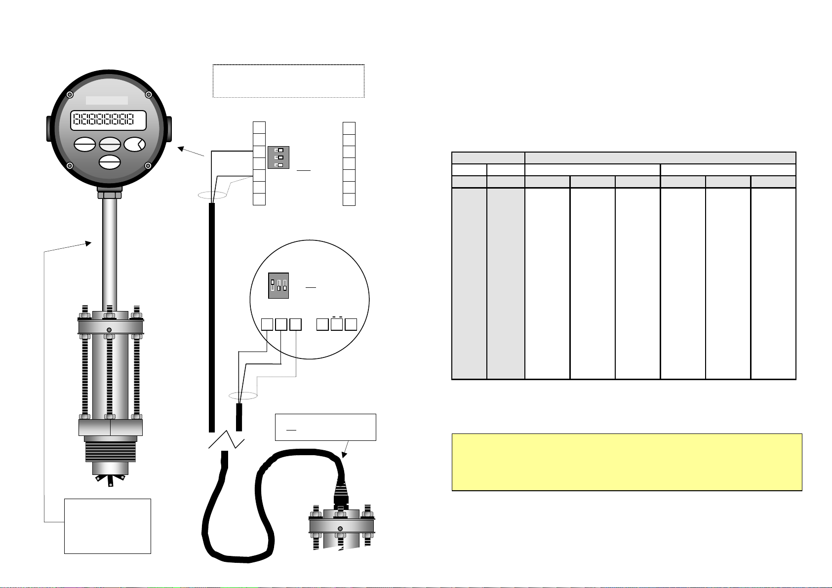
3.7 Voltage Pulse Connection to family instruments
RATE TOTALISER
RUN ACCUM. TOTAL STOP BAT LOW
RESET
PROGRAM
ENTER
>
RATE
TOTAL
ACCUM
TOTAL
gal
^
Note: For other output styles see
receiving instrument manual
Z3 & B1 SERIES
yellow
green
Screen
1
INSTRUMENTS
2
3
3
O
2
N
4
1
-0V (ground)
5
6
7
All flow DIP
switches in the
position
OFF
14
13
12
11
10
9
8
KOBOLD
LOCK
yellow
green
Z1 TOTALISER
ON
1 2 3
1 2 3
-
+
1 2 3
DIP switch 1 in
the ON
position
( 2 Khz max.)
gnd
+Vdc
4 5 6
+∏
-gnd
Screen
The flowmeter cable should
not
be run with other high
energy cables ( clause 3.3 ).
Flow instruments or a
terminal box can be
directly mounted to the
flowmeter using ST4 (for
DOR-42) or ST5 (DOR-
52) mounting stem kits
FLOMEC
LOCK
page 11
4.0 K – FACTORS ( calibration factors for meter )
The K-factor (pulses / litre, gallon etc.) will vary in relation to the bore size of the pipe in
which the flowmeter is installed.
The K-factors and formula shown are a result of factory testing using smooth bore piping
under ideal conditions. Variations to the given K-factors may occur when using rough bore
piping or inadequate flow conditioning on either side of the flow transducer (refer clause
2.1). In these instances on site calibration may be used to determine the K-factor.
4.1 Flow transducer K- factors for common pipe sizes
Pipe detail
NB ID (#40)
K-factors
Schedule 40 pipe - (#40
inches mm p / litre p / m3 p / USgal p / litre p / m3 p / USgal
1.5" 40.9 18.678 18678 70.695 21.524 21524 81.468
2" 52.6 11.238 11238 42.534 12.818 12818 48.517
2.5" 62.7 7.880 7880 29.824 8.899 8899 33.682
3" 78.0 5.062 5062 19.161 5.676 5676 21.485
3.5" 90.2 3.768 3768 14.263 4.200 4200 15.896
4" 102 2.912 2912 11.021 3.233 3233 12.237
5" 128 1.839 1839 6.959 2.025 2025 7.665
6" 154 1.268 1268 4.798 1.402 1402 5.307
8" 203 0.719 719.0 2.721 0.787 787.2 2.980
10" 255 0.450 450.3 1.705 0.496 495.9 1.877
12" 303 0.316 316.0 1.196 0.347 347.4 1.315
14" 333 0.261 260.5 0.986 0.286 285.7 1.081
16" 381 0.198 198.0 0.750 0.217 217.0 0.821
18" 429 0.156 155.8 0.590 0.171 170.6 0.646
20" 478 0.125 125.4 0.475 0.138 137.8 0.521
24" 575 0.087 86.64 0.328 0.095
For other pipe sizes below 610mm (24") not listed above, use the graphs and apply the
formula on the following pages ( 12 & 13 ).
4.2 K-factors for large pipes 460mm ID (18") and above use:
Pulses per litre = 28647 ÷ pipe ID² (mm)
Pulses per M³ = 28647000 ÷ pipe ID² (mm)
Pulses per US gallon = 168.14 ÷ pipe ID² (inches)
Pulses per Imp. gallon = 201.94 ÷ pipe ID² (inches)
( standard K-factors for voltage & square wave outputs )
Schedule 80 pipe - (#80
95.39 0.361
NOTE : K-factors for Reed Switch output option are 1/3 the standard factors of voltage
pulse output.
Page 8
page 12
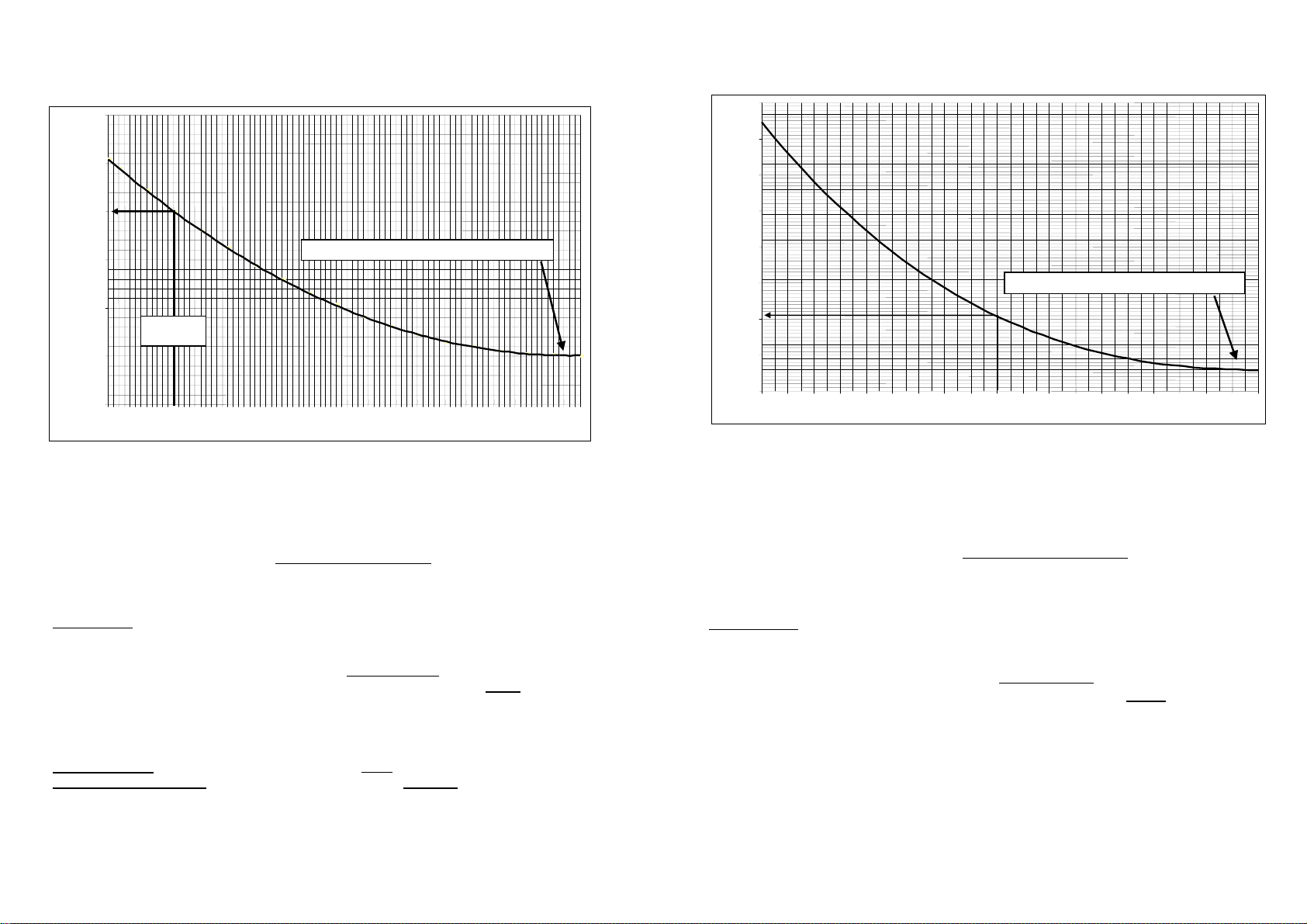
4.3 Calculating K-factors ( litres or m³ )
25
24.5
24
(A)
23.5
Pipe ID 450mm & above (A) = 22.5
23
See
example a
22.5
22
40 60 80 100 120 140 160 180 200 220 240 260 280 300 320 340 360 380 400 420 440 460
pipe ID (mm)
Calculate K-factor ( pulses / litre ) using the above graph and the metric constant of 1273.2
as follows :
Pulses / litre = 1273.2 x (A) from graph
pipe ID² (mm)
Example ‘a’ :
K-factor for 100mm pipe: 1) from graph 100mm ID (A) = 24.0
2) pulses/litre. = 1273.2 x 24.0
10000 = 3.056 p/litre
K-factor for m³ : multiply by 1000 eg. K = 3056 p/m³
K-factor for megalitres : multiply by 1000000 eg. K = 3056000 p/megalitre
NOTE : K-factors for Reed Switch output option are 1/3 the standard factors of voltage
pulse output.
page 13
4.4 Calculating K-factors ( US gallons )
7.6
7.5
7.4
7.3
7.2
(A)
7.1
Pipe ID 19.5 ” & above (A) = 6.86
7.0
6.9
6.8
12345678 91011 12 13 14 15 16 17 18 19 20
pipe ID
(inches)
Calculate K-factor ( pulses / gallon ) using the above graph and the volumetric
constant of 24.51 as follows :
Pulses / US gal. = 24.51 x (A) from graph
pipe ID² (inches)
Example ‘b’ :
K-factor for 10" pipe: 1) from graph 10" ID (A) = 7.01
2) pulses/gal. = 24.51 x 7.01
100 = 1.718 p/gal
NOTE :
K-factors for Reed Switch output option are 1/3 the standard factors of voltage pulse output.
Page 9

page 14
5.0 Declaration of Conformance
We, KOBOLD Messring GmbH, Hofheim-Ts, Germany, declare under our sole responsibility that the product:
Bi-Directional Insertion Flow Transducer Model: DOR
to which this declaration relates is in conformity with the standards noted below:
97/23 EC Pressure Equipment Directive
Pressure Accessory – Insertion Flowmeter – No CE Marking
Article 3, Paragraph 3; Diagram 9, Piping, Group II Liquids
Article 3, Paragraph 3; Diagram 8, Piping, Group I Liquids – with the following restrictions
Connection Nominal Size Maximum Pressure Rating
For Group I Liquids
1.5“ (40 mm)
2” (50 mm)
2002/96/EC Waste Electrical & Electronic Equipment (WEEE)
2002/95/EC Restriction of Hazardous Substances (RoHS)
Also the following EEC guidelines are fulfilled:
2004/108/EC EMC Directive – Electromagnetic Compatibility Directive
When fitted with an optional Reed Switch ONLY pulse outp ut, which is classified as a simple apparatus, and
when installed in accordance with Hazardous Area standards by a competent professional the product also
complies with:
EN 60079-11: 2011 – Section 5.7
Equipment protected by Intrinsic Safety – Simple Apparatus
EN 13463-1: 2009
Non electrical equipment for use in potentially explosive atmospheres
When fitted with an integral EX-ia certified instrument such as the ZOD-Z3 or ZOD-Z1, in combination with a
Reed Switch only output, the product also complies with:
94/9/EC
ATEX Directive
50 bar
40 bar
Certificate about acknowledgement of quality assurance production
Certificate number: BVS 12 ATEX ZQS/E110
Certification body: DEKRA EXAM GmbH, notified body No 0158
SIRA 06 ATEX M348 – Only when equipped with integral ZOD-Z3 or ZOD-Z1 options
Issued by Sira Certification – United Kingdom
EN 13980:2002
Potentially Explosive Atmospheres – Application of Quality Systems
94/9/EC Articles IV and VII
ATEX Directive
Hofheim, 12. Nov. 2013
H. Peters M. Wenzel
General Manager Proxy Holder
page 15
Page 10

11. Declaration of Conformance
We, KOBOLD Messring GmbH, Hofheim-Ts, Germany, declare under our sole responsibility that
the product:
Batch Controller Model: ZOD-B1K
to which this declaration relates is in conformity with the standards noted below:
EN 60529, DIN VDE 0470-1 1992-11
I.P. Ingress Protection Classifications
EN 61326-1: 2006-10
Electrical equipment for control, instrumentation technology and laboratory use – EMC
requirements (Industrial area)
EN 61010-1: 2002-08
Safety requirements for electrical equipment for measurement, control, and laboratory use
2008/35/EC Waste Electrical & Electronic Equipment (WEEE)
Also the following EWG guidelines are fulfilled:
2004/108EC EMC Directive
2006/95 EC Low Voltage Directive
Universal Mount Series
BATCH CONTROLLER Model ZOD-B1K
I N S T R U C T I O N M A N U A L
Hofheim, 8. Nov. 2010
H. Peters M. Wenzel
General Manager Proxy Holder
Manufactured and sold by:
Kobold Messring GmbH
Nordring 22-24
D-65719 Hofheim
Tel.: +49(0)6192-2990
Fax: +49(0)6192-23398
K01/1110
Page 11
Software versions
01.09.04 V 3.0
11.02.08 V 3.1
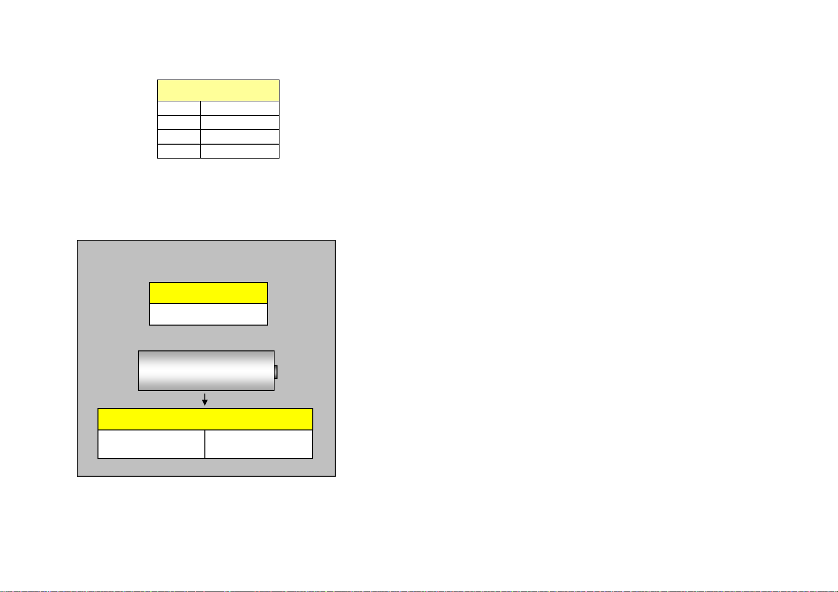
Replacement Battery:
Supplied battery
P/No. ERS-ZOD-1312007
3.6V x 2.4Ah AA
Lithium Thionyl Chloride
-
non - rechargeable cell
+
Suitable batteries also available from :
R S Components
Stock No. 596-602
Farnell Components
Order code 206-532
Table of contents 1
1. INTRODUCTION
1.1 Model number designation 2
1.2 Specifications 3
1.3 Overview 4
1.4 LCD displays 4
2. OPERATION
2.1 Batch Set 5
2.2 Batch RUN 5
2.3 Batch STOP 5
2.4 Batch Total 5
2.5 Accumulative total 5
2.6 Total Number of Batches ( TNB ) 5
2.7 Keypad function matrix 5
3. INSTALLATION
3.1 Mounting - integral mount - wall mount 6
- pipe mount – panel mount 7
3.2 Flowmeter connections - unpowered sensors 8
- powered sensors 9
3.3 Wiring connections - external powering 10
- remote switches 10
- wiring requirements 10
- single stage control 10
- two stage control 11
- relay control logic 11
- status & relay connections 16 & 17
4. PROGRAM PARAMETERS
4.1 PIN number protection 12
4.2 Resetting accumulative total 12
4.3 Engineering units 12
4.4 K-factor (scale factor) 12
4.5 Decimal points 12
4.6 Count direction 12
4.7 Start delay & Pre-stop 12
4.8 Automatic overrun compensation ( AOC ) 13
4.9 Missing pulse detection - no flow alarm output 13
4.10 Batch limiting 13
4.11 Controller network ID number 13
5. PROGRAMMING FLOW CHART 14
6. BATCH OPERATING PROCEDURE 15
7. SECONDARY I/O
7.1 Batch status output 16
7.2 No flow alarm output 16
7.3 Run inhibit input 16
7.4 Solid state output logics ( NPN selection ) 17
7.5 Solid state output logics ( PNP selection ) 17
8. BATCH CONTROLLER NETWORKING 18 & 19
9. REFERENCE INFORMATION
9.1 Program detail record 20
9.2 Error messages 20
9.3 Back up PIN number 20
10. ALPHABETICAL INDEX 21
Page 12

2 Introduction
1.1 Model number designation
Order Details (E
Model Housing Type
ZOD-B1 KM¹⁾ = integral mount
xample: ZOD-B1KS1F300)
KS = universal mount
(standard)
PP = panel mount
(IP20)
¹⁾order only when retrofitting a pulse meter
²⁾only possible with ZOD-B1PP...
Electrical
connection/
Cable gland
=
1
3 x cable entry
M20
2 =
3 x cable entry
1/2" NPT
0²⁾ =
screw terminal
Supply Voltage Options
F3 = 8…24 VDC,
Battery
F1²⁾ = 110 VAC,
8…24 VDC 0 = without
R = 2 x
Relay
F0²⁾ = 220 VA
8…24 VDC
C,
(for ZODB1K)
Mechanical
protection
0 =
without
S²⁾ = silicone
bezel boot
1.2 Specifications
Display : 8 digit alpha numeric LCD characters 9mm
Functions : Batch total, Accumulated total & Total number of batches (TNB).
Configuration : Flow chart entry of data with scrolling English text prompts. User
Signal Input : Universal pulse/frequency input compatible with Reed switch,
Power requirement : Regulated 12~24Vdc x 50mA (add switched current).
Battery : 3.6Vdc lithium battery annunciates a power loss & preserves
Control outputs : Two independent NPN open collectors, 1A dc resistive load max.
Introduction 3
( 0.35 ”) high with
second line sub script text. 8 digits totalising, 3 programmable
decimal points, 5 digits for Total number of batches.
selectable 4 digit PIN number set-up protection. Programmable
decimal points and K-factors. All programmed data and batch
status are E
2
PROM protected in the event of a power failure.
Hall effect, Namur proximity detectors, Pulse wire, voltage,
current & Coil (15mV P-P min). Max. input frequency 10Khz.
batch settings & progress at time of power loss.
May be link configured for PNP to drive compatible logic circuits.
Part No.
1522001 stainless steel wall mount kit
1522002 stainless steel 2" pipe mount kit
1522011 DOM series cooling fin kit for flowmeters with integral instruments
1522005 DOR & Turbine stem adaptor - metric ( M16 to M20 )
1522006 DOR & Turbine stem adaptor - USA ( M16 to 1/2" NPT )
1323006 DOR-42 stem ( 100mm effective height, threaded M16 male )
1323011 DOR-52 stem ( 350mm effective height, threaded M16 male )
1412063
ACCESSORIES FOR ABOVE SERIES: Model: ERS-ZOD-...
Relay contol output board with two SPCO relays
Alarm / pulse output : NPN-PNP solid state alarm or non-scaleable pulse output @
terminal 7, ( 5000hz max.), 1A maximum drive capability.
Batch status output : NPN open collector, 0.1A dc resistive load max.
(page 16).
K-factor range : Eg. Pulses/litre, gallon, lb etc. Programmable range is 0.001~
9999999.999 with a floating decimal point during K-factor entry.
Engineering units : Selectable Ltr, gal, m3, kgs, lbs (maximum 8 digits of batch).
Count direction : Count UP or count DOWN selectable at program level.
Automatic overrun : AOC enabled-disabled selection at programming level (
page 13).
compensation
Batch limiting : Batch size limits can be set at programming level
(page 13).
Run inhibit input : Run key can be inhibited from an external source (page 16).
Network I/O : A two wire loop system can link up to 9 individual batch
controllers with one common flowmeter to provide an economical
multi source/dispense interlocked batching system (page 18) .
Physical : A) IP66 / 67 high impact glass reinforced Polyamide enclosure.
B) 3 x M20 or ½” NPT female conduit entries.
C) 125mm diameter (5”) x 61mm deep (2.5”) x 400g (0.9lb).
D) Temperature range from -20ºC to +80ºC ( -4ºF to +176ºF).
Page 13
4 Introduction
A
p
A
1.3 Overview
The ZOD-B1 is a dc powered high speed batch controller specifically designed for liquid
batching using a flowmeter with a pulse or frequency output.
ZOD-B1 is push button programmable with PIN protection and an internal battery is provided
allowing pre-programming without applying power. The large LCD provides batch quantity in
selected engineering units, batch status and has scrolling English prompts to make
programming easy.
Two independent output relays, the second with programmable start delay and pre-stop,
enable pump and valve control or 2 stage flow phasing at the start and end of each batch.
Precise batching is aided by Automatic Overrun Compensation which, when enabled,
automatically manages variations in system time lags which could otherwise lead to
discrepancies in dispensed quantity.
Safety features includes for an alarm output and automatic cessation of batching if no flow
input is detected and programmable batch limiting protects against setting an oversize batch
quantity. Scrolling messages on the LCD annunciate any alarm fault conditions.
Control features include batch count up or down, remote operational switch interface, run
inhibit interlock and batch status output. The ZOD-B1 is capable of networking with up to 9
batch controllers using one common flowmeter.
Operation 5
2. OPERATION
2.1 Batch set : Pressing the Batch set key allows the user to enter a batch value by
using the arrowed keys to select the appropriate digits and change their value. Pressing
Batch set again enters & confirms that the new batch value has been entered.
2.2 Run : Press RESET then RUN to start the batch. If there are no interruptions the
batch controller will automatically stop the batch once the batch value has been reached.
2.3 Stop : Pressing the STOP key at any time during the batch will cause the batcher to
go into a “PAUSED ” state and the output relays will be turned off. At this point the user can
resume batching by pressing the RUN key or abort the batch by pressing the RESET key.
2.4 Batch Total : The batch value is displayed in all normal operational modes.
2.5 Accumulative Total : Accumulative total can be reset in the program mode.
The accumulative total is displayed momentarily by pressing the ACCUM TOTAL key.
2.6 TNB display ( Total number of batches ) : ZOD-B1 will accumulate the total number of
individual completed batches. Reset of TNB is simultaneous with the resetting of the
Accumulative total in program mode. To view the TNB value simultaneously press & hold the
two top right hand keys ( Prog. & Accum Tot).
Environments
The ZOD-B1 is designed to suit harsh indoor and outdoor industrial environments & conforms
to EMC directives. The housing is weatherproof to IP66/67 (Nema 4X) standards, UV
resistant, robust glass re-enforced plastic with stainless steel screws & FKM O-ring seals.
ZOD-B1 can be mounted on a variety of flowmeters or as a stand alone instrument for wall,
surface, pipe or panel mount. Various mounting kits are available.
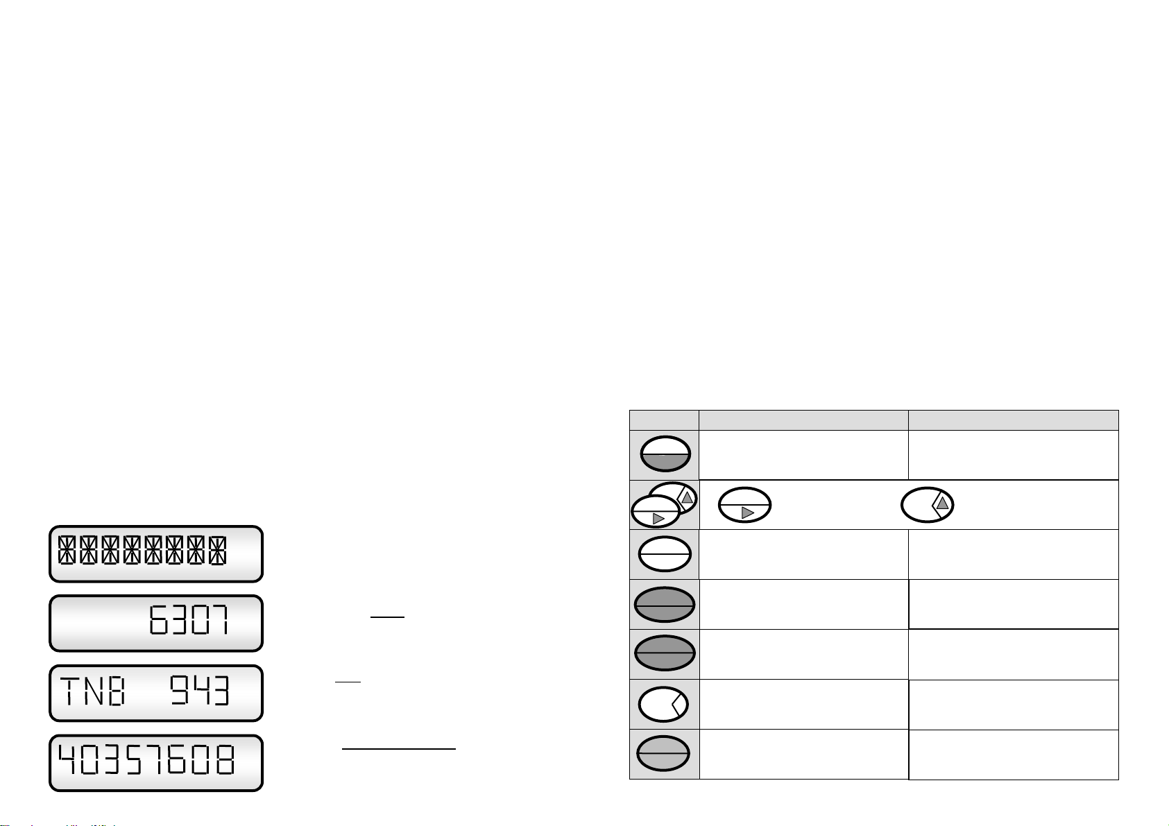
1.4 LCD displays
RUN ACCUM. TOTAL STOP BAT LOW HIGH RATE
Ltr
gal
m3
lbs
kgs
Ltr
Full LCD display test feature illuminates all
display segments and script text displays for 5
seconds when entering the program mode.
Up to 8 digits of Batch quantity programmable
for up to 3 decimal places. English prompts
RUN LOW HIGH
clearly show the status of the batch.
n 5 digit TNB display shows the Total
number of batches dispensed since last reset
TOTAL
gal
ACCUM. TOTAL
( reset of TNB and Accumulative Total is only
ossible whilst in the program mode ).
The 8 digit
ccumulative Total display can be
programmed for up to 3 decimal places. Reset
is only possible when in the program mode
which can be PIN protected for security.
2.7 Keypad functions :
KEY FUNCTION IN OPERATING MODE FUNCTION IN PROGRAM MODE
BATCH SET
RUN
RESET
ACCUM
TOTAL
PROGRAM
1) Enters & Exits the batch set mode.
2) May be pressed during batching to show
batch pre-set value, this action will not
interfere with the batch process.
Selects the digit to be Increments the selected digit
Indexed ( digit will flash ) ( selected digit will be flashing )
1) Starts a batch
2) Resumes a batch if paused
Pauses a batch during batching
1. Resets the batch to the last pre-set value.
2. Resets individual digits to zero when
in the BATCH SET
mode
.
1) Displays Unit ID number followed by the
Accumulative Total as the key is held.
2) Displays total number of batches ( press
Accum. Total & Prog. keys at the same time)
Pressing PROGRAM & ACCUM TOTAL keys
displays the Total Number of Batches ( TNB )
No function
No function
Pressing PROG & STOP keys for 5 sec.
gives entry to the program mode
No function
No function
1) Pressing PROGRAM & STOP keys for 5
seconds gives entry to the program mode.
2) Steps you through the program ladder.
3) Holding for 3 secs. fast tracks to end prog.
Page 14
6 Installation
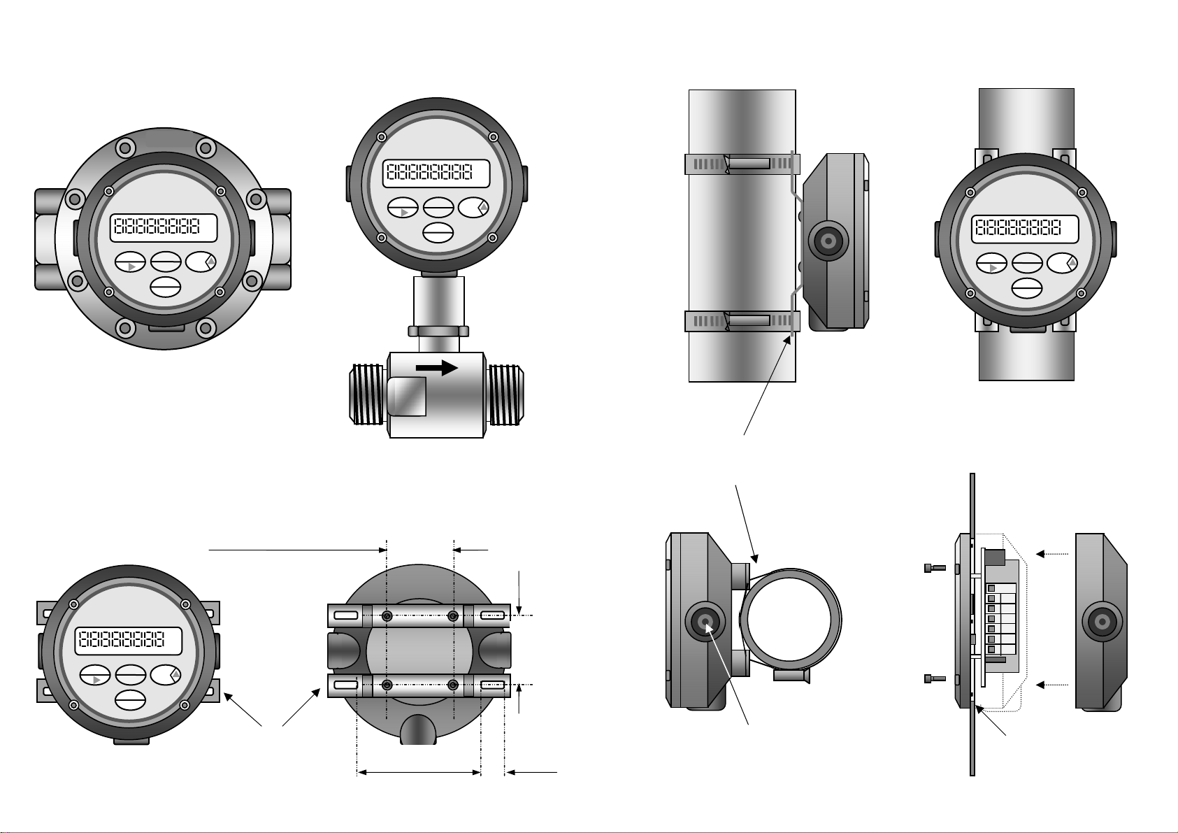
3.1 Mounting
RATE TOTALISER
RUN ACCUM. TOTAL STOP BAT LOW HIGH
RESET
RUN ACCUM. TOTAL STOP BAT LOW HIGH
RUN
BATCH
ACCUM
TOTAL
PROG
STOP
RESET
gal
PROGRAM
ACCUM
TOTAL
ENTER
RATE
TOTAL
Wall mount using optional
bracket set
gal
Integral meter
mounts
Surface mount footprint
(use 4 screws supplied )
( P/No. AWM )
RUN ACCUM. TOTAL STOP BAT LOW HIGH
RUN
BATCH
ACCUM
TOTAL
PROG
STOP
RESET
96 mm ( 3.8 ” )
gal
42.6 mm
( 1.67 ” )
18 mm
( 0.7 ” )
Installation 7
3.1 Mounting
RUN ACCUM. TOTAL STOP BAT LOW HIGH
RUN
BATCH
PROG
STOP
RESET
ACCUM
TOTAL
gal
* Vertical pipe mount
* order Pipe mount kit P/No. APM
comprising two brackets,
screws and worm drive clamps.
Panel mount
* Horizontal
pipe mount
Conduit entries have an integral
moulded seal, to remove break
seal out using suitable lever
( eg. screwdriver or rod )
Cut a 106.5mm (4.2 ”)
diameter hole in panel
Page 15
8 Installation
t
t
t
_
_
t
t
_
t
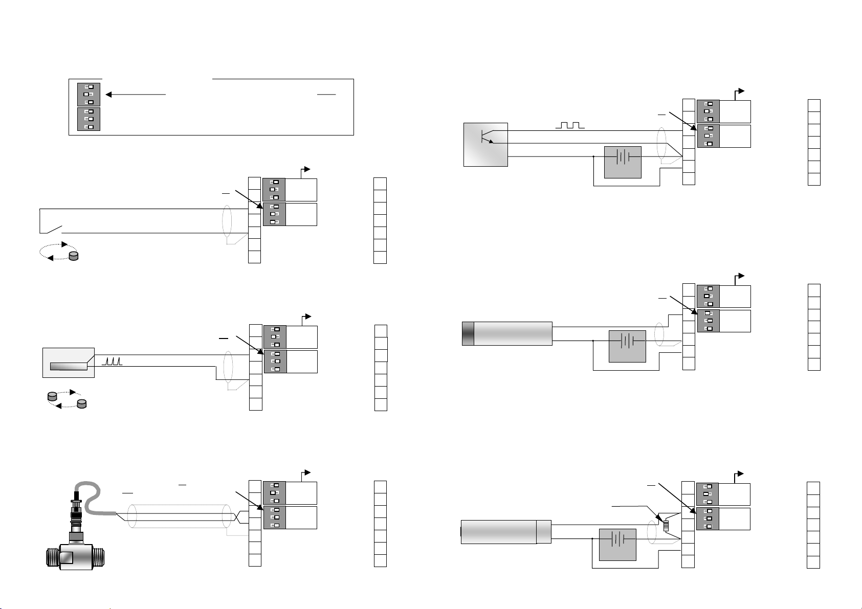
3.2 Flowmeter connections ( un powered sensors )
Flow input switch functions
3
O
2
N
1
3
Flow
O
2
Input
N
1
Switch 1 : ON engages 0.01µf capacitor to suppress reed switch bounce
Switch 2 : ON engages 1 meg Ω pull up resister
Switch 3 : ON engages 820Ω pull down resister
Factory set network default settings, do not change
1. Reed switch ( 200hz max.)
Flow DIP switches 1 & 2 are on
Ground screen at -0V (5)
3
1
O
2
N
2
1
3
3
O
2
N
4
1
-0V (ground)
5
+8~24Vdc in
6
Pulse output
7
Factory set, do not change
Network
loop
Flow
Input A
Relay 2 (high)
Relay 1 (low)
Batch status
Not used
Not used
Inhibit inpu
-0V (ground)
14
13
12
11
10
9
8
2. Voltage Pulse ( & pulse wires )
1.1 ~ 30 Vdc
+
_
N
S
All flow DIP swithes off
Ground screen at -0V (5)
3
1
O
2
N
2
1
3
3
O
2
N
4
1
-0V (ground)
5
+8~24Vdc in
6
Pulse output
7
Factory set, do not change
Network
loop
Flow
Input A
Relay 2 (high)
Relay 1 (low)
Batch status
Not used
Not used
Inhibit inpu
-0V (ground)
14
13
12
11
10
9
8
3. Coil ( Turbine & paddle style flowmeters )
All flow DIP switches off (position switch 1
if unit is effected by line noise)
ON
use twisted pairs
3
1
O
2
N
2
1
3
3
O
2
N
4
1
5
-0V (ground)
+8~24Vdc in
6
Pulse output
7
Factory set, do not change
Network
loop
Flow
Input A
Relay 2 (high)
Relay 1 (low)
Batch status
Not used
Not used
Inhibit inpu
-0V (ground)
14
13
12
11
10
9
8
Installation 9
3.2 Flowmeter connections ( powered sensors )
4. Hall Effect ( open collector )
Hall effect
+ Signal out
- 0V ground
Vdc supply
Flow input DIP SW2 is on
+
Reg. Vdc
3
1
O
2
N
2
1
3
3
O
2
N
4
1
-0V (ground)
5
+8~24Vdc in
6
Pulse output
7
Factory set, do not change
Network
loop
Flow
Input A
Relay 2 (high)
Relay 1 (low)
Batch status
Inhibit inpu
-0V (ground)
5. Namur ( inductive proximity switch )
intrinsically safe NAMUR proximities
NAMUR
Inductive Proximity
NOTE : Limit supply to 8.5Vdc
through an approved barrier for
-
+
Flow input DIP SW3 is on
+
Reg. Vdc
3
1
O
2
N
2
1
3
3
O
2
N
4
1
-0V (ground)
5
+8~24Vdc in
6
Pulse output
7
Factory set, do not change
Network
loop
Flow
Input A
Relay 2 (high)
Relay 1 (low)
Batch status
Inhibit inpu
-0V (ground)
6. Current modulated pulse
( 4mA to 20mA pulse amplitude )
Coil with pre-amp
current modulated
NOTE : Position a 100Ω, ¼W
Resistor across terminals 3 & 5
Flow input DIP switches off
-
B
A
+
+
Reg.Vdc
3
1
O
2
N
2
1
3
3
O
2
N
4
1
-0V (ground)
5
+8~24Vdc in
6
Pulse output
7
Factory set, do not change
Network
loop
Flow
Input A
Relay 2 (high)
Relay 1 (low)
-0V (ground)
Batch status
Inhibit inpu
Not used
Not used
Not used
Not used
Not used
Not used
14
13
12
11
10
9
8
14
13
12
11
10
9
8
14
13
12
11
10
9
8
Page 16
10 Installation
_
w
_
w
_
_
_
V
w
3.3 Wiring connections
Powering & Remote switches
+
Reg.Vdc
1
2
3
4
-0V (ground)
5
+8~24Vdc in
6
No flow alarm
7
( remote keys )
Network loop
Flow
Input
Relay 2 high
Relay 1 lo
Batch status
not used
not used
Run inhibit
-0V (ground)
Remote keys
15 16 17 18 19
use momentary contact
14
13
12
11
10
9
8
remote switches only
STOP
TOTAL
SET
RUN
15 16 17 18 19
Wiring requirements : Use multi-core screened twisted pair instrument cable (0.25~0.5mm
electrical connection between the ZOD-B1 and any flowmeter or remote switch input. The screen needs to be
grounded at -0V (terminal 8), this is to protect the transmitted signal from mutual inductive interference.
Instrument cabling should not be run in a common conduit or parallel with power or high inductive load cables.
Power surges & power line frequencies may induce erroneous noise transients onto the signal. Run instrument
cables in a separate conduit or with other instrument cables.
2
) for
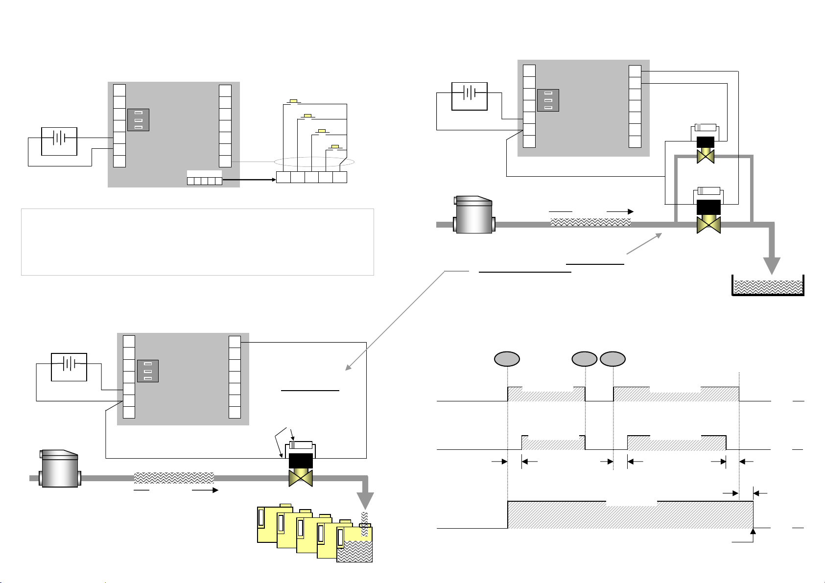
Single Stage Control
( use relay 1 or 2, relay 2 has pre-stop programming capability )
+
Reg.Vdc
Network
1
2
3
4
5
6
7
Flow
Input
-0V (ground)
+8~24Vdc in
No flow alarm
Relay 2 high
Relay 1 lo
Batch status
not used
not used
Run inhibit
-0V (ground)
14
13
12
11
10
9
8
IMPORTANT
Fix 1N4004 electrical surge
suppression diode supplied
across solenoid valve coil
( band to + side )
Flow
meter
Flow
+
1N4004
Installation 11
Two Stage Control
( using relays 1 & 2 )
+
Reg.Vdc
Network
1
2
3
4
-0V (ground)
5
+8~24Vdc in
6
No flow alarm
7
Flow
Input
Relay 2 high
Relay 1 lo
Batch status
not used
not used
Run inhibit
-0V (ground)
14
13
12
11
10
9
8
+
1N4004
1
_
1N4004
V2
Flow
meter
Flow
+
See notation on 1N4004 diode. When the solenoid valve coil is de-energized
it generates its own voltage sending a “surge spike” through the circuit.
Depending on the coil size and the number of amp turns it contains, this
generated voltage can be very high. Installing the diode will suppress this
“spike” and protect sensitive components of the electronic instrument.
IMPORTANT
Relay Control Logic
Batch
complete
Relay 1 LOW FLOW
ENERGISED
Relay 2 HIGH FLOW
Start delay
Start delay
Batch & network
status ( NPN ) output
ENERGISED
Batch & network status (end of batch)
(occurs 1~4 seconds after relay 1 is off)
ENERGISED
ENERGISED ENERGISED
OFF
OFF
Pre-stop
1~4 sec.
OFF
Page 17

12 Programming
4. PROGRAM PARAMETERS
4.1 PIN No. Program Protection
Any user defined PIN number other than 0000 will engage the program protection feature,
failure to input the correct PIN number will deny the ability to change any of the program
parameters but will allow the user to step through and view the existing program parameters.
Only one PIN number may be set but this can be changed at any time after gaining access
through PIN entry. A second back up PIN number is installed at the factory should the
programmed PIN be lost or forgotten. ( refer bottom of page 19 for the back up PIN No. )
4.2 Resetting Accumulated Total & Total Number of Batches ( TNB )
Resetting the Accumulated Total & Total Number of Batches (TNB) is done at “RESET
ACCUMULATIVE TOTALS ” in the program mode. Both Accumulated Total & TNB are reset
if you select YES
at this program level.
4.3 Engineering Units ( refer clause 1.4 )
Select from available Engineering units to right of the display. No engineering units denote
NIL set allowing the user to set up the instrument with other units of measure which are not
available on the ZOD-B1 LCD display.
4.4 K-factor ( scale factor )
Enter K-factor starting with the most significant number, up to 7 prime numbers & 3 decimal
numbers can be entered. Trailing decimal numbers move into view as digits to the right are
progressively selected, any significant digits which may move from view remain functional.
4.5 Decimal Points
Up to three decimals points can be selected for Batch Total or Accumulative Total.
4.6 Count Direction
B1 can be programmed to count DOWN from a preset quantity or UP from zero.
Overruns in the count down mode will show with a minus sign in front of the overrun value.
4.7 Start Delay & Pre-Stop
Relay 2 can be programmed to turn on a time period after the run signal is given then turn off
again a preset number of litres, gallons etc. before the end of the batch. These operational
features provide greater control over the dynamics of the batching process through soft start
and/or soft stop or phasing of the control valves and/or pump control.
The Start Delay can be set from 0 seconds ( no delay ) to 999 seconds. The pre-stop range
is 0 (no pre-stop) to 999 units of measure ( litres or gallons etc.).
Programming 13
4.8 Automatic Overrun Compensation ( AOC )
Most batching applications will have an inherent end of batch overrun due mainly to the
response time of the process valve. Overrun can be compensated by closing the valve
slightly before the batch value is reached so that the exact batch value is achieved by the
time that the system comes to rest.
ZOD-B1 has an Automatic Overrun Compensation feature which when enabled will assess
the degree of overrun on previous batches and automatically alters the close timing of the
process valve so that the exact batch value is reached. This feature should not be enabled
on batch processes which are subject to erratic or inconsistent flow conditions.
4.9 Missing Pulse Detection
When a value other than 00 seconds is set at Time Out ( T / OUT ) in the program mode,
ZOD-B1 will monitor for loss of flowmeter input signal at all times when either of the control
relays 1 & 2 are energised. If no pulses are received within the time out period ( 0~99 sec. )
the controller will de-energise both control relays and scroll a “NO INPUT” message across
the LCD display, at the same time it will turn on the “no flow alarm” output at terminal 7, (see
page 17 for flow alarm connection detail).
At “NO INPUT ” the user must acknowledge the alarm condition by pressing the STOP key
once, the operator then has the option of continuing the batch by pressing the RUN key or
aborting the batch by pressing the RESET key which will return the controller to the original
batch set value.
4.10 Batch Limit
To avoid entering excessive batch quantities, a maximum batch limit can be set at the
program level. ZOD-B1 will not accept a batch value which exceeds the batch limit, on
rejecting an excessive batch value the controller will scroll the message “BATCH VALUE
EXCEEDS BATCH LIMIT” and default to the batch limit on entry (batch set).
4.11 Controller networking ID number
Each controller can be given a networking ID number in the range of 1~9. Allocating an ID
number other than 0 is only necessary when a number of controllers are to be networked
together for interlocking purposes
( see page 18 for Controller Networking ). Setting the ID
number to zero inhibits this function.
Note : The instrument defaults out of the program mode if no program entries are made
after 4 minutes.
Page 18
14 Programming
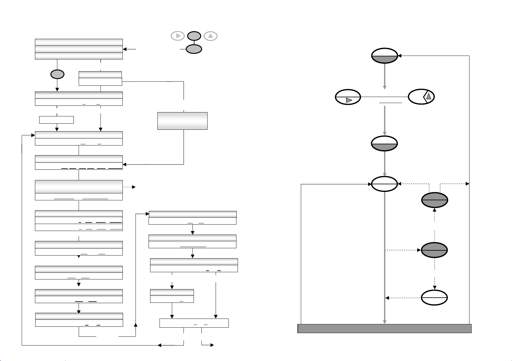
5. PROGRAMMING FLOW CHART
press Prog. key
to step through
program levels
ENG UNIT Ltr gal m3 Ibs kgs (none)
DPt TOTAL 0 0.0 0.00 0.000
DPt ACCUM TOTAL 0 0.0 0.00 0.000
V3.1 HOLD 3 2 1
TESTING DISPLAY 88888888
PROGRAM MODE ENTERED
if PIN protected
PROG
CHANGE PIN No. Y / N
NU PIN Y ~ N
YES NO
PIN _ _ _ _
RESET ACCUM TOTALS Y / N
RESET Y ~ N
SET ENGINEERING UNITS
ENTER NUMBER PULSES PER
Ltr m3 kg gal Ib (unit)
K 0000.001 ~ 999999.999
SET DECIMAL POINTS
SET COUNT DIRECTION
COUNT DN ~ UP
START DELAY - RELAY 2
DELAY 000 ~ 999 seconds
PRE STOP VALUE - RELAY 2
PRE 000 ~ 999
AUTOMATIC OVERRUN COMPENSATION
A/COMP Y ~ N
ENTER PIN
PIN _ _ _ _
continued
PROG
hold Program & Stop
keys for 5 secs to
enter the program
PIN No. is entered
INVALID PIN VIEW
EXISTING PROGRAM
DETAILS ONLY
K-factor (scale factor) is the number of
pulses per unit volume or unit mass
eg: 20.465 pulses / litre, gallon, kg etc.
SET MISSING PULSE TIME OUT
T / OUT 00 ~ 99 seconds
SET BATCH LIMIT
NETWORK OPERATION
N / WORK Y ~ N
YES
SET UNIT ID No.
ID No. X
STOP
if incorrect
XXXXXXXX
See page 13.
END Y ~ N
NO
YES
NO
Exit program
mode
Operating 15
6. BATCH OPERATING PROCEDURE
TO REPEAT
BATCH
B A T C H E N D
BATCH SET
ENTER BATCH
QTY. XXXXXXXX
BATCH SET
RUN
TO
PAUSE
TO CHANGE
TO ABORT
TO RESUME
BATCH
RESET
STOP
RUN
Page 19
16 Secondary I/O
0
0
(
)
(
)
0
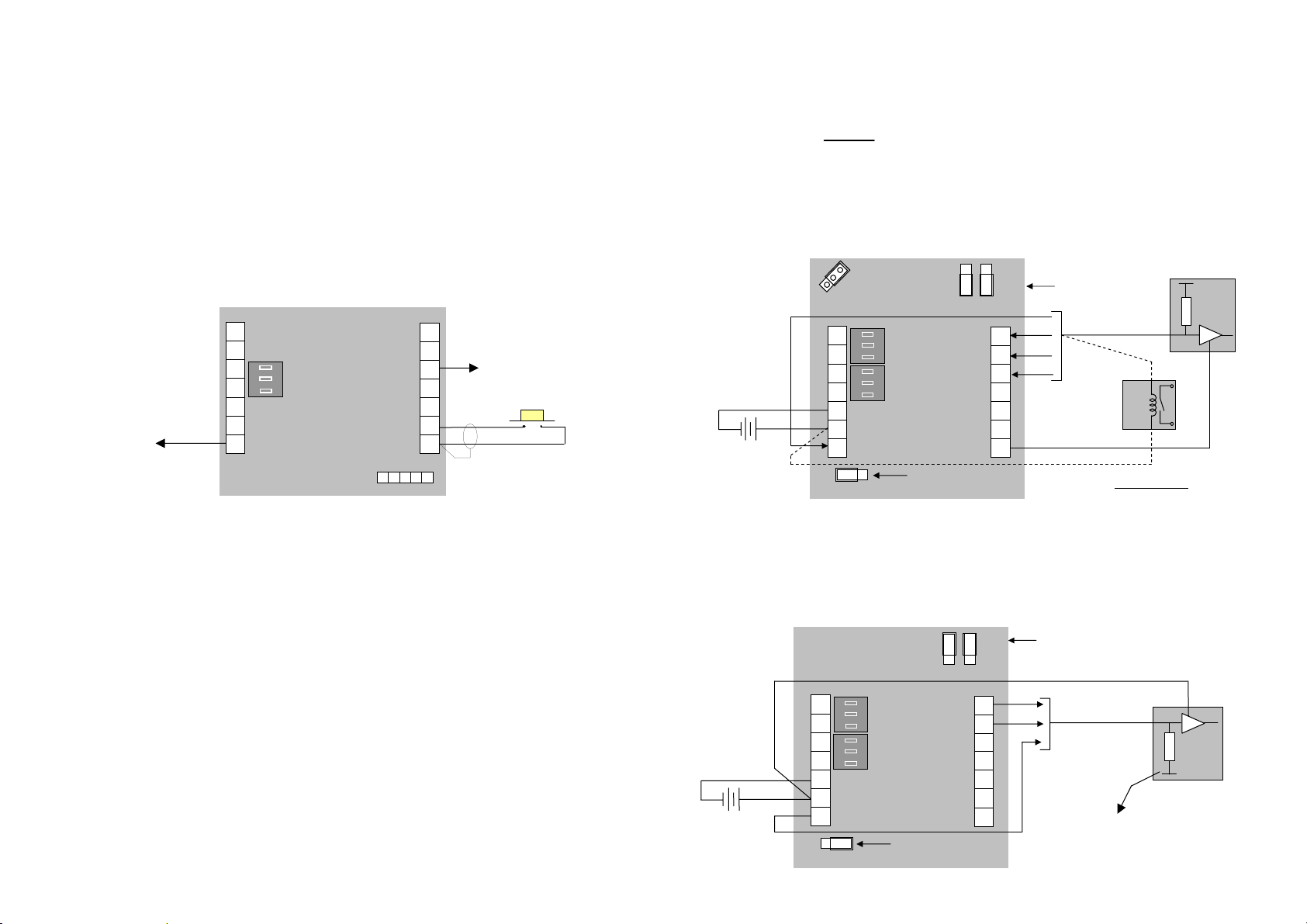
7. SECONDARY I/O
7.1 Batch Status Output
A solid state NPN output signal is switched on at terminal 12 when a batch is started, the
signal remains on until the batch cycle is completely finished or the batch is stopped and
aborted using the STOP & RESET keys.
The output is used to notify other control equipment when ZOD-B1 is in operation or is
paused (by pressing STOP) or inhibited through an input at terminal 9 (RUN inhibit), the
signal remains on under all three conditions. The signal can also be used to inhibit (lock out)
other equipment whilst the controller is in use.
1
No flow alarm
(refer 7.4 & 7.5)
Network
2
3
Flow
input
4
5
-0V (ground)
+8~24Vdc in
6
7
Alarm output
High flow-relay 2
Low flow-relay 1
Batch status
Run Inhibit
-0V (ground)
14
13
12
11
10
Remote keys
15 16 17 18 19
Batch status
(refer 7.4)
9
8
Run inhibit
input
( closed = inhibit RUN )
7.2 Alarm Output
An NPN/PNP selectable solid state output signal (terminal 7) is activated when the missing
pulse detection feature detects a no flow condition (refer 4.9). NPN/PNP selection is to be in
accordance with the connection options on the following page (17).
7.3 Run Inhibit Input
The RUN inhibit feature enables ZOD-B1 to interlock with other devices within the system or
process when ZOD-B1 is in use.
When a contact is made across the Run inhibit input at terminal 9, a batch cannot be started
and at the same time an “ENGAGED “ prompt will show on the LCD display. If the inhibit
contact is made whilst a batch is running the batch will be paused. When the run function is
inhibited it is still possible to enter a new batch quantity or review the accumulated totals but
it will not allow the operator to RUN or re-start the batch until the inhibit input is released.
An example of this feature in practice is where a batch should not be allowed to RUN whilst a
valve at another location is open.
Solid state output logics 17
7.4 Current Sinking outputs ( NPN )
Current sinking derives its name from the fact that it “sinks current from a load”. When activated the
current flows from the load into the appropriate output ( terminals 7, 12, 13 & 14 ). NPN is the factory
default configuration for the outputs. Refer to pages 10 & 11 for wiring control outputs.
Driving a logic input The output voltage pulse is typically the internal voltage of the load.
The load would normally have an internal pull up resistor on its input as shown.
Driving a coil - - - - - - - The NPN style of output is to be used when driving a coil. The coil load is
obtained by dividing the coil voltage by coil impediance ( Ω ), is expressed in amps & is not to exceed
100mA at terminals 7 & 12 or 1A at terminals 13 & 14. The coil voltage is connected across & must
match the ZOD-B1 supply voltage & the appropriate output ( terminals 7, 12, 13 & 14 ).
- +
SPO (no flow alarm)
REP repeater pulse
7A
1
2
3
4
-0V (ground)
5
+8~24Vdc in
6
Alarm output
7
7B
0 0 0
PNPNPN
High flow relay 2
Low flow relay 1
Set jumper
7.5 Current Sourcing outputs ( PNP )
Current sourcing gets its name from the fact that it “sources current to a load”. When activated the
current flows from the output (7,13 & 14) into the load. When wired as below the output voltage pulse
is the supply voltage of the load. The load would normally have an internal pull down resistor on its
input as shown.
0
0
13
Batch status
NPN
-0V (ground)
to NPN
0
0
14
13
0
PNP
0
14
14
13
12
11
10
9
8
0
PNP
0
NPN
Set jumper(s)
NPN
to NPN
coil
For solenoid valve coils fix a 1N4004 electrical surge
suppression diode across the coil (refer page 10)
Set jumper(s)
to PNP
IMPORTANT
OR
logic
+
input
load
_
- +
1
2
3
4
5
-0V (ground)
+8~24Vdc in
6
Alarm output
7
0 0 07B
PNP
NPN
High flow relay 2
Low flow relay 1
PNP
-0V (ground)
Set jumper
to PNP
14
13
12
11
10
+
logic
input
_
load
9
8
Do not tie 0 volts of the
logic input to 0 volts of
the ZOD-B1 when wired
in PNP configuration
Page 20
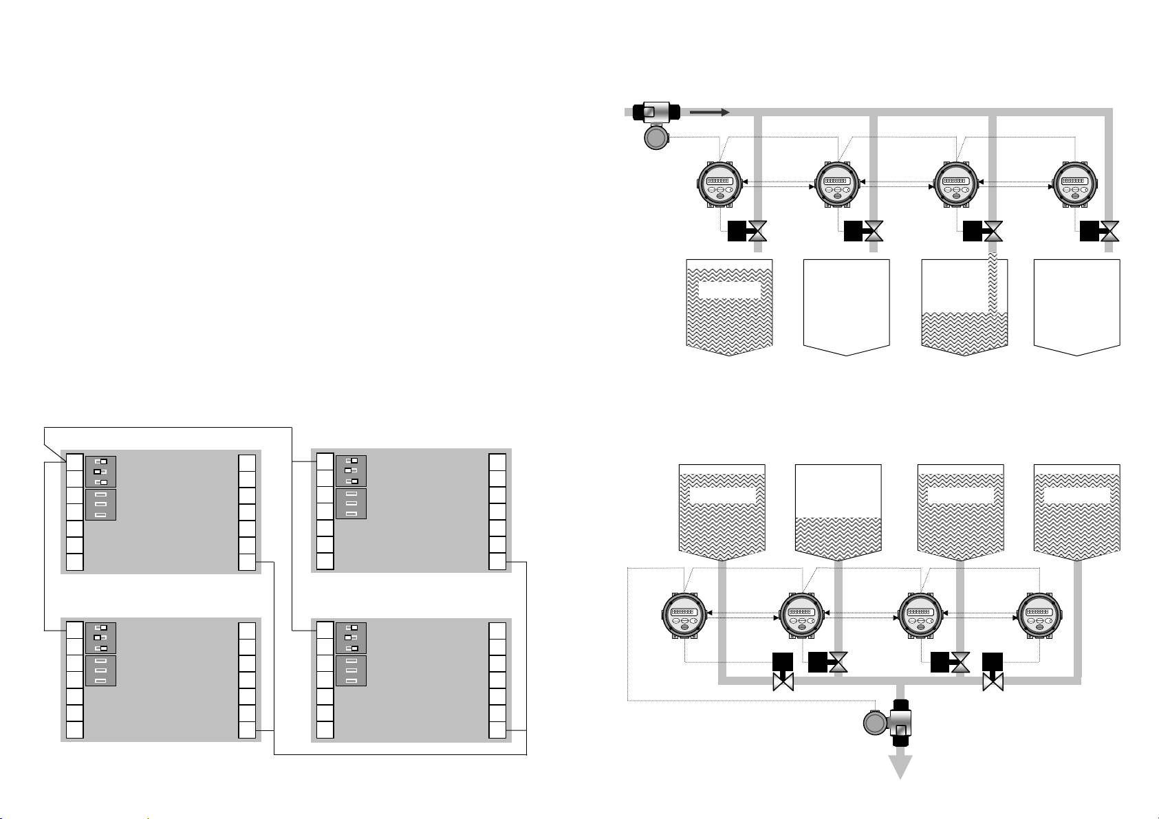
18 Networking
V1V
8. CONTROLLER NETWORKING
ZOD-B1 has a unique networking feature which allows up to 9 individual batch controllers to
be networked together with each being connected to one common flowmeter (see opposite).
Typical applications are where one liquid is being dispensed to a number of individual outlets
or a number of different liquids are to be batched via one common flowmeter. In either
application each batch controller is wired to the same flowmeter but controls its own process
control valve.
Networking takes place when any one controller is started, at this point the flowmeter input
(count) is restricted to the controller in use, all other controllers will not count and their start
function will be inhibited and an “ENGAGED” will scroll across the LCD display showing the
ID number of the controller in use.
Batch entries can be made whilst individual batch controllers are inhibited (locked out) but
they cannot be started until the controller in operation has completed its batch cycle.
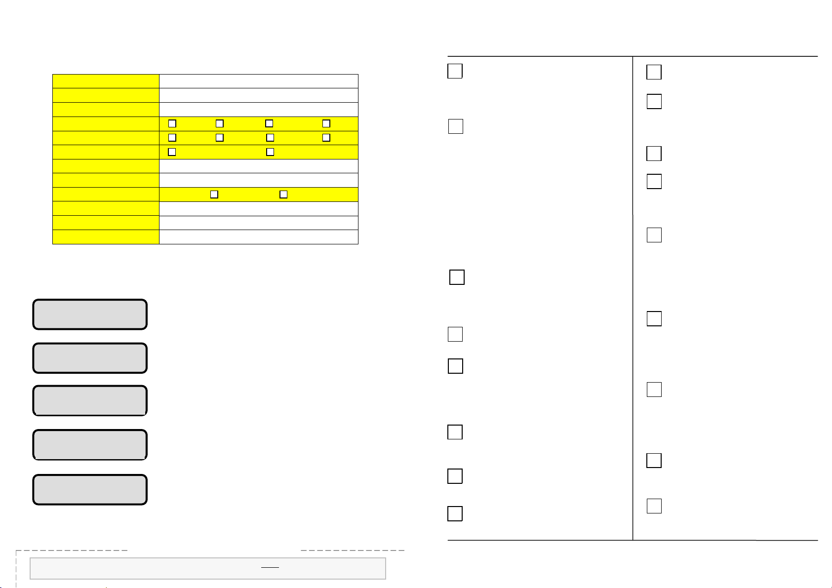
For the network feature to work the network DIP switches must be set as shown & each
batch controller MUST be programmed with an individual ID number other than 0 (zero).
Network loop wiring
1
O
N
2
3
4
-0V (ground)
5
+8~24Vdc in
6
Alarm output
7
ZOD-B1 1
3
Network
2
DIP switch
settings
1
Flow
input DIP
switches
High relay 2
Low relay 1
Batch status
Run inhibit
-0V (ground)
14
13
12
11
10
9
8
1
O
N
2
3
4
-0V (ground)
5
+8~24Vdc in
6
Alarm output
7
ZOD-B1 3
3
Network
2
DIP switch
settings
1
Flow
input DIP
switches
High relay 2
Low relay 1
Batch status
Run inhibit
-0V (ground)
14
13
12
11
10
9
8
1
O
N
2
3
4
-0V (ground)
5
+8~24Vdc in
6
Alarm output
7
ZOD-B1 2
3
Network
2
DIP switch
settings
1
Flow
input DIP
switches
High relay 2
Low relay 1
Batch status
Run inhibit
-0V (ground)
14
13
12
11
10
9
3
Network
1
O
2
DIP switch
N
2
3
4
-0V (ground)
5
6
Alarm output
7
settings
1
Flow
input DIP
switches
+8~24Vdc in
ZOD-B1 4
High relay 2
Low relay 1
Batch status
Run inhibit
-0V (ground)
14
13
12
11
10
9
88
Flowmeter
ZOD-B1 1
Networking (continued) 19
Multi point batching
ZOD-B1 1
V1
Mix tank 1
ZOD-B1 2 ZOD-B1 3
network
loop
Valve
V2 V3 V4
Mix tank 2 Mix tank 3 Mix tank 4
Multi product batching
Product 2
V2 V3
Valves
Flowmeter
Product 3 Product 4
Product 1
ZOD-B1 2 ZOD-B1 3
network
loop
ZOD-B1 4
ZOD-B1 4
4
Page 21
Reference information 20
9. REFERENCE INFORMATION
9.1 Program detail
User selected PIN No.
K-factor (scale factor)
Decimal for batch total
Decimal for Accum. total
Count direction
Start delay on relay 2
Pre-stop value on relay 2
Automatic overrun comp.
Missing pulse time-out
Batch limit
Unit ID number ( 1~9 )
9.2 Error messages: ZOD-B1 has a series of error messages which are scrolled
across the LCD display when ever an error condition exists.
NO POWER
No power indicates that the instrument is on battery power
only and needs to be supplied with an external power source
in order to operate.
NO INPUT
No input (missing pulse detection) indicates that no pulses
were received at the controller input within the time out period
at any stage of the batch cycle. ( see clause 4.9 )
BATCH VALUE EXCEEDS
BATCH LIMIT
The new batch value will not be accepted because it
exceeds the maximum batch limit value. ( see clause 4.10 )
PRE-STOP EXCEEDS
BATCH VALUE
The new batch value will not be accepted as it is less than
the pre-stop value ( clause 4.7)
WAIT
This message will show if the RUN button is pressed whilst
the controller is in the process of assessing the degree of
overrun from the previous batch when AOC is enabled.
9.3.1 Back up PIN number ( see clause 4.1 )
Cut from manual for increased security
Your back up 4 digit PIN number is 0502
Pencil your program details here
Engineering units
K =
000. 00.0 0.00 .000
000. 00.0 0.00 .000
count DOWN count UP
seconds
AOC yes no
seconds
( 0 = inhibit network function)
10. ALPHABETICAL INDEX
Accumulative total
A
Alarm output
Automatic Overrun Comp. 13
B
Batch RUN
Batch SET
Batch STOP
Batch total
Batch limit
Batch operating procedure
Batch status
Back up PIN number
Battery
C
Controller ID number
Controller networking 18,
Count direction
Decimal points 12
D
Engineering units 3,
E
End of batch
Error messages
External DC powering
F
Flow alarm output
Flowmeter connections 8,
ID numbering
I
Inhibit input
Keypad functions
K
K-factor (scale factor) 12,
(batch status)
11, 16 & 17
16
5
5
5
13
15
16
20
4
12
20
18
13
16
14
5
13
19
12
10
Index 21
5
LCD display 4
L
Model number designation 2
M
Missing pulse detection
Mounting options 6,
Networking 18,
N
Operation 5
O
13
7
19
Overrun compensation 13
Overview
PIN number protection
P
Pre-stop
4
12
12
Programming 12, 13
Program detail record 20
Programming flow chart
14
Relay control logic
R
Remote operating keys
Resetting totals
Run inhibit input
Scale factor (K-factor) 12,
S
Single stage control
Specifications
Start delay
11
10
12
16
14
10
12
3
9
Total Number of Batches
T
Two stage control
Wiring connections 10,
5
W
Wiring requirements
5
11
11
10
Page 22

K01/1010
Manufactured and sold by:
ZOD-Z1 BATTERY TOTALISER
I N S T R U C T I O N M A N U A L
Kobold Messring GmbH
Nordring 22-24
D-65719 Hofheim
Tel.: +49(0)6192-2990
Fax: +49(0)6192-23398
Universal Mount Series
Page 23

prog
y
To review software version No’s press &
hold
ram ke
Replacement Batteries:
Factory supplied batteries :
Non I.S. battery
P/No. 1312007
3.6V x 2.4Ah AA
Lithium Thionyl Chloride
-
non - rechargeable cell
+
Suitable non I.S. batteries also available from :
R S Components
Stock No. 596-602
Farnell Components
Order code 206-532
TABLE OF CONTENTS
1. INTRODUCTION
1.1 Model number designation 2
1.2 Specifications 3
1.3 Overview 4
1.4 LCD displays 4
2. OPERATION
2.1 Resettable total 5
2.2 Accumulative total 5
2.3 Keypad function matrix 5
2.4 Battery replacement 5
2.5 Processor reset button 5
3. INSTALLATION
3.1 Mounting - integral meter mounting 6
- panel mounting 6
- wall / surface mounting 7
- pipe mounting 7
3.2 Flowmeter connections - un-powered sensors 8
- powered sensors 9
3.3 Wiring connections - Terminal designation 10
- Interface board layout 10
- Wiring practice 10
- PNP pulse output 11
4. PROGRAM PARAMETERS
4.1 PIN number protection 12
4.2 Resetting accumulative total 12
4.3 Engineering units 12
4.4 K-factor (scale factor) 12
4.5 Pulse output 12
5. PROGRAMMING FLOW CHART 13
5.1 Program detail record 14
6. TROUBLESHOOTING 14
7. Declaration of Conformance 16
8. ALPHABETICAL INDEX 17
- NPN pulse output 11
Page 1
Page 24

2 Introduction
Introduction 3
1.2 Specifications
1. INTRODUCTION
Model Housing Type Electrical connection/
ZOD-Z1...
*order only when retrofitting a pulse meter
KS = universal mount
(standard)
KM* = integral mount
Cable gland
0 = cable gland supplied
(suits 3...6 mm Ø cables)
Supply Voltage Options Mechanical
F3= 8...24 VDC, battery 0= without 0= without
protection
Display : 5 digit resettable LCD totaliser 7.5mm ( 0.3”) high with second
line 8 digit accumulative total display & text 3.6mm ( 0.15”) high.
3 programmable decimal points with both display lines.
Signal Inputs : Universal pulse-frequency input compatible with Reed switch,
Hall effect, Coil-sine (20mV P-P min.), Voltage or current pulse &
Namur proximity detectors. Maximum input frequency is 5Khz for
coils, 2.5Khz for Hall effect & current pulse inputs, 2Khz for voltage
pulse devices & 500Hz for a Namur proximity sensor.
Powering : 3.6Vdc Ultra Lithium battery or I.S. battery pack supplied, life
expectancy can be up to 7~10 years. Battery life reduces when
connected with a coil input from turbine flowmeters. The ZOD-Z1
may also be externally powered from a regulated 8~24Vdc supply
(see page 14 for special instructions regarding ghosting).
Pulse output : Scaleable or non-scaleable NPN-PNP selectable field effect output
Transistor. Non scaleable pulse is particularly suitable for preamplifying pick-off coil inputs from turbine meters ( 5Khz. Max.).
The scaleable pulse output has a fixed pulse width of 60ms and
therefore has a frequency limit of 8hz . Both pulse outputs have a
50mA maximum drive capability.
Physical : A)
IP66/67 high impact, glass reinforced Polyamide enclosure.
B) Self drill cable gland entry at base & rear of the enclosure.
C) Overall 85mm diameter x 45mm deep x 175g (0.4lb).
D) Operating temperature -20ºC ~ +80ºC ( -4ºF ~ +176ºF).
Configuration
Functions : Accumulated & Resettable totals, pre-amplifier pulse output & a
scaleable pulse output. Low battery indication.
Configuration : Flow chart entry of data with English text prompts.
User selectable 4 digit PIN number program protection.
Programmable engineering units, decimal points and K-factors.
All programmed data protected with the battery.
K-factor range : Entered as pulses / litre, gallon, lb etc. Programmable range is
0.001~9,999,999.999 with a floating decimal point during K-factor
(scale factor) entry.
Pulse output range : Entered as engineering units/pulse. Range is 0.1~9999.9
units/pulse.
Engineering units : Selectable Ltr, Gal, m3, kgs, lbs, MLtr & Mgal or no units of display.
Page 25

4 Introduction
1.3 Overview
The ZOD-Z1 series i
nstruments are specifically designed for computing & displaying totals
from flowmeters with pulse or frequency outputs. They are battery powered or can be
powered by an external 8~24Vdc regulated or I.S. certified supply.
The instrument will display Resettable Total and an Accumulated Total in engineering units as
programmed by the user. Simple PIN protected flow chart programming with English prompts
guide you through the programming routine greatly reducing the need to refer to the manual.
Special Features
Standard
: PIN Protection. Amplified non-scaled repeater or scaleable pulse output.
: NPN/PNP selectable pulse output.
Optional : Display backlighting (needs external dc power for this option to illuminate).
: Intrinsic Safety Certification to IECex scheme and ATEX directive.
Environments
The ZOD-Z1 series is designed to suit harsh indoor and outdoor industrial and marine
environments. The robust housing is weatherproof to IP676 / IP67 standards, UV resistant,
glass reinforced Polyamide with stainless steel screws & FKM O-ring seals.
Installation
Specifically engineered to be directly mounted on a variety of flowmeters, wall, surface or pipe
mounted in the field or control room. Various mounting kits are available. The instrument is
self powered using one 3.6Vdc lithium battery or I.S. battery pack, the pulse output option
requires 8~24Vdc.
Operation 5
2. OPERATION
2.1 Resettable Total
Pressing the RESET key will cause the large 5 digit total to reset to zero. The reset function is
possible at any time during counting.
2.2 Accumulative Total
There are 8 digits in the accumulative total display, these can only be reset in the program
mode or can be protected by enabling the PIN protection feature at the front end of program
mode.
2.3 Keypad functions
KEY FUNCTION IN OPERATING MODE FUNCTION IN PROGRAM MODE
Resets the 8 digit accumulative
total display to zero. Resets internal K-factor
1. Each press steps you through each level of
2. Holding for 3 seconds fast tracks to the END
Selects the digit to
will be “flashing ” indicating that it can be
(scale factor) to zero
the program chart.
of the program from any program level.
be set, the selected digit
incremented.
Increments the selected
that it is pressed.
digit each time
PROGRAM
ENTER
Resets the 5 digit resettable
total display to zero.
1. Pressing the Program & Reset keys for 5
seconds enters you into the program mode
2. Displays model & software revision No.
No function
No function
.
1.4 LCD display
The 8 digit Accumulative Total display
can be programmed for up to 3 decimal
places. Reset is only possible when in
the program mode which can be PIN
protected for security.
Full LCD display test feature illuminates all
characters and script text displays for 5
seconds when entering the program mode.
The 5 digit Total display is front panel
resettable and can be programmed for
up to 3 decimal places.
Engineering units are selected during
the initial programming routine.
Battery condition indicator shows only
when battery is low, battery life can last
up to 7~10 years.
2.4 Battery replacement
The instrument draws very little power and will run for many years* without the need to
replace the battery. A battery condition indicator on the LCD display will appear when the
battery is low, if the low battery is not replaced the programmed detail & totals will be lost.
When changing the battery a small capacitor within the instrument will maintain the
programmed detail & totals in memory for up to 10 seconds providing sufficient time for the
battery change to take place. Changing the battery whilst flow is taking place could cause loss
of the programmed detail. It is advisable to record program details prior to battery change.
* The battery can last 7~10 years depending on application & environment.
2.5 Processor reset button
Should the instrument be corrupted by an electrical hit the processor can be reset by pressing
the black re-boot button located above the red DIP switch block on the input interface board
(refer page 10). This procedure does not effect totals or programmed data.
Page 26

6
3. INSTALLATION
3.1 Mounting
Integral meter mounting
Panel mounting
Cut a 75mm ( 3”) dia. hole in
panel. Existing O-ring seals
against panel face
If using the cable gland supplied
carefully
bottom or rear of housing as shown
on housing footprint detail on page 7
drill a 12.5mm (½”) hole at
Installation 7
Surface mount footprint
42.6mm
( 1.67 ” )
If using the cable gland
supplied carefully
12.5mm (½”) hole at
the underside or from
the inside rear of
housing
Use only the 4
special length
self tapping
screws supplied
drill a
Cable diameter range
is 2.9~6.4mm (⅛~¼”)
80 mm ( 3.15 ” )
Wall - surface mount using optional bracket kit ( P/No. AWM )
18 mm
( 0.7 ” )
42.6 mm
( 1.7 ” )
Pipe mounting ( P/No. APM )
APM adaptor pipe
mount kit is suitable
for vertical or
horizontal pipes
Page 27

8 Installation
p
A
3.2 Flowmeter connections ( un-powered sensors )
Reed switch input
DIP switches
ON
1 & 3 (de-bounce)
in the ON
1 2 3
+
gnd
-
( 40 hz max.)
1 2 3
position
+Vdc
4 5 6
+∏
-gnd
Note: DIP switch 3 is to be
OFF
for reed switch input
frequencies greater than 40 hz.
Ground screen at 3
Coil input from
turbines or paddle
ON
DIP switch 1 in
the ON
( 5 Khz max.)
1 2 3
position
+∏
gnd
-
+
1 2 3
+Vdc
-gnd
4 5 6
twisted pair
Voltage pulse
input (pulse
ON
1 2 3
gnd
-
+
1 2 3
Ground screen
wire)
DIP switch 1 in
the ON
position
( 2 Khz max.)
+∏
+Vdc
4 5 6
at 3
-gnd
Screen grounded at
amphenol shroud or
terminal box and
terminal 3 at ZOD-Z1
yellow
green
N
S
Installation 9
3.2 Flowmeter connections ( powered sensors )
NOTE : Voltage not to exceed 13.4 Vdc
through an approved barrier if when using
an intrinsically safe NAMUR proximity in a
hazardous area ( EEx Ia 11C ). Typically
these proximity’s are limited to 8.2 Vdc
NAMUR
Inductive Proximity
-
+
Ground screen at 3
Namur proximity
ON
DIP switch 2 in
the ON
( 250 hz max.)
1 2 3
gnd
-
+
input
position
+Vdc
4 5 6 1 2 3
+
+∏
-gnd
8~24Vdc
external
-
power
NOTE: For an input
>800hz position a ¼
Hall
effect
watt resistor across
terminals 1 & 4,
12Vdc: 1Meg
24Vdc: 2Meg Ω
Ω
+ ∏
-0V gnd
+Vdc
Ground screen at 3
Hall effect input
( NPN open collector )
ON
DIP switch 1 in
the ON
1 2 3
gnd
-
+
+Vdc
position
+∏
4 5 61 2 3
+
-gnd
8~24Vdc
-
external
power
NOTE: Position a 100 ohm,
¼ watt resistor across
terminals 1 & 3 as shown
Modulated current
pulse input (4~20mA)
ON
1 2 3
+
1 2 3
ll DIP switches
to be in the OFF
position
gnd
-
+Vdc
4 5 6
+∏
-gnd
Coil with pre-amp
current modulated
-
B
A
+
Ground screen at 3
+
8~24Vdc
-
external
ower
Page 28

10 Installation
r
(
)
p
r
(
)
( 50
)
(
)
3.3 Wiring connections
Terminal designation
1 + I/P Flow input pulse signal
2 - Vref. Flow input ( coils & voltage type inputs )
3 gnd GND Flow input ( pulse type inputs )
4 +Vdc +Vdc External power , +8~24Vdc (see P14)
5 + ∏ O/P Output pulse ( J1 & J3 selectable )
6 -gnd GND External power
Interface board layout
Processor
reset button
Input DIP
switches
1 = 1MΩ pull up resistor
2 = 820Ω pull down resistor
3 = 0.01µf de-bounce & noise capacitor
( limits max. input freq. to 40hz)
SW5
ON
1 2 3
SW6
+
gnd
-
NPN
PNP
+Vdc
J1
0
0
0
+∏
4 5 61 2 3
I/P Vref O/P
J3
0
0
0
0
0
-gnd
J2
F/O
P/O
Battery jumper
0
battery engaged
0
0
battery isolated
0
Output jumpers
J1 NPN-PNP selection
J3 Output pulse selection:
F/O non-scaled frequency
P/O scaleable pulse
Wiring practice
Use multi-core screened twisted pair instrument cable ( 0.5mm
between the instrument and any remote flowmeter or receiving instrument. The screen needs to
be earthed to the signal ground or the receiving instrument, this is to protect the transmitted
signal from mutual inductive interference. Do not
Instrument cabling is not be run in a common conduit or parallel with power and high inductive
load carrying cables, power surges & power line frequencies may induce erroneous noise
transients onto the signal. Run instrument cables in a dedicated low energy, low voltage conduit.
earth the screen at both ends of the cable.
2
) for electrical connection
Installation 11
3.3 Wiring connections - pulse outputs
Current Sinking outputs ( NPN )
Current sinking derives its name from the fact that it “sinks current from a load”. The current flows from
the load into the appropriate output (terminal 5).
Driving a logic input The output voltage pulse is typically the internal voltage of the load.
The load would normally have an internal pull up resistor on its input.
Driving a coil - - - - - - - The NPN style of output is to be used when driving a coil. The coil load is
obtained by dividing the coil voltage by coil impediance ( Ω ), is expressed in amps & is not to exceed
0.1A. The coil voltage is connected across, & must match, the ZOD-Z1 supply voltage & the output (5).
J1
NPN
PNP
1 2 3
0
0
0
+∏
+Vdc
4 5 6
J3
0
F/O
0
P/O
0
scaleable
pulse output
-gnd
8hz max.
coil
-
+
8~24Vdc external powe
NPN output pulse
( 50mA max.)
Current Sourcing outputs ( PNP )
Current sourcing gets its name from the fact that it “sources current to a load”. The current flows from the
output (terminal 5) into the load. When wired as below the output voltage pulse is the supply voltage of
the load. The load would normally have an internal pull down resistor on its input.
+
logic
input
load
_
1 2 3
PNP output pulse
mA max.
NPN
PNP
J1
0
0
0
+∏
+Vdc
4 5 6
+
J3
0
0
0
F/O
P/O
-gnd
-
external
scaleable
pulse output
8~24Vdc
NPN
PNP
8hz max.
owe
J1
J1
0
0
0
0
0
0
J1 in the
NPN position
J3
non-scaled freq.
0
0
pulse output
0
( 5Khz max.)
+
(load)
J1 in the PNP
position
J3
non-scaled freq.
0
0
pulse output
0
( 5Khz max.)
logic
input
_
Page 29

12 Programming
O
OG
T
f
4. PROGRAM PARAMETERS
4.1 PIN No. Program Protection
The option exists to protect the programmed detail & Accum. Total with a user selected four
digit PIN No. ( 0000 represents no PIN protection ). If activated the user must input the correct
PIN No., failure to do so will deny access to change any of the program parameters or reset
the Accumulative Total but will allow the user to step through and view the program details.
Only one PIN number may be set but this can be changed at any time after gaining access
through PIN entry. A second back up PIN number is installed at the factory should the
programmed PIN be lost or forgotten. ( refer page 14 for the back up PIN No. )
4.2 Resetting Accumulated Total
Resetting the accumulated total can only be done within the program mode.
4.3 Engineering Units ( refer clause 1.4 )
Select from available Eng. units to right of the display. The ZOD-Z1 can display in engineering
units not available on the LCD display by programming to “no eng. units” and a suitable Kfactor.
4.4 K-factor (scale factor)
Enter K-factor starting with the most significant number, up to 8 prime numbers & 3 decimal
numbers can be entered. Trailing decimal numbers move into view as digits to the right are
progressively selected, any significant digits which may move from view remain functional.
4.5 Pulse output
The pulse output is NPN-PNP link selectable via jumper J1. It is also selected at jumper J3 to
act as a non-scaled pre-amplified pulse output or scaleable pulse output, maximum load is
50mA.
Non-scaled pulse output:
The un-scaled repeater pulse output represents one pulse out for each input pulse from the
primary measuring element (flowmeter). This output acts as an input signal pre-amplifier
particularly suitable for pick-up coil inputs up to 5Khz. The duty cycle of the output adopts the
duty cycle of the input. The ZOD-Z1 needs to be externally powered for this feature to operate
(see page 11).
Scaleable pulse output :
The fully scaleable pulse output is programmable as the number of litres / gallons etc. per
output pulse Eg. 0.1 litres/pulse, 10 litres/pulse, 100 gallons/pulse. Range is 0.1 ~ 9999.9
Eng. unit/pulse. The ZOD-Z1 needs to be externally powered for this feature to operate ( p11
).
The scaleable pulse output is suitable only for remote integration due to the spasmodic nature
of its output frequency, it is limited to 8hz. Should the potential incidence of this output exceed
8hz it can continue to count after flow has stopped until such time as the processor buffer has
completed integration. Most scaleable pulse output requirements are low frequency due to
down scaling and therefore not effected by the buffer count effect.
Programming 13
5. PROGRAMMING FLOW CHART
hold Program & Reset
keys for 5 seconds to
enter the program mode
Note: The ZOD-Z1 will
default out of the
program mode if no
entries are made
N
RESE
press Program key to advance
through each program level. Use
PR
arrowed keys to enter parameters
if PIN
protected
if incorrect
PIN No. is entered
view program
details only
K-factor (scale factor) is the
number of pulses per unit
volume or unit mass eg:
20.465 pulses/litre, gal, kg etc.
Important: record program details overlea
Page 30

14 Programming flow chart
5.1 Program detail record
If not powered for more than 10 seconds the programmed detail & Accumulated Total will
be lost from the processor memory, it is advisable to record your programmed detail
below. Specific instructions on changing the battery without loss of program detail are
given at clause 2.4, page 5.
User selected PIN No.
K-factor (scale factor)
Decimal for reset total
Decimal for Accum. total
Output pulse value
Pencil your program details here
Engineering units
K =
0 0.0 0.00 0.000
0 0.0 0.00 0.000
0000
litres
1.000
0.0
0.0
0001.0
Factory default settings
6. TROUBLESHOOTING
# No display.
Check position of the battery jumper J2 ( see interface board layout page 10 ) & check
battery contact connections. Replace battery.
# Display ghosting under external power.
The LCD display will “ghost” when the instrument is powered from an external 24Vdc
power supply, this is corrected by including two ¼ watt resistors (1.2K & 3.3K) on the
input power source as shown below.
24Vdc
external
power
ON
1 2 3
-
+
1 2 3
+
-
ZOD-Z1
gnd
+Vdc
+∏
-gnd
4 5 6
Troubleshooting 15
# Display shows model number at all times.
example
The instrument has not been fully programmed after power up, enter the program mode &
enter program parameters, be sure to exit the program mode before the 4 minute no data
entry time out or the instrument will revert back to model number display.
# Display ghosting under external power.
The LCD display will “ghost” when the instrument is powered from an external 24Vdc
power supply, this is corrected by including two ¼ watt resistors (1.2K & 3.3K) on the
input power source as shown below.
# Scaleable pulse output counts on after flow has stopped.
The scaled pulse output has exceeded its output limit of 8Hz. Allow the memory buffer to
catch up or increase the pulse value - number of litres etc. per pulse, (clause 4.5, p12.)
# Display shows random characters.
The instrument may have taken an electrical “hit”, press the processor reset button (p10).
Cut from manual for increased security
Your back up 4 digit PIN number is 0220
.
Page 31

16 Declaration of Conformance
7. Declaration of Conformance
We, KOBOLD Messring GmbH, Hofheim-Ts, Germany, declare under our sole
responsibility that the product:
Battery Totaliser Model: ZOD-Z1
to which this declaration relates is in conformity with the standards noted below:
Optional for Equipment intended for use in Potentially Explosive Atmospheres:
ATEX Directive 94/9/EC
EN 50014: 1997 + Amds. 1 & 2 Intrinsically Safe Electronics (I.S.) – Optional
EN 50020: 2002 Intrinsically Safe Electronics (I.S.) – Optional
EN 60529, DIN VDE 0470-1 1992-11
I.P. Ingress Protection Classifications
EN 61326-1: 2006-10
Electrical equipment for control, instrumentation technology and laboratory use – EMC
requirements (Industrial area)
EN 61010-1: 2002-08
Safety requirements for electrical equipment for measurement, control, and laboratory
use –
2008/35/EC Waste Electrical & Electronic Equipment (WEEE)
Also the following EEC guidelines are fulfilled:
2004/108EC EMC Directive
2006/95 EC Low Voltage Directive
Hofheim, 18. Oct. 2010
H. Peters M. Wenzel
General Manager Proxy
Holder
Index 17
8. ALPHABETICAL INDEX
Accumulative total 5
A
Battery condition indicator
B
Battery replacement
Battery jumper
DC power ( powering )
D
Decimal points
Displays
Engineering units
E
External DC powering
Flowmeter connections 8,
F
Input signal
I
Interface board
Installation 6 ~
Keypad functions
K
K-factor (scale factor) 12,
LCD display
L
Model number designation
M
Mounting options 6,
NPN pulse output 3,
N
Operation
4
5
10
3
12
4
12
3,
3
9
8,
9
10
11
5
14
4
2
7
O
Overview & Options
PIN number protection
P
PNP pulse output 3,
Processor reset button
Programming 12,
Program detail record
Pulse output 3,
R
Resettable total
Resetting accumulative total 5, 12
Resetting the processor 5
Scale factor (K-factor)
S
Scaleable pulse output
Specifications
Terminal designation
T
Terminal layout 10
Troubleshooting 14,
Wiring connections 8 ~ 11
W
Wiring practice
11
12
11
13
14
11
12
12
10
15
10
5
4
5
5
3
Page 32

Universal Mount Series
ZOD-Z3 FLOW RATE TOTALISER
I N S T R U C T I O N M A N U A L
Page 33

Non I.S. battery
KOBOLD P/No. 1312007
Suitable non I.S. batteries also available from :
R S Components
Stock No. 596-602
Press & hold Program key to show
instrument model & software version
Replacement Batteries:
KOBOLD supplied batteries :
Lithium Thionyl Chloride
-
non - rechargeable cell
Software version
16.12.04 V 3.2
27.04.07 V 3.3
PROG
I.S. battery
Kobold P/No. 1412028
Warning : KOBOLD
Intrinsically safe battery
assembly only is approved
for ZOD-Z3 mounted in a
hazardous area.
Farnell Components
Order code 206-532
3.6V x 2.4Ah AA
+
Page 34

TABLE OF CONTENTS
1. INTRODUCTION
1.1 Model number designation 2
1.2 Specifications 3
1.3 Overview 4
1.4 LCD displays 4
2. OPERATION
2.1 Accumulative total display 5
2.2 Resettable total display 5
2.3 Rate display 5
2.4 Low frequency cut-off 5
2.5 Inhibit total function 5
2.6 Keypad function matrix 6
3. INSTALLATION
3.1 Mounting - wall / surface mount 6
- pipe mount 7
- panel mount 7
3.2 Flowmeter connections - unpowered sensors 8
- powered sensors 9
3.3 Wiring connections - external powering 10
- 4~20mA loop powering 10
- wiring requirements 10
- pulse outputs 11
- alarm outputs 11
- remote switches 18
4. PROGRAM PARAMETERS
4.1 PIN number program protection 12
4.2 Resetting accumulative total 12
4.3 Engineering units 12
4.4 K-factor (flow input scale factor) 12
4.5 Rate conversion factor 12
4.6 Rate dampening ( see response graph page 19 ) 12 & 19
4.7 Low frequency cut-off ( refer clause 2.4 page 5 ) 5
4.8 Pulse outputs ( scaleable or non-scaleable ) 12
4.9 Non linearity correction ( NLC) Linearisation 12
4.10 Presetting battery power levels 13
5. ADDITIONAL PROGRAM PARAMETERS
5.2 Flow alarms 13
5.4 Dual flow inputs 13 & 20
5.1 Analog output 13
5.3 Flow alarm deadband 13
6. PROGRAMMING
Program levels 8~13 15
6.2 Program levels 14~24 16
6.3 Program detail record 17
6.1 Program levels 1~7 14
7. TERMINAL LAYOUT, SELECTION LINKS & REMOTE SWITCHES
8. DECLARATION OF CONFORMANCE 21
9. ALPHABETICAL INDEX
18
22
Page 35

Introduction 2
y
1.1 Model number designation
Electrical
connection/
Model Housing Type
protection
KS = universal mount
ZODZ3…
bezel boot
¹⁾order only when retrofitting a pulse meter
²⁾only possible with ZOD-Z3PP...
³⁾
only possible with ZOD-Z3K... Options "R " and "E " cannot be com bined
(standard)
KM¹⁾ = integral mount
PP = panel mount
(IP20)
Part No.
ACCESSORIES FOR ABOVE SERIES
Cable gland Supply Voltage Options Mechanical
1 = 3 x cable entry
M20
2 = 3 x cable entry
1/2" NPT
0²⁾ = screw terminal
F3 = 8…24 VDC,
Batter
F1²⁾ = 110 VAC,
8…24
VDC
F0²⁾ = 220 VAC,
8…24
VDC
0 = without 0 = without
R³⁾ = 2 x Relay
(for ZOD-Z3K)
S²⁾ =
E³⁾ = EExia IIB T4
silicone
ERS-ZOD-1522001 stainless steel wall mount kit
ERS-ZOD-1522002 stainless steel 2" pipe mount kit
ERS-ZOD-1522011 DRT series cooling fin kit for flowmeters with integral instruments
ERS-ZOD-1522005 DOR & Turbine stem adaptor - metric ( M16 to M20 )
ERS-ZOD-1522006 DOR & Turbine stem adaptor - USA ( M16 to 1/2" NPT )
ERS-ZOD-1323006 DOR-42 stem ( 100mm effective height, threaded M16 male )
ERS-ZOD1323011
ERS-ZOD-1322071 3/4" BSPF fixed stem for Turbine flowmeters ( 3/4" BSPF to M16 )
ERS-ZOD-
132822101
ERS-ZOD-1334001 DC switch mode DIN mount power supply - 100~240Vac input
ERS-ZOD-1412063 Relay contol output board with two SPCO relays
DOR-52 stem ( 350mm effective height, threaded M16 male )
1" NPTF universal swivel stem for Turbine flowmeters ( 3/4" BSPF to M16 )
Page 36

3 Introduction
1.2 Specifications
Display : 8 digit alpha numeric LCD characters 9mm ( 0.35 ”) high with second line sub script text,
8 digits totalising, 5 digits rate. Programmable 0~3 decimal places for all displays.
Signal Input : Universal pulse/frequency input compatible with Reed switch, Hall effect, Namur proximity
detectors, Pulse wire, voltage, current & Coil (15mV P-P min). Max. input frequency 10Khz.
Minimum input frequency for rate display is 0.1hz with low frequency cut off feature enabled,
0.3hz when disabled & 0.7hz if the non-linearity feature is enabled. Totals have no
minimum.
Battery power : Battery life expectancy can be up to 5~10 years when programmed with the unique
“Ultra Power Save” sleep cycle. Battery life reduces when connected with a coil input from
turbine flowmeters. Rate display defaults to total display 4 minutes after pressing the rate
key in order to conserve battery power.
(reverse polarity protected)
External power : Regulated 8~24Vdc x 150mA or 4~20mA loop powered.
Memory : All programmed & accumulated data is stored permanently in non-volatile memory.
Pulse output : NPN-PNP transistor, scaleable (50hz max.) or non-scaleable ( 5000hz max.), 1A maximum
drive capability.
Analog output : Two wire loop powered, 12~28Vdc into 100~900Ω loop load, accuracy +/-0.25% FS, key
entry programming of Zero & Span.
Alarm outputs: Two NPN-PNP selectable FET (transistors) programmable low & high flow alarm with
adjustable deadband (reset differential). Maximum drive 100mA resistive load. 24Vdc max.
Physical : A)
IP66 / 67 high impact glass reinforced Polyamide enclosure.
B) 3 x M20 or ½” NPT female conduit entries.
C) 125mm diameter (5”) x 61mm deep (2.5”) x 400g (0.9lb).
D) Temperature range from -20ºC to +80ºC ( -4ºF to +176ºF).
Configuring : PIN protected data entry with scrolling English text prompts.
K-factor range : Eg. Pulses/litre, gallon, lb etc. Programmable range is 0.001~ 9999999.999 with a floating
decimal point during K-factor entry.
Engineering units : Selectable Ltr, gal, m3, kgs, lbs (total). /sec,min,hr or day (rate).
Rate conversion : Enables the rate to be displayed in different engineering units to that of the totals
eg: totals in barrels (oil) & rate in US gallons.
Battery modes : Ultra power save, standby or continuous display selectable.
Dual Input option :Programmable for computations of A+B, A-B, or A÷B (ratio).
Page 37

Introduction 4
1.3 Overview
The ZOD-Z3 is specifically designed for computing, displaying and transmitting totals and flowrate from flowmeters
with pulse or frequency outputs.
The instrument will display Flow Rate, Resettable Total and an Accumulated Total in engineering units as
programmed by the user. Simple flow chart programming with scrolling English prompts guide you through the
programming routine greatly reducing the need to refer to the instruction manual. All user program data is retained
if the battery is removed.
Environments
The ZOD-Z3 is weatherproof to IP66/67 (Nema 4X) standards, UV resistant glass reinforced Polyamide with
stainless screws & FKM O-ring seals.The instrument suits harsh indoor and outdoor environments & conforms
to EMC directive 89/336/EEC Electro Magnetic Compatibility.
Features
10 point Linearisation, PIN Protection, NPN/PNP selectable autoranging pulse outputs (scaled or un-scaled), Low
frequency cut-off, Battery conservation mode, 4~20mA output, High / Low flow alarms with adjustable deadbands,
Dual inputs. Optional I.S. certification to ATEX directive, for conforming standards refer to I.S. supplement.
Conforming standards include:
EN 61326 ( immunity in industrial locations )
EN 62326 ( emissions in industrial locations )
EN 60529 ( degrees of protection [ IP ] )
Installation
Specifically engineered to be directly mounted on a variety of flowmeters, wall or surface mounted, pipe or panel
mounted. Various mounting kits are available. The instrument can be self powered or may be powered by an
external dc supply or two wire loop powered.
1.4 LCD displays
RUN ACCUM. TOTAL STOP BAT LOW HIGH RATE
Ltr
gal
m3
lbs
kgs
Ltr
Full LCD display test feature illuminates all display
segments and script text displays for 5 seconds when
entering the program mode.
Rate display has flashing SEC, MIN, HR or DAY followed
by up to 5 digits of rate programmable for up to 3 “floating”
RATE
decimal places.
TOTAL
ACCUM. TOTAL
lbs
gal
The 8 digit Total display is push button or remote
resettable and can be programmed for up to 3 decimal
places.
The 8 digit Accumulative Total display can be
programmed for up to 3 decimal places. Reset is only
possible when in the program mode which can be PIN
protected for security.
Page 38

5 Operation
2. OPERATION
2.1 Accumulative Total
Accumulative total can be reset at L2 in the program mode. The accumulative total can be displayed momentarily
or continuously through use of the front panel ACCUM TOTAL key.
Momentary display
: Accumulative total is displayed only whilst the key is held pressed.
Latching display
: To have the accum. total display latch when key is pressed simply press & hold the ACCUM
TOTAL key for 10 seconds, the display will then latch each time the key is pressed. Holding the accumulative total
key again for 10 seconds will revert this key function back to a momentary action.
2.2 Resettable Total ( also see page 18 for remote reset feature )
The display toggles between Rate & Total when the RATE-TOTAL key is pressed.
Pressing the RESET key whilst displaying total will cause the total to reset to zero.
2.3 Rate display
When rate is displayed the leading three alpha characters on the left of the display “flash ” the time base for rate
eg. rate /SEC
. rate /MIN. rate /HR. or rate /DAY. Decimal points float to provide good resolution & rangeability.
Ltr /
SEC
( litres / second )
RATE
Ltr
The minimum input frequency for rate display is 0.3hz reducing to 0.1hz If the low frequency cut-off is set to 0.1Hz
(see below) & 0.7Hz with NLC enabled.
2.4 Low frequency cut-off
The low frequency cut-off is most commonly set to 0.0Hz (disabled) other than to:
1) To display rate for input frequencies below 0.3hz, for example setting the cut-off at 0.1Hz the rate will continue
to display for input frequencies as low as 0.1Hz (one pulse every 10 seconds), such conditions often apply to
flowmeters with low resolution pulse outputs (low frequency) or flowmeters with a high operational turndown
(maximum to minimum flow rate).
2) Inhibit the integration & registration of “apparent flow” which at times may be encountered on mobile
installations where the movement of the vehicle or dead heading a pulsating pump may cause spurious flow
signals which are not attributed to actual flow.
3) Inhibit the integration & registration of flow at input frequencies below what is considered the minimum accurate
flow rate of the primary flow element (flowmeter).
Caution: If the low frequency cut-off is set to any value other than 0.0Hz then the integration
of rate and total will cease at frequencies on or below the set value (HERTZ).
2.5 Inhibit total (see wiring schematic page 18)
With the remote “inhibit total” switch closed the ZOD-Z3 with display flow rate but at the same time will inhibit the
resettable & accumulative totalising functions.
Page 39

2.6 Keypad function matrix
Operation 6
KEY FUNCTION IN OPERATING MODE FUNCTION IN PROGRAM MODE
ACCUM
TOTAL
Displays Accumulative Total when pressed.
( refer clause 2.1 for options )
No function
RATE
TOTAL
RESET
PROGRAM
ENTER
Toggles between Rate & resettable
Total displays.
Resets the resettable total display to zero
when it is being displayed.
1) Pressing the Prog. & Rate/Total keys for 5
seconds enters you into the program mode
2) Displays model & software revision No.
No function
No function
1) Each press steps you through each
.
2) Holding for 3 seconds fast tracks to the end
Selects the digit to be set, the selected digit
will be “flashing ” indicating that it can be
level of the program chart.
of the program from any program level.
Increments the selected digit each time
that it is pressed.
No function
No function
incremented.
3. INSTALLATION
3.1 Remote Mounting
RATE TOTALIS ER
RUN ACCUM. TOTAL STOP BAT LOW HIGH
RESET
PROGRAM
ENTER
RATE
TOTAL
gal
ACCUM
TOTAL
Wall mount using optional
bracket set
Surface mount footprint
(use 4 screws supplied )
(ERS-ZO D-1522001)
96 mm ( 3.8 ” )
42.6 mm
( 1.67 ” )
18 mm
( 0.7 ” )
Page 40

7 Installation
3.1 Remote Mounting
(continued)
RATE TOTALISER
gal
RUN ACCUM. TOTAL STOP BAT LOW HIGH
RESET
PROGRAM
ENTER
RATE
TOTAL
ACCUM
TOTAL
* Vertical pipe mount
* order Pipe mount kit P/No.
152202
screws and worm drive clamps.
comprising two brackets,
ERS-ZO D-
Panel mount
* Horizontal
pipe mount
Conduit entries have an integral
moulded seal, to remove break
seal out using suitable lever
( eg. screwdriver or rod )
Cut a 106.5mm (4.2 ”)
diameter hole in panel
Page 41

Installation 8
t
t
t
t
w
3.2 Flowmeter connections - unpowered sensors
( for I.S. installations refer to I.S. supplement )
O
N
O
N
Flow input A & B switch functions
3
Flow
2
Input B
1
3
Flow
2
Input A
1
Terminals 1, 2 & 5 replicate terminals 3, 4 & 5 for dual flow inputs
Switch 1 : ON engages 0.01µf capacitor to suppress reed switch bounce
Switch 2 : ON engages 1 meg Ω pull up resister
Switch 3 : ON engages 820Ω pull down resister
1. Reed switch ( 200hz max.)
DIP switch 1 & 2 are on
1
2
Ground screen at -0V (5)
3
4
-0V (ground)
5
+8~24Vdc in
6
Pulse output
7
O
N
O
N
3
Flow
2
Input B
1
3
Flow
2
Input A
1
High flow alarm
Low flow alarm
+4~20mA outpu
-4~20mA output
not used
not used
-0V (ground)
2. Voltage Pulse ( & pulse wires )
3
1.1 ~ 30 Vdc
N
+
-
S
All DIP swithes off
Ground screen at -0V (5)
1
O
N
2
3
O
N
4
-0V (ground)
5
+8~24Vdc in
6
Pulse output
7
Flow
2
Input B
1
3
Flow
2
Input A
1
High flow alarm
Low flow alarm
+4~20mA outpu
-4~20mA output
not used
not used
-0V (ground)
3. Coil ( Turbine & paddle style flowmeters – minimum 15mV p-p )
All DIP switches off (position switch 1
ON
if unit is effected by line noise)
use twisted pairs
1
2
3
4
-0V (ground)
5
+8~24Vdc in
6
Pulse output
7
O
N
O
N
3
Flo
2
Input B
1
3
Flow
2
Input A
1
High flow alarm
Low flow alarm
+4~20mA outpu
-4~20mA outpu
not used
not used
-0V (ground)
14
13
12
11
10
9
8
14
13
12
11
10
9
8
14
13
12
11
10
9
8
Page 42

9 Installation
_
t
_
t
_
3.2 Flowmeter connections - powered sensors
( for I.S. installations refer to I.S. supplement )
4. Hall effect ( 5~24Vdc open collector )
Hall effect
+ Signal out
- 0V ground
Vdc supply
Ground screen
at terminal 5
+
Reg. Vdc
DIP SW2 (pull up) is on
3
1
O
2
N
2
3
4
-0V (ground)
5
+8~24Vdc in
6
Pulse output
7
O
N
1
3
2
1
5. Namur ( inductive proximity switch )
NOTE : Limit supply to 8.5Vdc
through an approved barrier for
intrinsically safe NAMUR proximities
NAMUR
Inductive Proximity
-
+
Ground screen
at terminal 5
+
Reg. Vdc
DIP SW3 (pull down) is on
3
1
O
2
N
2
3
4
-0V (ground)
5
+8~24Vdc in
6
Pulse output
7
O
N
1
3
2
1
6. Current modulated pulse ( 4mA to 20mA pulse amplitude )
Resistor across terminals 3 & 5
Coil with pre-amp
current modulated
NOTE : Position a 100Ω, ¼W
Ground screen
-
B
A
at terminal 5
+
+
Reg.Vdc
DIP switches off
3
1
O
2
N
2
3
4
-0V (ground)
5
+8~24Vdc in
6
Pulse output
7
O
N
1
3
2
1
Flow
Input B
Flow
Input A
Flow
Input B
Flow
Input A
Flow
Input B
Flow
Input A
High flow alarm
Low flow alarm
+4~20mA outpu
-4~20mA output
not used
not used
-0V (ground)
High flow alarm
Low flow alarm
+4~20mA outpu
-4~20mA output
not used
not used
-0V (ground)
High flow alarm
Low flow alarm
+4~20mA output
-4~20mA output
not used
not used
-0V (ground)
14
13
12
11
10
9
8
14
13
12
11
10
9
8
14
13
12
11
10
9
8
Page 43

Installation 10
_
t
t
_
_
+
t
t
w
_
_
+
t
t
3.3 Wiring connections
( for I.S. installations refer to I.S. supplement )
External DC powering
8~24Vdc
regulated supply
+
– required for powered flow sensors, flow alarms or pulse outputs & dual flow inputs.
1
2
3
4
-0V (ground)
5
+8~24Vdc in
6
Pulse output
7
Flow
Input B
Flow
Input A
High flow alarm
Low flow alarm
+4~20mA outpu
-4~20mA outpu
not used
not used
-0V (ground)
14
13
12
11
10
9
8
CAUTION :
Avoid using low cost
digital switch mode
power packs
Powering via 4~20mA loop
( Negative referenced )
Hall
effect
Shows powering of a Hall Effect
device using the loop power
+ Signal out
- Negative
Vdc supply
Optional wiring
source if required.
1
2
3
4
-0V (ground)
5
+8~24Vdc in
6
Pulse output
7
O
N
O
N
3
Flo
2
Input B
1
3
Flow
2
Input A
1
High flow alarm
Low flow alarm
+4~20mA outpu
-4~20mA outpu
not used
not used
-0V (ground)
14
13
12
11
10
9
8
regulated 12~28 Vdc
+
Load
Loop load specification : R = (V –10) / 0.02
where : V = loop voltage, R = max. load Ω
Powering via 4~20mA loop
( Positive referenced )
Optional wiring
When wired in this manner the one loop
power supply (limited to 24Vdc) may be
used to also power active flow sensors,
scaled pulse & alarm outputs at terminals
7, 13 & 14 & / or multiple RT’s if required.
1
2
3
4
-0V (ground)
5
+8~24Vdc in
6
Pulse output
7
Flow
Input B
Flow
Input A
High flow alarm
Low flow alarm
+4~20mA outpu
-4~20mA outpu
not used
not used
-0V (ground)
14
13
12
11
10
9
8
+
Load
regulated 12~28V
Wiring requirements : Use multi-core screened twisted pair instrument cable ( 0.25 – 0.5mm
flowmeter or receiving instrument. The screen needs to be earthed to the signal ground of the receiving instrument only to protect the transmitted signal from mutual
inductive interference.
Instrument cabling should not be run in a common conduit or parallel with power and high inductive load carrying cables, power surges & power line frequencies may
induce erroneous noise transients onto the signal. Run instrument cables in a separate conduit or with other instrument cables.
2
) for electrical connection between the ZOD-Z3 and any remote
Page 44

11 Installation
(
)
0
0
0
(
)
Pulse & Alarm Outputs
Current Sinking outputs ( NPN )
Current sinking derives its name from the fact that it “sinks current from a load”. When activated the current flows from the load
into the appropriate output (7,13 & 14).
Driving a logic input The output voltage pulse is typically the internal voltage of the load. The load would normally
have an internal pull up resistor on its input as shown.
Driving a coil - - - - - - - The NPN style of output is to be used when diving a coil. The coil load is obtained by dividing the coil
voltage by coil impediance ( Ω ), is expressed in amps & is not to exceed 0.1A. The coil voltage is connected across & must
match the ZOD-Z3 supply voltage & the output (7,13 & 14).
0
13
0
14
PNP
0
NPN
0
Set jumper(s)
to NPN
+
logic
input
load
14
13
12
11
10
OR
coil
_
9
8
- +
SPO scaled pulse
REP repeater pulse
7A
1
2
3
4
-0V (ground)
5
+8~24Vdc in
6
Pulse output
7
High flow alarm
Low flow alarm
NPN
-0V (ground)
7B
0 0 0
NPN
PNP
Set jumper
to NPN
Current Sourcing outputs ( PNP )
Current sourcing gets its name from the fact that it “sources current to a load”. When activated the current flows from the output
(7,13 & 14) into the load. When wired as below the output voltage pulse is the supply voltage of the load. The load would
normally have an internal pull down resistor on its input as shown.
7A
SPO scaled pulse
REP repeater pulse
13
0
0
0
14
PNP
0
NPN
Set jumper(s)
to PNP
- +
1
2
3
4
-0V (ground)
5
+8~24Vdc in
6
Pulse output
7
7B
0 0 0
PNP
NPN
High flow alarm
Low flow alarm
PNP
14
13
12
11
_
10
9
-0V (ground)
Set jumper
to PNP
8
Do not tie 0 volts of the
logic input to 0 volts of
the RT when wired in
PNP configuration
+
logic
input
load
Page 45

Programming 12
4. PROGRAM PARAMETERS
Note: The ZOD-Z3 defaults out of the program mode if no programming entries are made after 4 minutes.
4.1 PIN No. Program Protection
Any user defined PIN number other than 0000 will engage the program protection feature, failure to input the
correct PIN number will deny the ability to change any of the program parameters but will allow the user to step
through and view the existing program parameters.
Only one PIN number may be set but this can be changed at any time after gaining access through PIN entry.
A second back up PIN number is installed at the factory should the programmed PIN be lost or forgotten.
( refer bottom of page 17 for the back up PIN No. )
4.2 Resetting Accumulated Total
Resetting the accumulated total can only be done at level 2 (L2) in the program mode.
4.3 Engineering Units ( refer clause 1.4 )
Select from available Engineering units to right of the display. For other engineering units set display to show no
engineering units & program a suitable K-factor.
4.4 K-factor (scale factor)
Enter K-factor starting with the most significant number, up to 7 whole numbers & 3 decimal numbers can be
entered. Trailing decimal numbers move into view as digits to the right are progressively selected, any significant
digits which may move from view remain functional.
4.5 Rate conversion factor
A rate conversion feature is available & is explained at level 6 in the program chart (page 14). When enabled the
analog output under rate conversion needs to be programmed in relation to the “TOTAL” engineering units.
4.6 Rate dampening
Dampening is available to smooth out fluctuating flow input signals in order to provide a stable rate
analog
response graph on page 19 ).
4.7 Low frequency cut-off This feature is explained in clause 2.4 ( page 5 ).
4.8 Pulse Outputs ( for this feature the ZOD-Z3 must be externally powered as per page 10 ) The pulse output
is link selectable as a scaleable pulse or non-scaled repeater pulse & NPN (current sinking) or PNP (current
sourcing) style pulse capable of switching up to 1 amp. Pulse scaling, when selected, is set as the number of litres
/ gallons etc. per output pulse Eg. 0.1 litres/pulse, 10 litres/pulse, 100 gallons/pulse. Range is 0.1 - 9999.9
Eng.unit/pulse. The totalising display visually slows to two updates/sec. if the scaled pulse output is selected.
The pulse width (pulse duration 1:1) automatically adjusts to the output frequency defaulting to a maximum pulse
width of 300 milliseconds at frequencies below 1.66hz. To calculate pulse width at higher frequencies use: 1000 ÷
(hz x 2) = pulse width in milliseconds.
4.9 Non Linearity Correction ( NLC ) - Linearisation
Linearisation enables the instrument to correct for known inaccuracies in a flowmeter thereby improving the overall
accuracy and in many cases increasing the effective flow range (turndown) of the flowmeter. Refer to program
level L12, page 15 for setting NLC points. NLC can be used without external power however, battery life is
reduced according to usage.
output. Most input signal are reasonably stable and need only a low setting value of 40 to 70 ( see
display &
Page 46

13 Programming
4.10 Presetting battery power levels
When the instrument is operated under battery power only a special “Power Mode” program option will appear at
level 13 within the programming routine. A choice of three battery power modes enable maximisation of the
battery life according to operational requirements:
Ultra Power Save:
Typically selected if reading the register infrequently. The display scrolls a
Prompt “PRESS ANY KEY”, when a key is pressed display wakes up for
4 minutes then returns to sleep mode* greatly extending the battery life.
Standby :
Display becomes active whenever a key is pressed or product flows
through the flowmeter. Display returns to sleep mode* after 4 minutes of
no flow input or key actions, prompt then returns to “PRESS ANY KEY”.
Continuous:
Display is active at all times resulting in reduced battery life. Display
reverts from Rate to Total after 4 minutes to reduce battery draw.
* In sleep mode
(and programming mode) flow is always continually totalised.
When the battery voltage is low a battery low indicator will appear on the display.
5. ADDITIONAL PROGRAM PARAMETERS
5.1 Analog Output ( loop powered )
The loop powered 4~20mA output can be spanned anywhere within the flow meter range. Testing the current loop
is available during programming when 4mA will output at programming level L15 and 20mA will output at level L16
(page 16). ). Note. If using the Rate Conversion Factor (RCF) the span for 20mA must be set in relation to the
total units, not the rate units.
5.2 Flow Alarms ( The ZOD-Z3 must be externally powered as per page 10 ) Two flow alarm FET (transistor)
outputs may be programmed for Low & High flow alarms.
5.3 Flow Alarm Deadband
Alarms are NPN/PNP link selectable. An adjustable deadband (reset differential) provides a trip buffer zone about
the set point in order to overcome alarm “chattering” when the flow rate is fluctuating close to the alarm set point.
Deadband is entered as % of each set point value (refer to page 16 for an example).
5.4 Dual Flow Inputs
When externally powered at terminals 5 & 6 the ZOD-Z3 accepts inputs from two sources (input A & input B), a
separate scaling factor is entered for the second flow input, the instrument is then programmed for one of the dual
input functions of A+B
A+B
Both inputs are added and displayed as one for Rate & Totals.
A-B
Input B is subtracted from input A & the difference is displayed for both Rate & Totals.
A÷B
Totalises A & B separately & Rate is a function of A÷B to give instantaneous ratio.
Note : - When using A & B inputs the functions of Scaled Pulse output, Alarm set points
and the Analog output are relevant to resultant computation between A & B. - The analog output of
function A÷B can be used as an input for ratio control.
(see also page 20 for complete description)
, A-B or A÷B (ratio).
Page 47

Programming 14
r
6. PROGRAMMING
6.1 Program levels 1~7
V3.2 HOLD 3 2 1
TESTING DISPLAY 88888888
PROGRAM MODE ENTERED
press Prog. key
to step through
program levels
PROG
if PIN protected
ENTER PIN
PIN * * * *
L1 CHANGE PIN No. Y / N
NU PIN Y - N
YES
PIN * * * *
NO
L2 RESET ACCUM TOTAL Y / N
RESET Y - N
L3 SET ENGINEERING UNITS
ENG UNIT Ltr gal m3 Ibs kgs (none)
L4 ENTER NUMBER PULSES PER
Ltr m3 kg gal Ib (unit of measure)
0000000.001 ~ 9999999.999
L5 SET DECIMAL POINTS
DPt TOTAL 0 0.0 0.00 0.000
DPt ACCUM TOTAL 0 0.0 0.00 0.000
DPt RATE 0 0.0 0.00 0.000
L6 RATE CONVERSION Y / N
RATECON Y - N
NO
L7 SET TIME BASE FOR RATE
Ltr gal etc / SEC MIN HR or DAY
Saves & exits program
NO
YES
PROG
hold Program & Rate
keys for 5 secs to
enter the program
K-factor (scale factor) is the number of
YES
END
- N
Y
pulses per unit volume or unit mass
eg: 20.465 pulses / litre, gallon, kg etc.
WARNING on rate conversion factor (RCF)
This feature need only be programmed when
the total & rate engineering units are to be
different. eg: m3
The conversion factor is the number needed
to convert to the required rate unit, some
examples are:
Total unit Rate unit Conversion facto
Cubic metres
US Barrels
Imp. gallons
PIN No. is entered
INVALID PIN VIEW
EXISTING PROGRAM
R 0000.001 ~ 9999.999
RATE
if incorrect
DETAILS ONLY
for total and litres for rate
Litres /
USgal /
Litres /
continued
program return
1000.000
42.000
4.546
Page 48

15 Programming
6.1 Program levels 8 ~ 13
L8 SET RATE DAMPENING
DAMP 00 ~ 99 RATE
L9 SET LOW FREQUENCY CUT-OFF
HERTZ 0.0 ~ 9.9
L10 OUTPUT PULSE REQUIRED Y / N
L11 ENTER No. OF gal - litres etc
PER OUTPUT PULSE
PULSE Y - N
YES
OP XXXX . X
NO
Low frequency cut-off
The low frequency cut-off is generally set to
0.0Hz (disabled) for most applications other
than those described at clause 2.4 on page 5
L12 NON LINEAR CORRECTION
0F 0000.0 (set output freq. at point 0)
000000.000 ( set K-factor at point 0 )
1F 0000.0 (set output freq. at point 1)
000000.000 ( set K-factor at point 1 )
9F 0000.0 (set output freq. at point 9)
000000.000 ( set K-factor at point 9 )
NLC Y - N
YES
10 points from 0F up to 9F
NO
Non-linear correction (NLC)
( overrides K-factor set at L4 )
1) Any number up to 10 frequency points of nonlinearity can be programmed with point 0F being
the pulse output frequency at the lowest flow rate.
2) If any frequency point is set to zero Hz then
all remaining NLC points up to point 9F will
automatically assume the last entered NLC
K-factor and the program will advance to the
next level. This feature simplifies programming
when not all points of correction are used.
3) Linear interpolation is used between frequency
points, except above the last entered frequency
where the last entered NLC K-factor is applied.
L13 CHANGE POWER MODE Y / N
CHANGE Y - N (applicable under battery only)
YES
NO
1) ULTRA POWER SAVE
2) STANDBY
3) CONTINUOUS
( refer clause 4.10 )
continued
program return
Page 49

6.2 Program levels 14~24
L14 ANALOG OUTPUT REQUIRED Y / N
4 ~ 20mA Y - N
YES
NO
L15 ENTER FLOW RATE AT 4mA
XXXXX.XXX LOW
PROG
TIP: holding the prog. key for 3 sec’s
fast tracks to the END of the program
L16 ENTER FLOW RATE AT 20mA
XXXXX.XXX HIGH
L17 ALARM OUTPUTS REQUIRED Y / N
ALARMS Y - N
Alarm outputs
YES
L18 ENTER FLOW RATE LOW ALARM
XXXXX.XXX LOW
L19 ENTER LOW ALARM DEADBAND %
BAND XX % LOW
L20 ENTER FLOW RATE HIGH ALARM
XXXXX.XXX HIGH
L21 ENTER HIGH ALARM DEADBAND %
BAND XX % HIGH
NO
1) Low flow alarm occurs when the flow falls
below the set point, High flow alarm occurs
when the flow goes above the set point.
2) Deadband (Reset Differential), provides a
buffer zone about the alarm set point in order
to avoid alarm output “chattering ” on & off
when the flow rate is hovering about an alarm
set point.
The % deadband applies above the Low
point and below the High
is set as a percentage of each set point.
Eg: 5% deadband at a low alarm set point of
100 L/hr will cause a low alarm when the
flow drops to 100 L/hr, the alarm will not
switch off until the flow increases above
105 L/hr.
L22 DUAL INPUTS REQUIRED Y / N
DUAL Y - N
YES
L23 ENTER NUMBER PULSES PER
Ltr m3 kg gal lb (unit) FOR INPUT B
00000.001 - 9999999.9
NO
L24 SET DUAL INPUT FUNCTION
A + B A - B A ÷B
program return
Programming 16
set
set point. Deadband
Page 50

17 Programming
g
6.4 Program detail record
User selected PIN No.
L1
Pencil your program details here
Engineering units
L3
K-factor (scale factor)
L4
Decimal for reset Total
L5
Decimal for Accum. total
Decimal for Rate
K =
0 0.0 0.00 0.000
0 0.0 0.00 0.000
0 0.0 0.00 0.000
L6
L7
L8
L10
Rate dampenin
Units / Sec Min Hr Day
Hertz = L9 Low frequency cut-off
RCF= yes noRate conversion factor
L11 pulse value = yes noPulse output
L12 Non linear correction
- frequency 0
- frequency 1
yes no
0F Hz K-factor =
1F Hz K-factor =
- frequency 2
- frequency 3
- frequency 4
- frequency 5
- frequency 6
2F Hz K-factor =
3F Hz K-factor =
4F Hz K-factor =
5F Hz K-factor =
6F Hz K-factor =
L13
L14
L15
L16
- frequency 7
- frequency 8
- frequency 9
Power mode
Analog output
- zero set point
- span set point
7F Hz K-factor =
8F Hz K-factor =
9F Hz K-factor =
Ultra save Standby Continuous
yes no
4mA @
20mA @
L17
L18
L19
L20
L21
Alarm outputs
- low set point
- low deadband
- high set point
- high deadband
yes no
@
percentage
%
@
percentage
%
L22
L23
L24
Dual flow inputs
- K-factor for B input
- dual input function
yes no
=
A+B A-B A÷B
Your back up 4 digit PIN number is 1820
Page 51

Terminal designation 18
prog
y
7. TERMINAL DESIGNATION
Terminals 1, 2 & 5 replicate
terminals 3, 4 & 5 for dual
flow inputs
Terminal
1
2
3
4
5 -
6 +8~24Vdc in
7 Pulse output
Terminal layout - links & remote switch inputs
LINK 7A
select SPO or REP pulse
output
( see clause 4.8 )
SPO (scaled pulse)
REP (repeater pulse)
7A
Inhibit total
switch
( clause 2.5 )
LINK 7B
Select NPN or PNP
style pulse output
7B
NPN
1
2
3
4
5
6
7
0 0 0
PNP
ON
ON
1 2 3
1 2 3
SWITCH 3 : ON engages 820Ω pull down resister
SWITCH
SWITCH 1 : ON engages 0.01µf capacitor to
suppress reed switch bounce
2 : ON engages 1 meg Ω pull up resister
Flow
input B
Flow
input A
0V (ground)
+4~20mA output 12
-4~20mA output 11
B
Flow input
conditioning DIP
switches
A
batter
High flow alarm 14
Low flow alarm 13
not used 10
-0V (ground) 8
SER.
13
0
0
0
REMOTE KEYS
Terminal
not used 9
LINKS 13 & 14
14
0
0
0
PNP
NPN
select NPN or PNP
style alarm outputs
14
13
12
11
10
9
8
use momentary
action switches
reset
ram
accum. total
rate / total
Page 52

19 Rate dampening
50
45
40
35
30
25
20
15
RESPO NSE TIME (seconds)
10
5
0
5 10152025303540 455055606570 758085 9095
ZOD-Z3 DAMPENING VALUE
RT DAMPENING VALUE
Response curve
to 90% of actual
Response curve
to 99% of actual
flow rate
flow rate
Rate dampening value verses time to reach new reading ( for an instantaneous change in actual flow rate ).
Page 53

Dual flow inputs 20
Dual flow inputs
When externally powered at terminals 5 & 6 the ZOD-Z3 provides a dual flow input feature which can be
configured for one of three available functions of A+B
, A-B or A÷B (ratio).
The dual flow inputs are referred to as “INPUT A” at terminals 3 & 4 and ”INPUT B” at terminals 1 & 2.
Function A+B
Both inputs are added together and displayed as one for Rate, Resettable & Accumulative Totals.
Displays Rate : The total of A+B flow rates displayed as one rate.
Reset Total : The total of A+B totals displayed as one total.
Accum. Total : The total of A+B accum.totals displayed as one total.
Outputs
Alarms : Alarms are taken relative to the displayed rate.
Analog Output : 4~20mA output is proportional to the displayed rate.
Scaled Pulse : Scaled pulse value is relative to the totalised values.
Function A-B
Input B is subtracted from input A, the resultant is displayed as one for Rate, Resettable & Accumulative Totals.
Displays Rate : The difference of A-B flow rates displayed as one rate
Reset Total : The difference of A-B totals displayed as one total.
Accum. Total : The difference of A-B accum.tot. displayed as one total.
Outputs
Alarms : Alarms are taken relative to the displayed rate.
Analog Output : 4~20mA output is proportional to the displayed rate.
Scaled Pulse : Scaled pulse value is relative to the totalised values.
Function A÷B
Input A is divided by input B, the resultant is displayed as an instantaneous Ratio, Resettable & Accumulative
Totals are independently displayed for both A & B inputs.
Displays Rate : The resultant Ratio between A÷B flow rates displayed as an instantaneous
Ratio.
Reset Total input A : The total of input A.
Reset Total input B : The total of input B.
Accum. Total input A : The Accumulative total of input A.
Accum. Total input B : The Accumulative total of input B.
Outputs
* Alarms : Alarms are taken relative to the displayed ratio.
* Analog Output : 4~20mA output is proportional to the displayed ratio.
Scaled Pulse : The scaled pulse output relates to input A .
• Note: The alarm and analog outputs for the A÷B function are set in the initial stages of programming in
relation to rate units eg: setting the analog output range to 4mA = 00.000 litres/min and 20mA = 10.000
litres/min, the analog output will be proportional to the ratio rate display of 0.000~10.000 ( eg. 4mA @
0.000 and 20mA @ 10.000 ). The same set up analogy applies to the alarm settings.
Page 54

Declaration of Conformance 21
7. Declaration of Conformance
We, KOBOLD Messring GmbH, Hofheim-Ts, Germany, declare under our sole
responsibility that the product:
Flow Rate Totaliser Model: ZOD-Z3K
to which this declaration relates is in conformity with the standards noted below:
Optional for Equipment intended for use in Potentially Explosive Atmospheres:
ATEX Directive 94/9/EC
EN 50014: 1997 + Amds. 1 & 2 Intrinsically Safe Electronics (I.S.) – Optional
EN 50020: 2002 Intrinsically Safe Electronics (I.S.) – Optional
EN 60529, DIN VDE 0470-1 1992-11
I.P. Ingress Protection Classifications
EN 61326-1: 2006-10
Electrical equipment for control, instrumentation technology and laboratory use – EMC
requirements (Industrial area)
EN 61010-1: 2002-08
Safety requirements for electrical equipment for measurement, control, and laboratory
use –
2008/35/EC Waste Electrical & Electronic Equipment (WEEE)
Also the following EEC guidelines are fulfilled:
2004/108EC EMC Directive
2006/95 EC Low Voltage Directive
Hofheim, 18. Oct. 2010
H. Peters M. Wenzel
General Manager Proxy
Holder
Page 55

8. ALPHABETICAL INDEX
Accumulative total
A
Alarm deadband
Alarm outputs 11,
Analog output
Battery power levels
B
DC power
D
Decimal point
Displays
Dual flow inputs 13,
Engineering units
E
External DC powering
Flowmeter connections
F
Flow rate 5,
Inhibit totals 5,
I
Installation 6 ~
Input signals
Keypad functions
K
K-factor (scale factor) 12,
LCD displays
L
Loop powering
Link selectors (for outputs)
Low frequency cut-off
13
4,
8,
8,
13
13
13
10
14
20
12
10
12
18
11
14
10
18
22 Index
12,
12
18
12
13
~16
17
12
14
19
14
18
12
12
12
18
10
11
5
4
5
5
3
5
4
9
9
6
4
5
Non linear correction
N
Operation
O
Output selector links
Overview
PIN number protection
P
Presetting battery power levels
Programming 14
Program detail record
Pulse outputs 11,
Rate conversion factor 12,
R
Rate dampening
Rate display
Rate time base 4,
Remote switch inputs
Resettable total
Resetting accumulative total
Scale factor (K-factor)
S
Scaled pulse output 11,
Specifications
Terminal designation
T
Terminal layout 18
Wiring of analog output
W
Wiring of flowmeter inputs 8, 9
Wiring of pulse outputs
Model number designation
M
Mounting options 6,
2
7
Wiring to external supplies
Wiring requirements
10
10
Page 56

Manufactured and sold by:
Kobold Messring GmbH
Nordring 22-24
D-65719 Hofheim
Tel.: +49(0)6192-2990
Fax: +49(0)6192-23398
E-Mail: info.de@kobold.com
Internet: www.kobold.com
Version: K02/1010
Page 57

22 Declaration of Conformance
9. Declaration of Conformance
We, KOBOLD Messring GmbH, Hofheim-Ts, Germany, declare under our sole
responsibility that the product:
Flow Rate Totaliser Model: ZOD-Z5
to which this declaration relates is in conformity with the standards noted below:
Optional for Equipment intended for use in Potentially Explosive Atmospheres:
ATEX Directive 94/9/EC
EN 50014: 1997 + Amds. 1 & 2 Intrinsically Safe Electronics (I.S.) – Optional
EN 50020: 2002 Intrinsically Safe Electronics (I.S.) – Optional
EN 60529, DIN VDE 0470-1 1992-11
I.P. Ingress Protection Classifications
EN 61326-1: 2006-10
Electrical equipment for control, instrumentation technology and laboratory use – EMC
requirements (Industrial area)
EN 61010-1: 2002-08
Safety requirements for electrical equipment for measurement, control, and laboratory
use –
2008/35/EC Waste Electrical & Electronic Equipment (WEEE)
Also the following EEC guidelines are fulfilled:
2004/108EC EMC Directive
2006/95 EC Low Voltage Directive
Hofheim, 17. Sep. 2010
H. Peters M. Wenzel
General Manager Proxy Holder
K01/1110
Universal Mount Series
Z5 FLOW RATE TOTALISER
with backlighting & flow alarms
I N S T R U C T I O N M A N U A L
Page 58

2
R S Components
Stock No. 596-602
Press & hold Program key to show
Replacement Batteries:
battery
P/No. 1312007
Suitable batteries also available from :
Lithium Thionyl Chloride
-
non - rechargeable cell
Software issue
PROG
instrument software version
Farnell Components
Order code 206-532
3.6V x 2.4Ah AA
+
3
TABLE OF CONTENTS
1. INTRODUCTION
1.1 Order Details 4
1.2 Specifications 5
1.3 Overview 6
1.4 LCD displays 6
2. OPERATION
2.1 Accumulative total display 7
2.2 Resettable total display 7
2.3 Rate display 7
2.4 Keypad function matrix 7
3. INSTALLATION
3.1 Remote mounting - Surface mount footprint 8
- wall / surface mount 8
- panel mount 8
- pipe mount 9
- facia protector option 9
3.2 Flowmeter connections - unpowered sensors 10
- powered sensors 11
3.3 Wiring connections - external powering 12
- remote reset 12
- wiring requirements 12
- scaled pulse output 13
4. PROGRAM PARAMETERS
4.1 PIN number program protection 14
4.2 Resetting accumulative total 14
4.3 Engineering units 14
4.4 K-factor (flow input scale factor) 14
4.6 Rate response 14
4.7 Low frequency cut-off ( refer clause 2.4 page 5 ) 14
5. PROGRAMMING
5.1 Programming ladder chart 15
5.2 Program detail record 16
7. PANEL MOUNT DRILL TEMPLATE 18
8. Supplement 20
9. Declaration of Conformance 22
Page 59

4 Introduction
1.1 Order Details
Model Housing Type Electrical connection/
ZOD-Z5...
*order only when retrofitting a pulse meter
KS = universal mount
(standard)
KM* = integral mount
Cable gland
2 = 3 x cable gland entry 1/2” NPT
3 = 3 x cable gland entry M16
Supply Voltage Options Mechanical
F3 = 8...24 VDC,
battery
0 = without
R = 2xRelays
protection
0= without
P = display
protection plate
Introduction 5
1.2 Specifications
Display : Large backlit 6 digit numeric display with LCD characters 17mm ( 0.67 ”) high, second line
of 8 digits x 7mm high totalising plus 5 digits of rate indication. Programmable 0~3 decimal
places for all displays.
Signal Input : Universal pulse/frequency input compatible with Reed switch, Hall effect, Namur proximity
detectors, voltage, current & Coil (15mV P-P min). Max. input frequency 5Khz.
Minimum input frequency for rate display is 0.1hz with low frequency cut off feature
enabled, totals have no minimum input frequency when low frequency cut off is set to zero.
Battery power : The unit draws about 70ụA under battery, life expectancy is generally 3 years. Battery life
reduces when rate is more often displayed & there is no external power connected.. Rate
display defaults to total display 1 minute after pressing the rate key in order to conserve
battery power.
(reverse polarity protected)
Battery condition is continuously monitored internally, the instrument runs on 3.6Vdc, the
battery icon illuminates when the battery output falls below 3.1Vdc, at this point the
instrument will continue to operate for a short period but the battery should be change as
soon as possible, batteries are readily available from all major electronic component
suppliers (see page 2 for details).
External power : Regulated 8~24Vdc x 50mA minimum.
Memory : All programmed & accumulated data is stored permanently in non-volatile memory.
Pulse output : NPN transistor, scaleable, 5Khz max. 100mA maximum drive capability.
Physical : A) IP66 / 67 aluminum alloy with 0.3% magnesium (6% is maximum for mine sites).
B) 3 x M16 x 1.5 female conduit entries.
C) 114mm (4.5”) wide x 96mm (3.8”) high x 62mm deep (2.5”) x 480g (1lb).
D) Temperature range from -20ºC to +80ºC ( -4ºF to +176ºF).
Configuring : PIN protected data entry.
K-factor range : ( scale factor ) Eg. Pulses/litre, gallon, lb etc. Programmable range is 0.001~ 99,999.999
with a floating decimal point during K-factor entry.
Engineering units : Selectable Ltr, gal, m3, kgs, lbs (total). /sec, /min, /hr or /day (rate).
Page 60

6 Introduction
r
A
Operation 7
1.3 Overview
The instrument will display Flow Rate, Resettable Total and an Accumulated Total in engineering units as
programmed by the user. Simple flow chart programming prompts you through the programming set up greatly
reducing the need to refer to the instruction manual. All user program data is retained if the battery is removed.
Environments
The instrument is weatherproof to IP66/67 (Nema 4X) standards, constructed in ADC12 aluminum alloy with
stainless screws & FKM O-ring seals.The instrument suits harsh indoor and outdoor environments & conforms to
EMC directive 89/336/EEC Electro Magnetic Compatibility.
Features
PIN Protection, NPN scaleable pulse output, Low frequency cut-off, display priority & large backlit digital display
(backlighting enabled under external DC power only).
Installation
Specifically engineered to be directly mounted on a variety of flowmeters, wall or surface mounted, pipe or panel
mounted. Various mounting kits are available. The instrument can be self powered or may be powered by an
external dc supply or two wire loop powered.
1.4 LCD displays
Full LCD display test feature illuminates all
ACCUM.
TOTAL
►
/min
/hr
Ltr
gal
m3
lbs
kgs
display segments and script text displays for 5
seconds when entering the program mode.
Resetable Total
This large 6 digit display can
be programmed for up to 3 decimal places.
ccumulative Total The 8 digit display can
be programmed for up to 3 decimal places.
Reset is only possible when in the program
mode which can be PIN protected for security.
Ltr
Rate display
Rate is displayed with a flashing
time base of either SEC, /min, /hr or dAy
followed by up to 5 digits of rate, these are
programmable for up to 3 “floating” decimal
/min
places.
Time bases of units /SEC & units /dAy are
displayed to the left of the digital display whilst
units /min & /hr are to the right of the rate
digits as shown.
gal
Backlighting The LCD backlight feature will
only work from an external dc power source in
the range of 8~24Vdc.
2. OPERATION
2.1 Accumulative Total
Accumulative total can be reset in the program mode. The accumulative total is displayed by pressing the
ACCUM TOTAL key.
2.2 Resettable Total
The resettable total display remains visible at all times & may be reset at any time by pressing the reset button for
1~2 seconds.
2.3 Rate display The second line display toggles between Rate & Accumulative Total as the appropriate keys
are pressed. The instrument will default out of the rate mode after 1 minute when under battery power, this is to
conserve the battery as the unit draws more current when it needs to calculate rate. Under external power the
instrument will remain on Rate or Accumulative Total as they are selected.
When rate is displayed the leading three alpha characters on the left of the display “flash ” the time base for rate
eg. rate /SEC
resolution & rangeability.
The minimum input frequency for rate display is 0.25hz reducing to 0.1hz If the low frequency cut-off is set to
0.1Hz ( see clause 4.7 ).
2.4 Keypad function matrix
. rate /dAy. & rate /min. or rate /hr to the left of the rate digits. Decimal points float to provide good
Lt
Ltr / SEC
( litres / second )
KEY FUNCTION IN OPERATING MODE FUNCTION IN PROGRAM MODE
ACCUM
TOTAL
PROGRAM
ENTER
RATE
Displays Accumulative T
when pressed.
No function
Resets the resettable total display to
zero when pressed for 1~2 seconds.
1) Pressing the Prog. & Reset keys for 5
seconds enters you into the program mode
2) Displays model & software revision No.
Displays flow rate when pressed
otal
No function
Increments the sele
Resets the accumulative total
ess steps you through each
Each pr
.
Selects the digit t
will be “flashing ” indicating that it can be
level of the program.
cted digit each time
that it is pressed.
display to zero.
o be set, the selected digit
incremented.
Page 61

8 Installation
A
/hr
A
r
/hr
3. INSTALLATION
3.1 Remote Mounting
Surface mount footprint
use 4 x M3 screws
Wall mount bracket
Optional, P/No. AWM )
Panel mount options
supplied
Cut a 71mm x 83mm
(2.8 x 3.3 ”) opening in panel.
Drill 4 holes to take
M4 screws on a
68.0 x 89.6mm pitch
( 2.68” x 3.53” )
See panel mount template page 18
6.5 x 19mm
slots
RATE TOTALISER
ACCUM.
►
TOTAL
RATE
PROGRAM
ENTER
96 mm ( 3.8 ” )
Lt
gal
m3
lbs
kgs
/min
CCUM
TOTAL
ce
Mount using 4 x M4 nuts
& washers, tap panel or
use rear case as shown
3 x M16 conduit entries
@ 30mm pitch
42.6 mm
( 1.67 ” )
42.6 mm
( 1.67 ” )
Installation 9
3.1 Remote Mounting
(continued)
* Pipe mount
* order Pipe mount kit P/No. APM
comprising two brackets,
screws and worm drive clamps.
CCUM.
TOTAL
RATE TOTALISER
►
RATE
PROGRAM
ENTER
/min
ACCUM
TOTAL
Ltr
gal
m3
lbs
kgs
ce
* Horizontal
pipe mount
Optional facia protector, 3mm clear
polycarbonate plate with access port
for keys. Order P/No. 1306061.
Page 62

10 Installation
_
t
t
_
t
_
t
t
t
t
t
t
t
ppr
3.2 Flowmeter connections - unpowered sensors
DIP switch functions :
Flow
Input
ON
Switch 3 : ON engages 820Ω pull down resister
3
Switch 2 : ON engages 1 meg Ω pull up resister
2
1
Switch 1 : ON engages 0.01µf capacitor to su
ess reed switch bounce
1. Reed switch
DIP switch 1 & 2 are on
Ground screen at -0V (5)
1
-0V (ground)
Remote reset
2
3
3
4
-0V (ground)
5
+8~24Vdc in
6
Pulse output
7
Flow
O
2
N
1
Input
High flow alarm
Low flow alarm
+4~20mA outpu
-4~20mA outpu
not used
not used
-0V (ground)
2. Voltage Pulse
1.1 ~ 30 Vdc
1
All DIP swithes off
+
-
N
S
Ground screen at -0V (5)
-0V (ground)
Remote reset
2
3
3
4
-0V (ground)
5
+8~24Vdc in
6
Pulse output
7
Flow
O
2
N
1
Input
High flow alarm
Low flow alarm
+4~20mA outpu
-4~20mA outpu
not used
not used
-0V (ground)
3. Coil ( Turbine & paddle style flowmeters – minimum 15mV p-p )
All DIP switches off (position switch 1
if unit is effected by line noise)
ON
use twisted pairs
1
-0V (ground)
Remote reset
2
3
3
4
-0V (ground)
5
+8~24Vdc in
6
Pulse output
7
Flow
O
2
N
1
Input
High flow alarm
Low flow alarm
+4~20mA outpu
-4~20mA outpu
not used
not used
-0V (ground)
14
13
12
11
10
14
13
12
11
10
14
13
12
11
10
Installation 11
3.2 Flowmeter connections - powered sensors
4. Hall effect ( 5~24Vdc open collector )
Hall effect
+ Signal out
- 0V ground
Vdc supply
Ground screen
at terminal 5
+
Reg. Vdc
DIP SW2 (pull up) is on
1
-0V (ground)
Remote reset
2
3
3
4
-0V (ground)
5
+8~24Vdc in
6
Pulse output
7
Flow
O
2
Input
N
1
High flow alarm
Low flow alarm
+4~20mA outpu
-4~20mA outpu
not used
not used
-0V (ground)
14
13
12
11
10
9
8
9
8
5. Namur ( inductive proximity switch )
intrinsically safe NAMUR proximities
NAMUR
Inductive Proximity
NOTE : Limit supply to 8.5Vdc
through an approved barrier for
-
+
Ground screen
at terminal 5
+
Reg. Vdc
DIP SW3 (pull down) is on
-0V (ground)
1
Remote reset
2
3
3
4
-0V (ground)
5
+8~24Vdc in
6
Pulse output
7
Flow
O
2
N
1
Input
High flow alarm
Low flow alarm
+4~20mA outpu
-4~20mA output
not used
not used
-0V (ground)
14
13
12
11
10
9
8
9
8
6. Current modulated pulse ( 4mA to 20mA pulse amplitude )
Coil with pre-amp
current modulated
9
8
NOTE : Position a 100Ω, ¼W
Resistor across terminals 3 & 5
Ground screen
-
B
A
+
at terminal 5
+
Reg.Vdc
DIP switches off
-0V (ground)
1
Remote reset
2
3
3
4
-0V (ground)
5
+8~24Vdc in
6
Pulse output
7
Flow
O
2
Input
N
1
High flow alarm
Low flow alarm
+4~20mA outpu
-4~20mA output
not used
not used
-0V (ground)
14
13
12
11
10
9
8
Page 63

12 Installation
_
t
t
(
)
3.3 Wiring connections
External DC powering
– required for powered flow sensors, display backlighting or pulse outputs.
Note :
backlighting feature to turn on, if this is not desirable at all times then install a
CAUTION :
Avoid using low cost digital
switch mode power packs
8~24Vdc
regulated supply
+
Powering the instrument from an external DC source will cause the
power isolation switch in series with the DC power source as shown.
1
-0V (ground)
Remote reset
2
3
4
5
-0V (ground)
6
+8~24Vdc in
7
Pulse output
Flow
Input
High flow alarm
Low flow alarm
+4~20mA outpu
-4~20mA outpu
not used
not used
-0V (ground)
14
13
12
11
10
9
8
Remote reset
Terminals 1 & 2 cater for the connection of a remote reset switch, this will reset the 6 digit resettable totaliser display but does
not effect the 8 digit Accumulative totaliser. The remote switch needs to have a momentary contact action only.
Remote reset switch
Remote reset switch is to have a
momentary action – normally open.
-0V (ground)
1
Remote reset
2
3
4
-0V (ground)
5
+8~24Vdc in
6
Pulse output
7
Wiring requirements : Use multi-core screened twisted pair instrument cable ( 0.25 – 0.5mm2 ) for electrical connection
between the RT and any remote flowmeter or receiving instrument. The screen needs to be earthed to the signal ground of the
receiving instrument only to protect the transmitted signal from mutual inductive interference.
Instrument cabling should not be run in a common conduit or parallel with power and high inductive load carrying cables, power
surges & power line frequencies may induce erroneous noise transients onto the signal. Run instrument cables in a separate
conduit or with other instrument cables.
Installation 13
3.3 Wiring connections (continued)
Pulse & Alarm Output (for this feature the instrument must be externally powered as per page 12 )
The scaled pulse output is in the form of an NPN (current sinking) style pulse capable of switching up to 100mA.
Current sinking derives its name from the fact that it “sinks current from a load”. When activated the current flows from the load
into the appropriate output (terminals 7, 13 & 14).
Pulse scaling is set as the number of litres / gallons etc. per output pulse Eg. 0.1 litres/pulse, 10 litres/pulse, 100 gallons/pulse.
Range is 0.1 - 9999.9 Eng.unit/pulse.
The pulse width (pulse duration) of the output pulse automatically mirrors the cyclic width of the incoming pulse, for example
5Hz input frequency would produce a scaled pulse output with a duration ≤200ms, for 100Hz input the output pulse duration
would be ≤10ms.
- +
Driving a logic input The output voltage pulse is typically the internal voltage of the load. The load would normally
have an internal pull up resistor on its input as shown.
Driving a coil - - - - - - - The coil load is obtained by dividing the coil voltage by coil impediance ( Ω ), is expressed in amps & is
not to exceed 0.1A. The coil voltage is connected across & must match the RT supply voltage & the output (7,13 & 14).
1
2
3
4
-0V (ground)
5
+8~24Vdc
6
Pulse out
7
Low flow alarm
High flow alarm
10
11
12
13
14
8
9
logic
+
input
load
OR
coil
_
Page 64

14 Programming
4. PROGRAM PARAMETERS
Note: The instrument defaults out of the program mode if no programming entries are made after 4 minutes.
4.1 PIN No. Program Protection
Any user defined PIN number other than 0000 will engage the program protection feature, failure to input the
correct PIN number will deny the ability to change any of the program parameters but will allow the user to step
through and view the existing program parameters.
Only one PIN number may be set but this can be changed at any time after gaining access through PIN entry.
A second back up PIN number is installed at the factory should the programmed PIN be lost or forgotten.
( refer bottom of page 16 for the back up PIN No. )
4.2 Resetting Accumulated Total
Resetting the accumulated total can only be done in the program mode.
4.3 Engineering Units
Select from available Engineering units to right of the display (refer clause 1.4), for other engineering units set
display to show no engineering units & program a suitable K-factor.
4.4 K-factor (scale factor)
Enter K-factor at S-Fact, up to 5 whole numbers & 3 decimal numbers can be entered using the arrowed keys.
4.6 Rate response
Adjustable response (rate dampening) is available to smooth out fluctuating flow input signals in order to provide
a stable rate
response number (ranged 001~999) represents the number of pulse intervals (duration between each pulse) that
the processor averages and displays the rate as calculated.
As a general rule it would be best to apply a response number which is a multiple of the number of pulses a meter
produces for each cycle of its primary measuring element, for example a rotating element may produce 4 pulses
per revolution so 004, 008, 012 or 016 would be ideal response settings whereas a turbine meters with high
resolution pulse outputs would require response settings like 050, 100, 200 or in some cases involving high
frequency pulse outputs eg. 500hz, the response number would be set to say 999.
4.7 Low frequency cut-off
The low frequency cut-off is most commonly set to 0.0Hz (disabled) other than to:
1) To display rate for input frequencies below 0.25hz, for example setting the cut-off at 0.1Hz the rate will
continue to display for input frequencies as low as 0.1Hz (one pulse every 10 seconds), such conditions often
apply to flowmeters with low frequency pulse outputs.
2) Inhibit the integration & registration of “apparent flow” which at times may be encountered on mobile
installations where the movement of the vehicle or dead heading a pulsating pump may cause spurious flow
signals which are not attributed to actual flow.
3) Inhibit the integration & registration of flow at input frequencies below what is considered the minimum
accurate flow rate of the primary flow element (flowmeter).
Caution: If the low frequency cut-off is set to any value other than 0.0Hz then the integration
of rate and total will cease at frequencies on or below the set frequency value.
display. Most input signal are reasonably stable and need only a low setting value of 001 to 004. The
Programming
4.8 Display priority The large digits at the top of the display can be programmed to show either flow rate or
resettable total. When flow rate is selected at the top display the rate key can be used to cycle between rate,
reset total & accumulate total, in this mode the instrument will default from rate to reset & accumulative totals after
1 minute, external power must be applied if required to display rate at top display continuously.
4.9.1 Flow Alarms ( The RT must be externally powered as per page 12 ) Two flow alarm FET (transistor)
outputs may be programmed for Low & High flow alarms. An optional plug in alarm board is available having dual
SPDT 5 amp electro-mechanical contacts.
4.9.2 Flow Alarm Deadband
An adjustable deadband (reset differential) provides a trip buffer zone about the set point in order to overcome
alarm “chattering” when the flow rate is fluctuating close to the alarm set point. Deadband is entered as % of each
set point value (refer to page 17 for an example).
15
Page 65

Programming 16
t
t
E
t
F
E
A
X
X
X
g
w
5.1
ISSUE 1.0
HoLd
5 4 3 2 1
RATE
PROGRAM
ENTER
ACCUM
TOTAL
press Prog. key
to step through
program levels
PROG
ProG
ccESSED
if PIN protected
****
Pin no.
RESET
hold Program & Reset keys for
5 secs to access program mode
****
NuPin
if incorrect
PIN No. is entered
ACCUM TOTAL►XXXXXXXX
Ltr gal m3 Ibs kgs (none)
rESEt
Enguni
Error
rEAdonLY
Read only
00000.001 ~ 99999.999
S -FAc
S-factor (K- factor) is the number of pulses / unit volume
or unit mass eg: 20.465 pulses / litre, gallon, kg etc.
0 0.0 0.00 0.000
dEc to
0 0.0 0.00 0.000
dEc Accu
PEr SEC, /min, /hr, dAy.
rAtE
0 0.0 0.00 0.000
dEc rAt
001 ~ 999
rESPonS
Response to change in rate (see rate dampening 4.6)
0.0 ~ 50
cut oF
Low frequency cut-off is generally set to 0.0Hz (disabled) for
most applications other than those described at clause 2.4 .
PuLSE
Out 0001.0
The scaleable pulse output is set as the number of litres,
gallons etc per output pulse, see clause 4.8.
totAL rAtE
toP diSP
Assign resettable total or rate to the large LCD top display
(see display priority 4.8)
Return to top
of program
Continued over
page
Return to top
of program
Programming 17
XXXX
Lo -FLo
XX%
L d-bANd
XXXXXX
HI -FLo
X%
H d-bANd
NO
YES No
ENd Pro
YES
Saves settings & exits program
Optional alarm outputs
1) Low flow alarm (Lo-Flo) occurs when the flo
falls below the set point, High flow alarm (Hi.Flo)
occurs when the flow goes above the set point.
2) Deadband (d-bANd) or Reset Differential, provides
a buffer zone about the alarm set point in order to
avoid alarm output “chattering ” on & off when the
flow rate is hovering on or about an alarm set point.
The % deadband applies above the Low
below the High
percentage of each set point.
Eg: 5% deadband at a low alarm set point of
100 L/hr will cause a low alarm when the
flow drops to 100 L/hr, the alarm will not
switch off until the flow increases above
105 L/hr.
set point. Deadband is set as a
set point and
5.2 Program detail record
User selected PIN No.
Engineering units
K-factor (scale factor)
Decimal for reset Total 0 0.0 0.00 0.000
Decimal for Accum. total
Decimal for Rate
Low flow alarm
Pencil your program details here
K =
0 0.0 0.00 0.000
0 0.0 0.00 0.000
Units / Sec Min Hr Day
Rate response
Hertz = Low frequency cut-off
1 pulse = Scaled pulse output
Set at : Deadband %
Set at : Deadband % High flow alarm
Your back up 4 digit PIN number is 1820
Page 66

18 Index
(
)
(
(
)
(
)
(
)
(
)
g
8. ALPHABETICAL INDEX
Accumulative total 7
A
Battery
B
Backlighting the LCD display
DC power
D
Decimal point
Displays
Display priority
Engineering units
E
External DC powering
Flow alarms
F
Flowmeter connections 10,
Flow rate 6,
Installation
I
Input signals 10,
Keypad functions
K
K-factor (scale factor) 14,
LCD displays
L
Low frequency cut-off 14,
Model number designation
M
Mounting options 8,
Operation
O
Overview
2,
5,
5,
15,
8 ~
12
15
20
15
12
17
11
15
13
11
15
15
Panel mount template 19
PIN number protection 14,
P
Programming 14,
5
6
6
6
7
6
4
9
7
6
Program detail record
Pulse output
Rate response
R
Rate display 7, 15
Rate time base 7,
Remote reset input
Resettable total
Resetting accumulative total
Scale factor (K-factor) 14,
S
Scaled pulse output
Specifications
W
Wiring of flowmeter inputs 10,
Wiring of pulse output 13
Wiring to external power
Wiring requirements
14,
16
15
16
13
15
15
12
15
15
13
11
12
7
12
71mm high x 83mm wide
Drill & tap 4 x M4 holes where indicated.
Tapping drills : 3.4mm, 1/8” or #30 drill.
Clearance drills : 4.7mm, 3/16” or #13 drill.
5
Edge rule for panel cut out & hole positionin
89.6 mm
3.53”
PANNEL CUT OUT :
( 2.8” x 3.3” )
Tapping :
Clearance drills :
89.6 mm
3.53”
83.0 mm
3.3”
71.0 mm
2.8”
68.0 mm
2.68”
68.0 mm
2.68” )
Page 67

20 Supplement
8. Instruction manual supplement
ELECTRONICS ZOD-Z3, ZOD-Z5 & ZOD-B1 WITH
OPTIONAL RELAY OUTPUT BOARD
1. Overview
The Relay Control Output boards are an option for the flow rate totalisers and batch controller; they have two
electro-mechanical SPCO relays instead of the solid state outputs of either instrument. The relays will switch
higher loads (5 amps max.) to that of the solid state relays and provide electrical isolation between the switched
output and the instruments circuitry. This option cannot be used in Intrinsically Safe environs.
Once plugged into the 16 pin socket (ZOD-Z3 & ZOD-B1) or 20 pin socket (ZOD-Z5), the solid state outputs at
terminals 13 & 14 then cannot be used, the installer must make his control terminations at the relay board
terminals marked NO (normally open), C (common) & NC (normally closed), DC & AC voltages may be switched
at these terminals (generally the active is switched).
2. Installing relay board
First check (and set if necessary) the positions of the flow input DIP switches adjacent terminals 1~4 on the
instrument PC board (see pages 9~10 in the relevant instrument instruction manual for setting options).
As the relay control output board requires external DC power (12~24Vdc at terminals 5 & 6) the instrument
battery is no longer required. With no external power applied remove the battery to enable the relay board to be
plugged into place using the battery cradle as the retaining mechanism, apply slight pressure to the board as you
spread the battery cradle clips to embrace the relay PC board. The assembly is now ready to be wired.
3. Operation
The relay board has a voltage dropping circuit which limits the relay coil drive voltage to 12Vdc irrespective of the
external supply to the instrument. When the external supply exceeds 12Vdc the largest component of this circuit
will become hot to touch, this is a normal condition as the circuit dissipates the excess input voltage.
Relay
terminals
for
Relay control output board with two SPCO relays shown with a ZOD-Z3,
Check DIP switch
settings
Remove
N/O contacts are rated to 5A & the N/C contacts 3A max..
Terminals for relays
Relay board held by
battery cradle clips
Supplement 21
Relay board plugs into
16 & 20 pin sockets
Page 68

FI-420 Universal pulse
processor board
I N S T R U C T I O N M A N U A L S U P P L E M E N T
IMFI420-0212
Page 69

Meter K-factor *
Flow rate **
F/I converter
divider ³***(divisor)
Flow alarm
Program set points
2816
30 litres / hr
( 282 or 2816 )
23.47 hz
23.47 hz
102.7
600 litres / hr
( 103 )
17.12 hz
17.12 hz
52.44
220 LPM
( 52 or 524 )
192 hz
192 hz
14.31
220 LPM
( 143 )
52.47 hz
52.47 hz
4.412
1550 LPM
( 44 or 441 )
110 hz
110 hz
Programming examples :
( * ) Flowmeter K-factor from calibration report or established tests.
( ** ) Flow rate for 20mA full scale output (no decimal position above 99.9 hz).
( *** ) Minimum divisor depends on acceptable error levels by the user.
Specifications
Programming On board programming via three tactile push buttons.
Display 4 digit, seven segment LCD with 4 levels of contrast adjustment.
Input frequency ( Hall Effect & Coil ) 1.0 ~ 9999 Hz. (frequencies below 1hz are not registered).
( Reed Switch ) 1.0 ~ 80.0 Hz. (frequencies below 1hz are not registered).
Input sensor types Reed switch, Hall Effect, pulse wire or reluctance coil (turbine meter).
Milliamp outputs 1) Analog 4 ~ 20mA, (600Ω maximum drive capability @ 28Vdc).
2) Modulated between 4 and 20mA (divided pulse & flow switch).
Pulse repeater output Isolated NPN square wave, 30Vdc x 100mA maximum load.
Maximum loop powered voltage 28Vdc – absolute maximum (reverse polarity protected).
Accuracy +/- 0.3% of span.
Response Programmable 1~9 seconds.
Full scale limit 20mA internally limited (over range defaults to 0mA).
Temperature range -10ºC ~ +80ºC.
Processor 8 bit processing via 256 step Pulse Width Modulation
Resolution 62uA.(frequencies above 99.99 Hz are processed as whole numbers).
Program protection All programmed & accumulated data is stored in non-volatile memory.
Overview
The FI-420 is a non volatile field programmable pulse converter which may be set to function as either a frequency
to current converter (F/I), a pulse divider or a single point flow rate alarm device for high or low flow rate detection.
The instrument also has an NPN pulse output which mirrors input pulse frequency, this two wire signal may be
used for remote totalisation and/or rate indication.
The instrument is specifically designed to fit within the terminal housing of any of the propriety flowmeters or may
be adapted to other styles of meters including Turbine and Insertion Paddle wheel flowmeters.
In all three functions, the output signal remains as a milliamp signal as follows:
Function 1 = frequency to current ( F/I ), 4 ~ 20mA proportional to flow rate, spanned as desired.
Function 2 = frequency divider, divider range 1~9999, output is 4mA (pulse low) and 20ma (pulse high), 25hz max.
Function 3 = frequency (flow rate) alarm, output is 4mA (no alarm condition) and 20ma (flow rate alarm condition).
Calibration
The philosophy behind the processor board rests on the origin of the flow input signal being expressed in terms of
frequency rather than K-factor (scale factor) however, in order to derive the relevant frequency the user must work
from the flowmeters known K-factor, these are in most cases available from the respective flowmeters calibration
sheet or given as a nominal with some inferential style flowmeters such as insertion paddle wheel meters.
Some programming examples for each function are shown below.
Introduction 1
Page 70

2 Configuration
Function in run mode
Displays set function
PROGRAM
Touch key matrix
Function in program mode
Adjusts LCD contrast
Shows set point, divide factor or resets total
Press & hold to enter program
Selects digit to be set
Changes value of selected digit
4 ~ 20mA
FI- 420
VR1
RESET
SELECT
►
PROGRAM
+
-
+
-
Pulse Out
20mA
SPAN
NPN
GND
mA
+
NOTE : Include a 250Ω load
resistor in circuit to protect
output from overload.
+
24Vdc
supply
-
LCD contrast has 4
settings (0~3) Press 00
for best contrast.
- 4 to
+20mA
FI- 420
VR1
RESET
SELECT
►
PROGRAM
+
-
+
-
Pulse Out
20mA
SPAN
NPN
GND
Input configurations
The processor board is produced in two configurations, the most common is supplied fitted with a loop powered
Hall Effect pick up, this model is typically supplied with positive displacement flowmeters. The second configuration
board does not have a Hall Effect device but has the facility to accept either a reed switch, coil or pulse wire input
via hard wire solder pad connection. Unless otherwise requested at time of order placement the unit is preprogrammed at the factory to produce 20mA at the maximum flow rate of the associated flowmeter.
Function configuration
Frequency to current ( F/I ) Produces 4 ~ 20mA analog output proportional to flow rate. Programming requires
the setting of a decimal point for frequency resolution eg. 1.000hz, 10.00hz, 100hz or 1000hz followed by the full
scale frequency to produce 20mA output then finally a response time in seconds. The response time is used to
smooth out fluctuating flow rate in order to provide a stable current output. Most input signals are reasonably stable
and only need a low setting value of 1 to 3 seconds (9 sec. is maximum), these are step changes to the analog
output signal, for example a response setting of 2 seconds would cause the processor to update the output every 2
seconds. The final setting covers the number of poles (NOP) of magnetic flux associated with the primary
measuring elements, for example an Oval PD flowmeter may typically have 1, 2 or 4 magnetic poles per revolution,
a Turbine flowmeter may have from 5 to 20 turbine blades, this feature compensates for any inherent cyclic
variations in the flux density field of each pole which could otherwise produce an unstable output. Setting the NOP
(or multiples of the NOP for even better stability) enables the processor to average the input readings thereby
maximizing accuracy and repeatability of the output.
The span adjustment (20mA) is preset at the factory and should have no need to be adjusted there after.
In run mode the LCD defaults to display the flowmeter input frequency which is used during calibration.
Frequency (flow rate) alarm Output is current modulated between 4mA (no alarm condition) and 20ma (flow rate
alarm condition) when the input frequency reaches the alarm set point frequency. Programming requires the setting
of a decimal point for frequency resolution eg. 5.243hz, 52.43hz, 524hz or 5243hz followed by the input frequency
at which the flow alarm is to change status, next the deadband is set as a percentage of the frequency switch point.
Deadband provides a variable trip buffer zone about the set point in order to overcome alarm “chattering” when the
flow is fluctuating close to the set point. Deadband is expressed as 0~9% of the set point (hz). The final setting
covers the number of poles (NOP) of magnetic flux associated with the primary measuring elements, for example
an Oval PD flowmeter may typically have 1, 2 or 4 magnetic poles per revolution, a Turbine flowmeter may have
from 5 to 20 turbine blades, this feature compensates for any inherent cyclic variations in the flux density field of
each pole which could otherwise produce an unstable output. Setting the NOP (or multiples of the NOP for even
better stability) enables the processor to average the input readings thereby maximizing accuracy and repeatability.
In run mode the LCD defaults to display the flowmeter input frequency which is used during alarm set point checks.
Frequency divider A limited divider range of 1~9999 suits most smaller capacity flowmeters having a high
resolution pulse output generally in excess of 100 pulses per litre, gallon etc. often in situations where the output is
used for totalising. Other applications can include dosing control signals or general output frequency reduction.
Programming simply requires the setting of the appropriate divisor number (between 0001 & 9999). The divided
pulse output is limited to 25hz. The output is current modulated between 4mA and 20mA.
In run mode the LCD defaults to function as an output totaliser & may be reset at any time.
Operation 3
Touch key operation
The 3 touch keys need to be operated slowly with deliberate action as the processor cyclic routine is some what
slow & at times may miss a sharp key action, this is not to be interpreted as an intermittent fault.
Testing output with a multimeter
Wire in accordance with the diagram shown. Test output in proportion to frequency input for the 16mA span
(4~20mA = 16mA span, 20mA being full scale [FS] range), for example, if 100hz were to produce 20mA then 50hz
should produce 12mA, 25hz should produce 8mA & 10hz 5.6mA.
Page 71

4 Analog output
Hz.
Hz.
Run mode : display defaults
to input frequency (Hz). Digits
flash when in alarm condition.
Press to show Hz set point.
Run mode : display defaults
to input frequency (Hz).
Press to show Hz for 20mA.
▲
Programming chart
Press & hold PROGRAM
key for 3 seconds to
enter program mode.
PROGRAM
ENTER
F/I converter
►
Divider
►
Flow switch
►
Position
decimal point
►
Position
decimal point
►
Select
divider factor
Select
response (sec)
Select %
deadband (0~9)
Press key to select function
Total
Run mode : display defaults
to a totaliser (divided value).
Press to reset totaliser.
Select number
of poles ( 1~32 )
Select number
of poles ( 1~32 )
Number of excitation poles (NOP)
for each revolution of the primary
measuring elements (see page 2).
Select flow
Switch point (Hz)
Select full
scale frequency (Hz)
PROGRAM
PROGRAM
PROGRAM
PROGRAM
PROGRAM
PROGRAM
PROGRAM
PROGRAM
PROGRAM
PROGRAM
PROGRAM
PROGRAM
loop wiring + repeater pulse output
+ -
-
+
Loop
Load
+
24Vdc
supply
-
Repeater pulse output
The NPN pulse output is isolated
from the loop powered circuit
and will support up to 30Vdc and
drive to 100mA.
4 ~ 20mA
FI- 420
VR1
RESET
SELECT
►
PROGRAM
+
-
+
-
Pulse Out
20mA
SPAN
GND
NPN
loop wiring
4 ~ 20mA
FI- 420
VR1
RESET
SELECT
►
PROGRAM
+
-
+
-
Pulse Out
20mA
SPAN
NPN
GND
+ -
-
+
Loop
Load
+
24Vdc
supply
-
The loop powered milliamp output is generally
analog (4 to 20mA) or may be programmed in
field for status switching between 4 & 20mA for
either divided pulse or flow switch output.
Use of a good quality DC power supply
is recommended. Avoid using low cost
digital switch mode power packs.
Electrical connections
Twisted pair low capacitance shielded instrument cable 7 x 0.3mm (0.5mm²) should be used for electrical
connection between the flowmeter and remote instrumentation (Belden® number 9363 or similar). The cable drain
or screen should be terminated on a DC COMMON or a specifically assigned shield termination at the readout
instrument end only in order to protect the transmitted signal from mutual inductive interference. IMPORTANT, tape
off & isolate the shield at the flowmeter end of the cable.
The cable should not be run in a common conduit or parallel with power and high inductive load carrying cables as
power surges may induce erroneous noise transients onto the transmitted pulse signal or cause damage to the
electronics. Run the cable in a separate conduit or with low energy instrument cables only.
Programming 5
 Loading...