

Page 1
Operating Instructions
for
Oval Gear Flow Meter
Model: DON-...Lx/Hx/Rx/Dx/Gx/Bx/Zx/M4
Page 2

DON
1. Contents
1. Contents ........................................................................................................ 2
2. Note .............................................................................................................. 3
3. Instrument Inspection .................................................................................... 5
4. Regulation Use .............................................................................................. 5
5. Operating Principle ........................................................................................ 6
6. Mechanical Connection ................................................................................. 7
6.1 General ................................................................................................ 7
6.2 Orientation ........................................................................................... 8
6.3 Flow Conditioning and Location ........................................................... 9
7. Electrical Connection .................................................................................. 10
7.1 Connecting Cable .............................................................................. 10
7.2 Hazardous area wiring ....................................................................... 10
7.3 Electrical connection for integrated electronics options ..................... 11
7.4 Internal wiring with electronic options -Ex/Zx ..................................... 15
7.5 External wiring with electronic unit ZOK-Zx ....................................... 19
8. Commissioning ............................................................................................ 21
9. Maintenance ............................................................................................... 22
9.1 Disassembly of DON with Pulse meter (Options Hx, Dx, Gx, Bx and Rx)
9.2 Demounting of the electronics mounted on a DON with Zx and Ex
9.3 Spare Parts ........................................................................................ 30
9.4 Inspection (refer Exploded View) ....................................................... 30
9.5 Re-assembly of DON ......................................................................... 30
10.Technical Data ............................................................................................ 33
11.Pressure drop curves .................................................................................. 38
12.Order codes ................................................................................................ 40
13.Dimensions Electronic Options Ex/Zx ......................................................... 41
14.Troubleshooting .......................................................................................... 42
15.ATEX Exd version (electronic options RE / BE / HE / DE / GE / LE) .......... 44
16.Declaration of Conformance ....................................................................... 46
17.Manufacturers declaration – Switches for use in Explosive Atmospheres . 48
18.Exd Certificate ............................................................................................. 49
19.State of safeness ........................................................................................ 52
Manufactured and sold by:
........................................................................................................... 23
options ............................................................................................... 30
KOBOLD Messring GmbH
Nordring 22-24
D-65719 Hofheim
Tel.: +49(0)6192-2990
Fax: +49(0)6192-23398
E-Mail: info.de@kobold.com
Internet: www.kobold.com
page 2 DON K07/0815
Page 3
DON
2. Note
Please read these operating instructions before unpacking and putting the unit
into operation. Follow the instructions precisely as described herein.
The devices are only to be used, maintained, and serviced by persons familiar
with these operating instructions and in accordance with local regulations
applying to Health & Safety and prevention of accidents.
When used in machines, the measuring unit should be used only when the
machines fulfil the EC-machine guidelines.
as per PED 97/23/EG
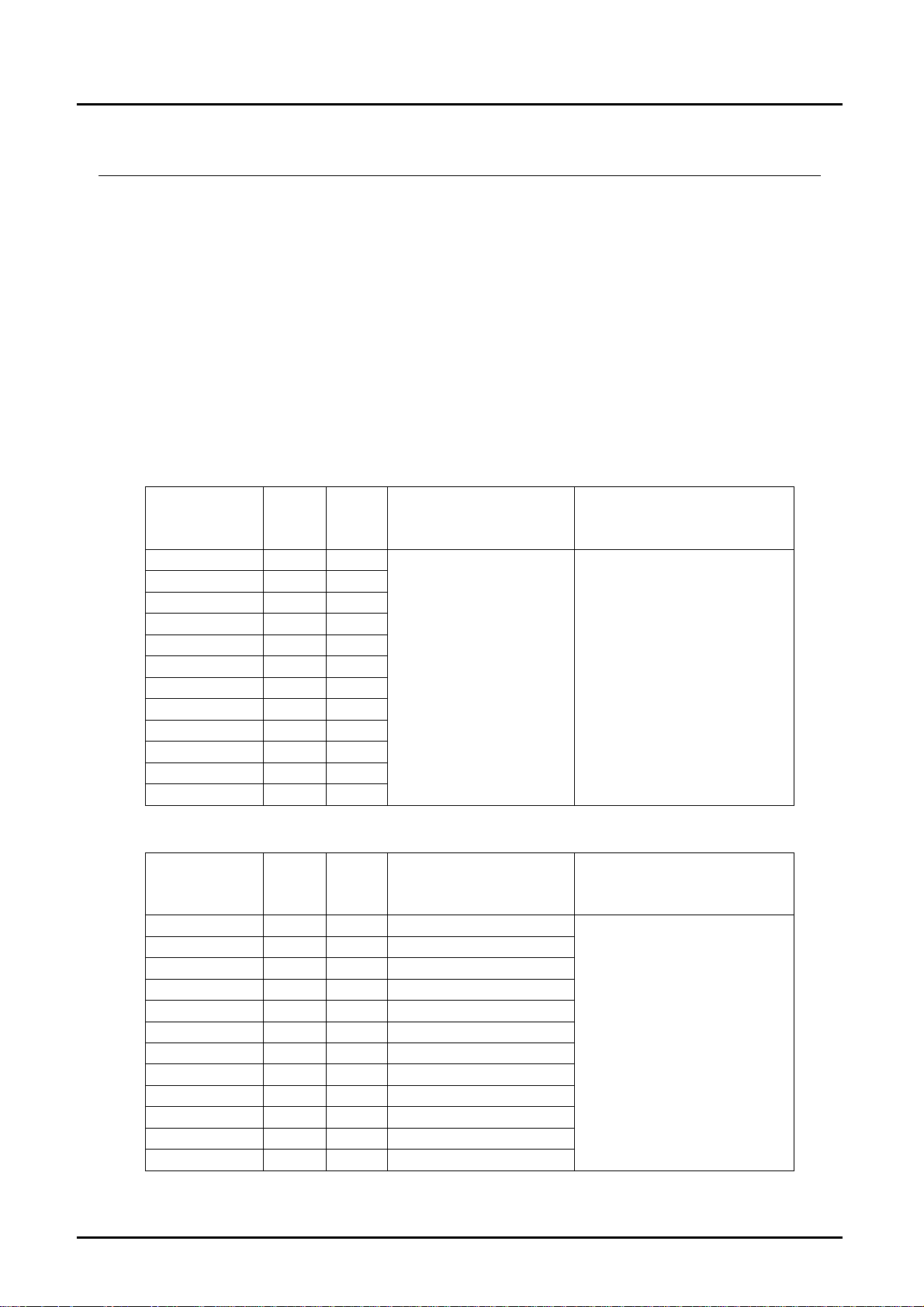
DON 1 Aluminum-Version
P
Model DON DN
DON-105 ⅛ 64
DON-110 ¼ 64
DON-115 ⅜ 64
DON-120 ½ 64
DON-125 25 64
DON-130 40 40
DON-135 50 40
DON-140 50 16
DON-145 80 16
DON-150 80 16
DON-155 100 16
DON-160 100 16
max
[bar]
diagram 8
group 1
dangerous liquids
§3 art.3 §3 art.3
DON 2/8 Stainless steel version
Model DON
2/8
DON-05 ⅛ 100 §3 Abs.3
DON-10 ¼ 100 §3 Abs.3
DON-15 ⅜ 100 §3 Abs.3
DON-20 ½ 100 §3 Abs.3
DON-25 25 100 category II
DON-30 40 50 category II
DON-35 50 50 category II
DON-40 50 16 category II
DON-45 80 16 category II
DON-50 80 16 category II
DON-55 100 16 category II
DON-60 100 16 category II
DN
P
max
[bar]
diagram 8
group 1
dangerous liquids
diagram 9
group 2
no dangerous liquids
diagram 9
group 2
no dangerous liquids
§3 art.3
DON K07/0815 page 3
Page 4
DON
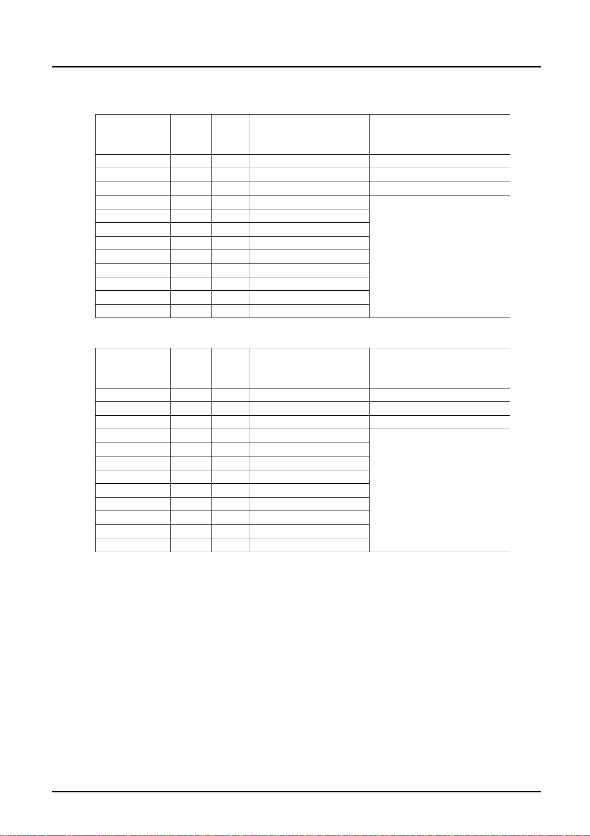
DON-1 M4 Aluminum version with mechanical totalizer
Option M4
Model DON-1
DON-05 ⅛ - - DON-10 ¼ - - DON-15 ⅜ - - DON-20 ½ 40 §3 art.3
DON-25 1 40 §3 art.3
DON-30 1½ 40 category II
DON-35 2 40 category II
DON-40 2 16 category II
DON-45 3 16 category II
DON-50 3 16 category II
DON-55 4 16 category II
DON-60 4 16 category II
DN
P
max
[bar]
diagram 8
group 1
dangerous liquids
diagram 9
group 2
no dangerous liquids
§3 art.3
DON 2/8 Stainless steel with mechanical totalizer
Option M4
Model DON
2/8
DON-05 ⅛ - - DON-10 ¼ - - DON-15 ⅜ - - DON-20 ½ 40 §3 art.3
DON-25 1 40 §3 art.3
DON-30 1½ 40 category II
DON-35 2 30 category II
DON-40 2 16 category II
DON-45 3 16 category II
DON-50 3 16 category II
DON-55 4 16 category II
DON-60 4 16 category II
DN
P
max
[bar]
diagram 8
group 1
dangerous liquids
diagram 9
group 2
no dangerous liquids
§3 art.3
page 4 DON K07/0815
Page 5

DON
3. Instrument Inspection
Instruments are inspected before shipping and sent out in perfect condition.
Should damage to a device be visible, we recommend a thorough inspection of
the delivery packaging. In case of damage, please inform your parcel service /
forwarding agent immediately, since they are responsible for damages during
transit.
Scope of delivery:
The standard delivery includes:
Oval Gear Flow Meter model: DON
Operating Instructions
Calibration Certificate
4. Regulation Use
The oval gear meter is a precise positive displacement flowmeter incorporating a
pair of oval geared rotors. These meters are capable of measuring the flow of a
broad range of clean liquids.
Stainless Steel flowmeters are suited to most water based products and
chemicals and aluminum meters are suitable for fuels, fuel oils, & lubricating
liquids. It is important to ensure that the medium to be measured is compatible
with the materials used in the instrument. (See section 10 "Technical Data") It is
also imperative to comply with the maximum permissible operating parameters
specified in the "Technical Data" section.
The flowmeter is available as a measurement transducer with pulse output or with
other forms of evaluation electronics. Details of how to operate the electronics are
included in a separate instruction manual.
These flowmeters DON can be installed within hazardous areas when ordered
with optional Exd approval, or by using the reed switch pulse output in Intrinsically
Safe loops or installing Intrinsically Safe certified Instruments.
Any use of the oval gear flow meter model: DON, which exceeds the
manufacturer’s specification, may invalidate its warranty. Therefore, any resulting
damage is not the responsibility of the manufacturer. The user assumes all risk
for such usage.
DON K07/0815 page 5
Page 6
DON
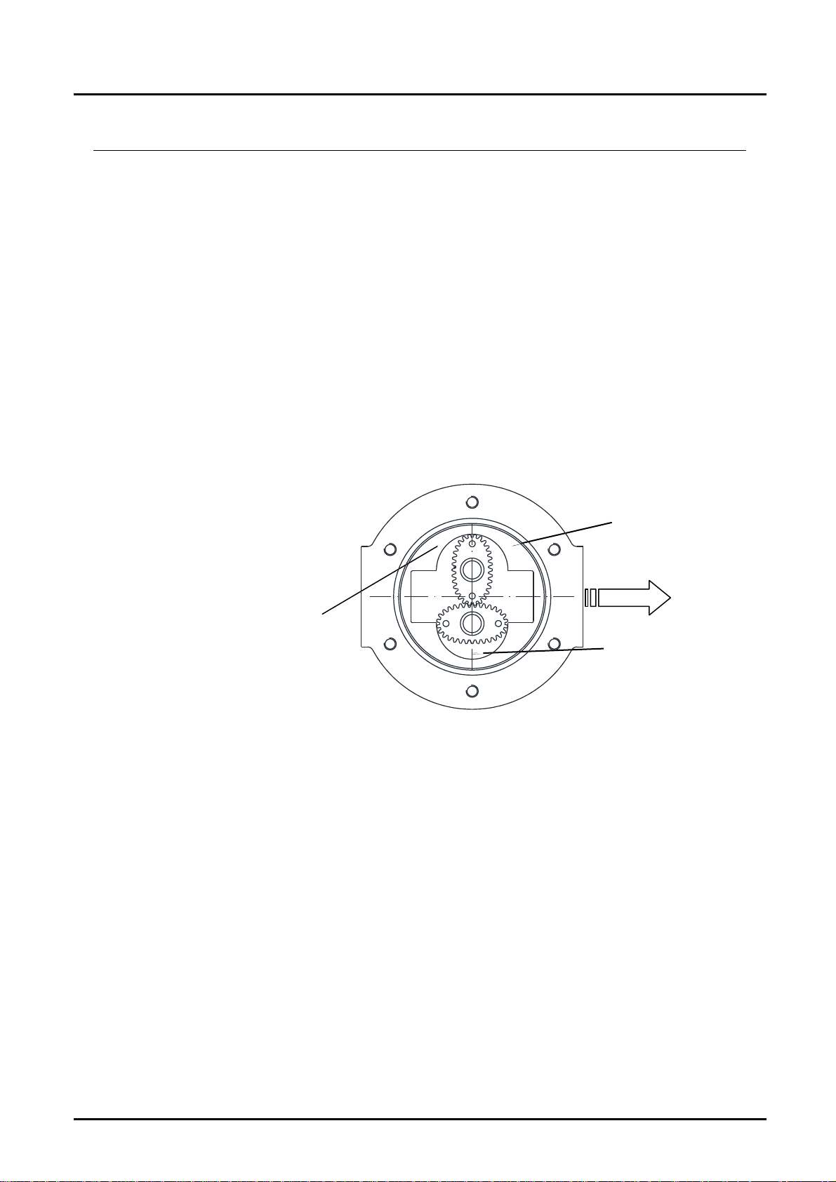
5. Operating Principle
Oval gear flowmeters are categorized as positive displacement flow technology.
When liquid flows through this type of positive displacement flowmeter, two oval
geared rotors measure a constant volume per rotation within a precisely
machined measuring chamber. With each rotation, a constant volume of liquid is
measured. The rotation of the oval gears is sensed via magnets embedded within
the rotors. These magnets transmit a high resolution pulse output. The output
signal can be process externally via a remote display controller or PLC or via a
variety of output/display options available as accessories attached to the
flowmeters.
The positive displacement flow technology allows for precise flow measurement
of most clean liquids regardless of the media conductivity. Other liquid properties
also have a minimal effect on the performance of this type of meter. Flow profile
conditioning is not required as with alternative flow technology options making
oval gear installations simple to install in tight spaces and at an economical price.
OPERATION:
Liquid travels around the crescent
shaped chambers created by the
rotational movement of the rotors
liquid entering
measuring chamber
liquid exits the
measuring chamber
liquid in transit
page 6 DON K07/0815
Page 7

DON
6. Mechanical Connection
6.1 General
Points to verify before meter installation:
Chemical compatibility of the liquid. Be sure that all wetted parts are
identified and confirmed suitable for use with the media being measured. If
unsure, please contact a KOBOLD engineer for guidance in obtaining the
proper reference materials.
Verify that the operational pressure and temperature limits are within
capability of the fully specified meter. Verify that the operational flow rates are
within the specified flow range. Viscous liquids may limit the maximum
allowable flow based on the viscosity. The max allowable flow rate may need
to be limited to ensure the differential pressure across the flowmeter does not
exceed 1 Barg, (100 kPa, 15 PSIG).
Be sure that the flowmeter is not subject to any process temperatures and/or
pressures that can cause the measured liquid to freeze or flash inside the
meter.
DON K07/0815 page 7
Page 8
DON
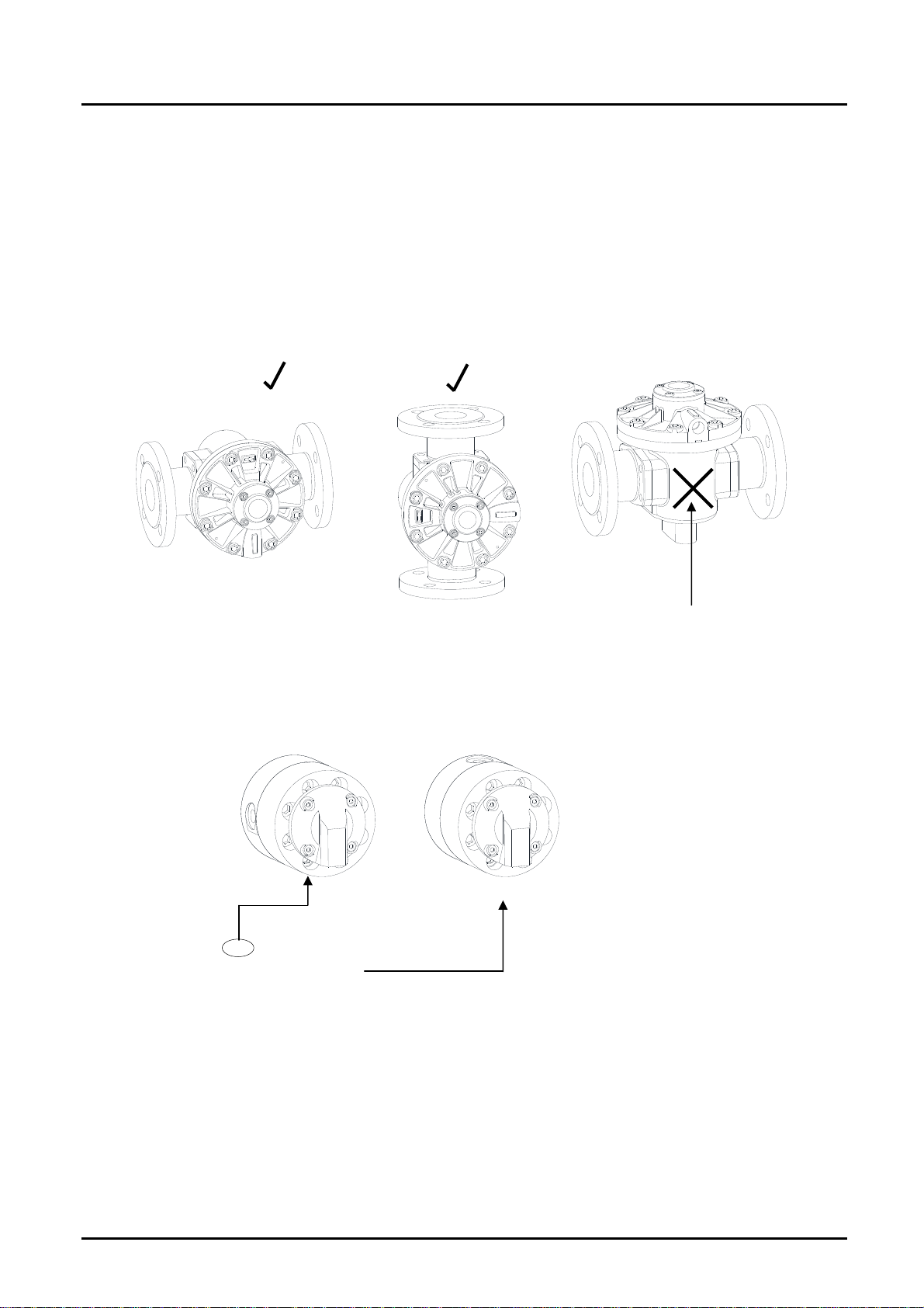
6.2 Orientation
When installing the flowmeter, orientation must be considered. The rotor shafts
must be in a horizontal plane. To verify that the rotor shafts are in a horizontal
plane, electronic cover or optional digital display will be facing in a horizontal
direction. For modification in the field, the electronic cover or digital display can
be rotated in any 90 degree position. This accommodates access to the electrical
entry and allows the electronic display orientation to best suit the installation.
C O R R E C T I N S T A L L A T I O N S
I N C O R R E C T
Incorrect installations will cause the
rotor weight to be felt on the bottom of
C O R R E C T I N S T A L L A T I O N S
Note: orient the conduit entry downward
to avoid moisture migration into the
electronic cavity.
the measuring cavity.
The DON flowmeter accommodates both horizontal and vertical flows. It is
recommended that for vertical flow installations that the liquid flow up through the
meter (i.e. bottom to top). This orientation assists in air or entrained gas removal.
Since the flowmeter operates in both flow directions there are no markings
showing inlet, outlet, or flow direction.
page 8 DON K07/0815
Page 9

DON
6.3 Flow Conditioning and Location
It is highly recommended to INSTALL a filter immediately before (prior to) the
meter. Filters are available and sold separately.
Recommended Filter:
DON-x05…DON-x15: < 75 µm particle size (200 mesh)
DON-x20…DON-x35: < 150 µm particle size (100 mesh)
DON-x40…DON-x60: < 350 µm particle size (45 mesh)
Flow conditioning: Flow conditions is not required since the DON flowmeter does
not require any straight pipe runs before or after the flowmeter.
Location: The recommended installation would be before of any flow control
and/or shut off valves, this installation prevents complete emptying of the meter.
This minimizes the risk of leakage and/or air entrapment which could result in
damage to the flowmeter or inaccurate initial readings.
A by-pass installation is recommended for process or safety critical meters.
Isolation valves enable the meter to be isolated from the system and serviced as
needed. System purging is also possible with a by-pass arrangement.
Accommodate all meter ratings and locate the meter on the discharge side of the
process pump.
For outdoor applications, be sure all electrical entries are sealed properly via the
proper glands, mounting, sealing or containment. For humid environments,
mount the instrument appropriately as to avoid condensation build up. Generally
these installations have the conduit connection pointing downward as to drain any
condensate away from the electronics.
Liquid State: Liquid within the flowmeter must not freeze. If heat tracing is
necessary, please be sure to adhere to the temperature limits of the flow meter.
Ensure the liquid does not flash, do not exceed the max DP of the flowmeter.
Hydraulic shock: Surge dampeners or pressure relief valves must be installed if
hydraulic shock or pressure spikes are present. Highly pulsating flow can also
damage the DON flowmeter. Diaphragm pumps and specific application profiles
can cause high frequency pulsating flow. Proper pulsating dampers are highly
recommend.
DON K07/0815 page 9
Page 10

DON
7. Electrical Connection
7.1 Connecting Cable
Proper shielded instrument cable is highly recommended. Low capacitance
twisted pair 7 x 0.3 mm (0.5 mm²) for use with the DON and any remote receiving
instrumentation. Typical cable would be Belden® 9363 or similar. Connect the
cable shield to DC common or designated grounding terminal at the receiving
instrument. Remember to only connect the end of the cable shielding at the
receiving instrument (not the DON) to ensure proper interference protection.
Please be sure not to run the connecting cable within a common conduit or in
close proximity to conduit with high inductive loads or power sources. This could
result in noise or inducted errors to the output signal or result in damage to the
electronic components. Always run the instrument cables in a separate conduit
or within a common conduit with other low power cables. Max cable length
should be limited to 3280 ft (1000 m).
7.2 Hazardous area wiring
The instrument can only be operated in the ATEX area as "Simple Apparatus" in
accordance with ATEX Article 1 §2 and 3 with the "Reed contact" (R0) option and
without ATEX labelling. For this purpose, intrinsically safe cabling must be laid
between the instrument, the hazardous area and an approved isolation switching
unit outside the hazardous area. (See section 14.)
Alternatively, the device can be operated using option E1 (dual counter) or E3
(flow controller) with Ex ia IIB T4 approval [see separate operating instructions] or
with explosion-protected housing (Exd) option RE, BE, GE, LE, HE or DE. Only
Exd-certified cable conduits and cable glands with corresponding temperature
limits may be used. Hall-effect sensor output is not possible if the DON flowmeter
is operated in an ATEX zone as simple apparatus or using the E1/E3 option.
When operating the electronic options LE, BE, GE, RE, HE and DE, suitable
operating materials must be used to ensure that the maximum operating
voltage of 28 VDC and the maximum operating current of 200 mADC are not
exceeded.
The wiring methods used must be in accordance with the applicable rules,
provisions and requirements at the location where the device is installed. The
measuring devices may only be connected by qualified personnel who are
familiar with the protection classes, provisions and specifications for the device in
areas at risk of explosion.
page 10 DON K07/0815
Page 11
DON
7.3 Electrical connection for integrated electronics options
The electrical connection of the integrated electronics options always requires the
electronics cover to be dismantled. Models from size X05 to X20 incorporate the
cable inlet into the electronics cover, while models from the X25 size onwards
accommodate the cable inlet in the housing cover.
The use of an EXD-certified cable gland is imperative for explosion-protection
options HE, GE and LE (M20x1.5 or ½" NPT) (not included in delivery). The
connecting cable must be routed through the cable duct and connected in
accordance with 7.3.1 to 7.3.4. The connecting terminals are of the plug-in type,
and can be taken out of the terminal compartment to facilitate connection.
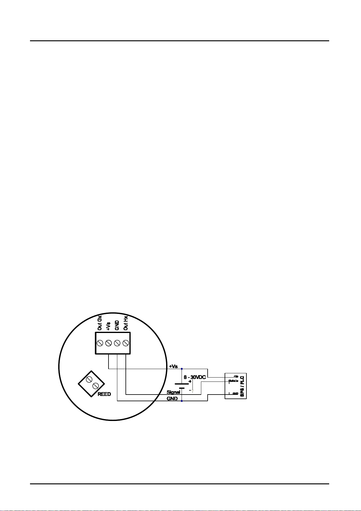
7.3.1 Hall-effect sensor with active pulse output + reed contact
(H0/HE/B0/BE/ options)
The H0/HE/B0/BE electronics options combine a hall-effect sensor with an active
push-pull output stage. The B0/BE options involve combining bipolar Hall sensors
with alternating polarised magnets. This option is particularly suitable for
pulsating currents, although the pulse rate is halved compared to the H0/HE
option. A three-phase electrical connection is used. The output is actively
switched, either to the input terminal voltage +Vs or to GND. The external input
terminal voltage is 8 to 30 Vdc. No additional external wiring is required (e.g. pullup resistor). The high signal corresponds approximately to the +Vs input terminal
voltage and the low signal approximately to 0 V.
The electrical load can be connected to either the input terminal voltage or GND
Max. output current (power source or sink): 100 mA (short-circuit protected).
The hall-effect sensor pulse output is not available if a device is ordered for use in
the explosion hazard area as "Simple Apparatus" (e.g. if the "E1" option is
ordered).
DON K07/0815 page 11
Page 12
DON
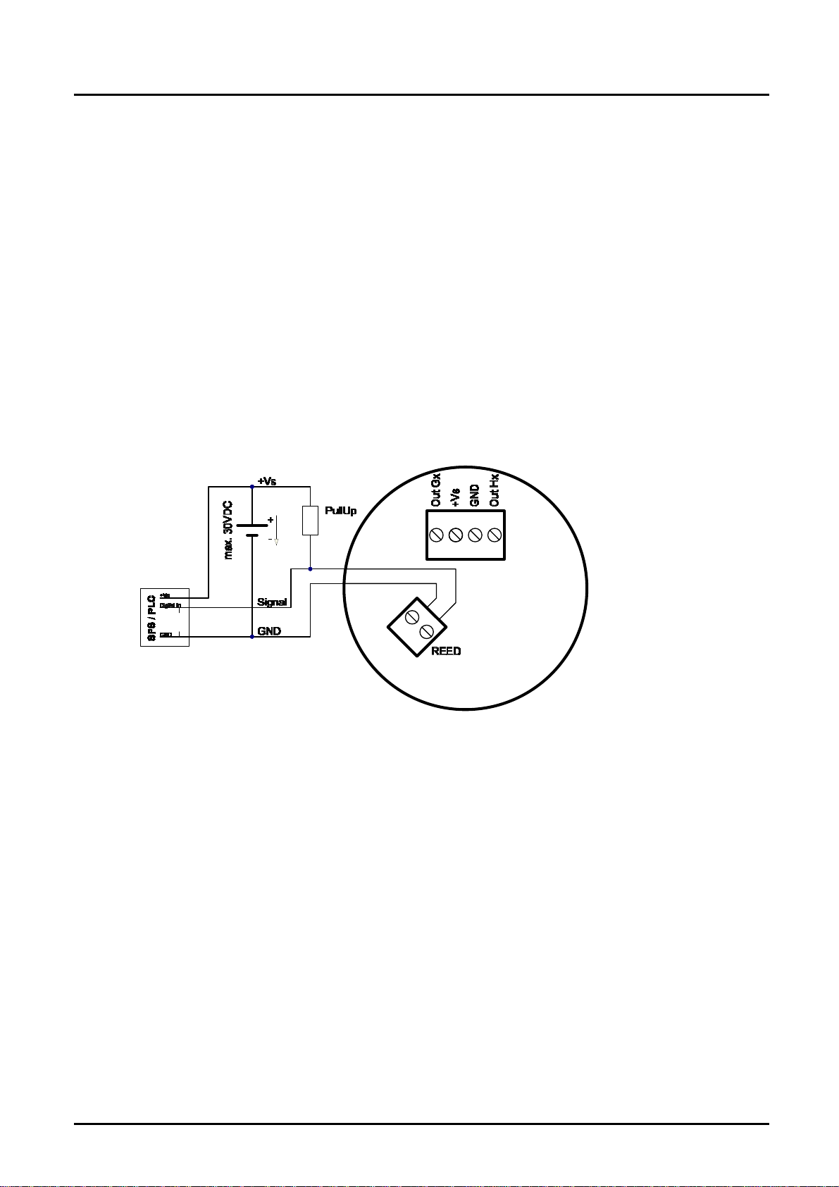
7.3.2 Reed Switch Pulse Output
The DON reed switch output is a SPST potential free N/O 2-wire output. This is a
passive output so no power is required. The output may also be used with an
appropriate intrinsically safe barrier for use in hazardous locations. If the intention
is to operate the dry-reed contact impulse output in ATEX areas as simple
apparatus, only the R0 option may be used. Note: when using the reed switch
output the liquid temperature must not change at a rate greater than 10 ºC per
minute (50 ºF per minute).
Average electrical endurance of switching contact (MTTF - Mean Time To First
Failure):
Max. switching voltage (100 V/10 mA) 5x10⁵ switching cycles
6
Max. current load (20 V/500 mA) 5x10
Min. load (<5 V/10 mA) 5x10
Switching capacity: Max. 30 V
8
switching cycles
DC
switching cycles
, max. 200 mA
DC
page 12 DON K07/0815
Page 13
DON
The individually specified maximum electrical values of the reed switch must
never be exceeded, even for a moment. Higher switching values may reduce the
service life or even destroy the contact.
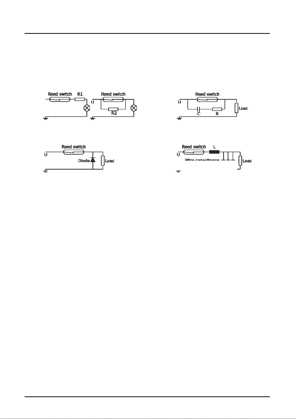
For capacitive and inductive loads (e.g. via long lines), we recommend the
following protective circuits:
Lamp load with series or parallel Protection with a RC suppressor
resistance to the reed switch. for a.c. current and inductive load.
Protection with a diode Protection with an inductance or
for d.c. current and inductive load. resistance for capacitive load.
DON K07/0815 page 13
Page 14
DON
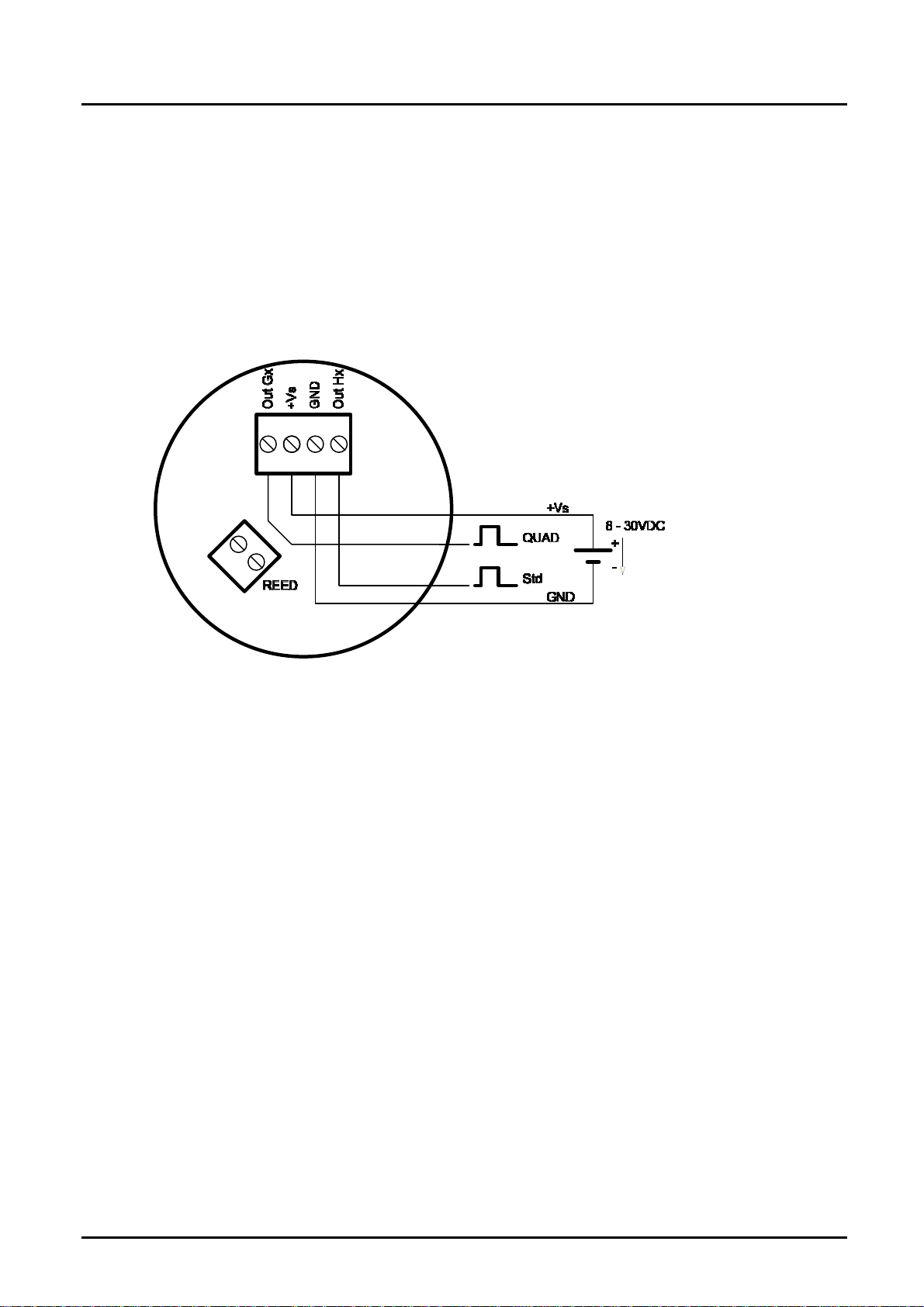
7.3.3 Quadrature Pulse Output (QUAD, Option D0/DE)
For the D0/DE option, the DON devices come with 2 independent hall-sensor
elements. The hall-effect sensors are arranged so that they emit separate phaseshifted signals to one another.
The QUAD output is best-suited for verified use with a redundant signal or for
counting bidirectional currents (detecting the current direction).
Max. output current per channel (power source or sink): 100 mA (short-circuit
protected).
The current direction of the medium is defined as follows:
a.) Hx signal leading over Gx signal: Current flowing in the direction of the
marked arrow (positive)
b.) Hx signal lagging behind Gx signal: Current flowing against the direction of the
marked arrow (negative)
page 14 DON K07/0815
Page 15
DON
7.4 Internal wiring with electronic options -Ex/Zx
The Ex/Zx electronic options are pre-configured ex works in connection with the
sensor boards. Reconfiguration is available on request.
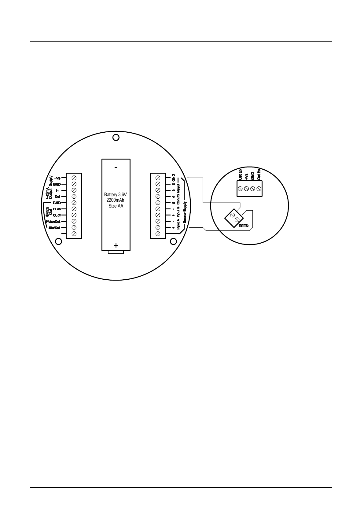
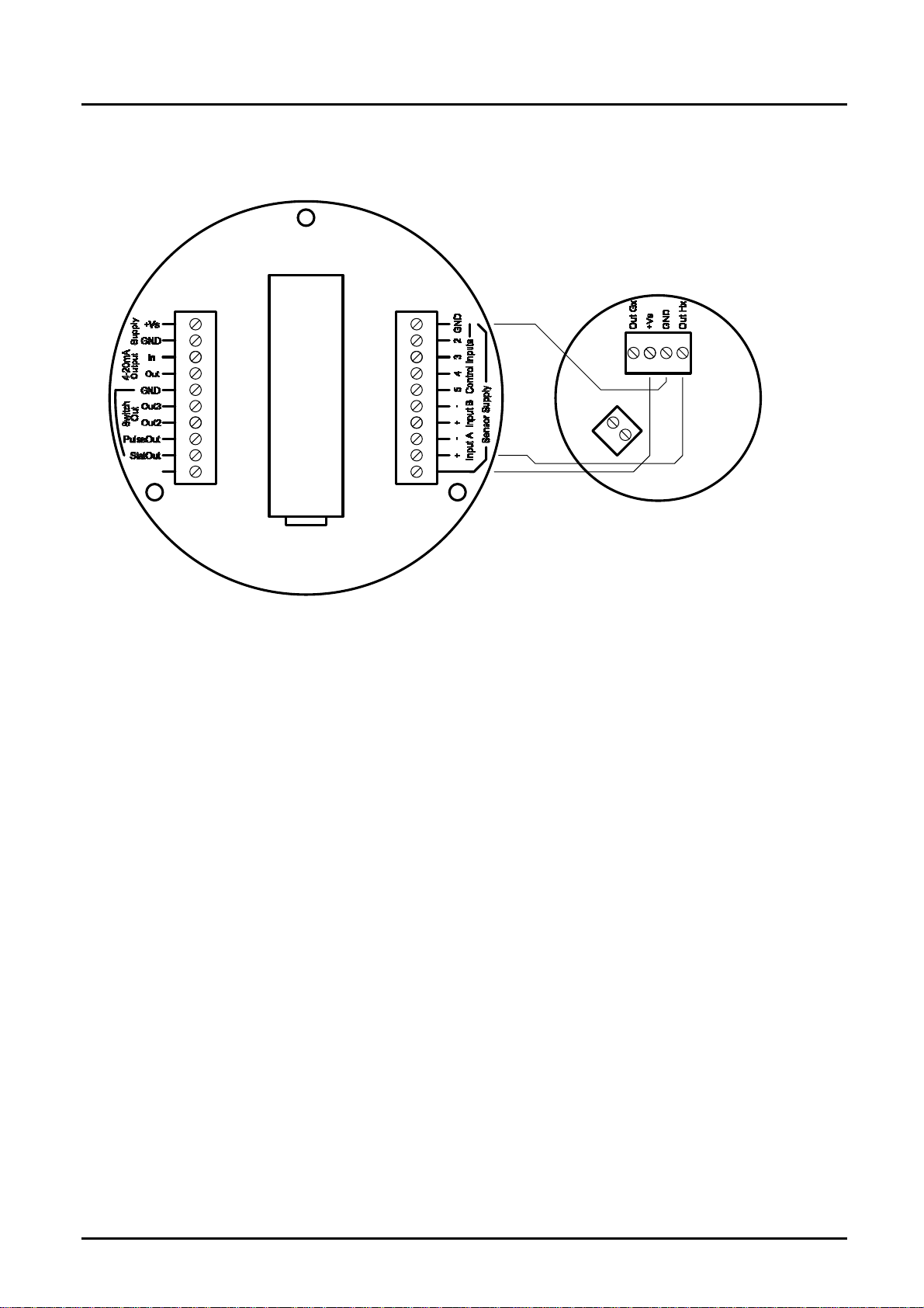
7.4.1 For Z1/Z3 electronic options (reed switch and Hall sensor)
a) Wiring diagram with reed switch (ex works standard)
DON K07/0815 page 15
Page 16
DON
b) Wiring diagram with Hall sensor (recommended in connection
with external supply)
-
Battery 3,6V
Battery 3,6V
2200mAh
2200mAh
Size AA
Size AA
+
7.4.2 For Z6/Z7 electronics options (bipolar Hall sensor)
The circuitry corresponds to 7.4.1 b.)
7.4.3 For E1/E3 electronics options
The wiring is exclusively implemented with a reed switch (see 7.4.1.a). Within this
wiring, the reed switch operates as simple apparatus and may be used in Zone 1.
page 16 DON K07/0815
Page 17

DON
7.4.4 For Z2/Z8/Z9 electronics options (2 Hall sensors for direction
detection)
DON K07/0815 page 17
Page 18

DON
7.4.5 Analog output 4-20 mA, 2-line (L0/LE option)
The L0 and LE (explosion hazard) options include a loop-powered 4-20 mA
output. The loop is powered by an external voltage source 16 – 32 VDC. The
maximum working resistance of loads connected in series (PLC-analogue input /
electronic displays) depends on the supply voltage level, namely:
Max. working resistance (ohms) = (+Vs – 9 VDC) / 0.02 A [ohms]
Example: +Vs = 32 VDC => max. working resistance = 1150 ohms
+Vs = 16 VDC => max. working resistance = 350 ohms
The load can be coupled at any point of the current loop, provided the polarity is
correct.
All DON devices with L0/LE options are factory-calibrated to the respective
measurement range end value. This setting should only be modified by the
manufacturer.
7.4.6 Calibration Factor (scale or K Factor)
The DON flowmeter is delivered with a factory calibration certificate. Within this
certificate, a calibration factor is provided. The calibration factor is a specific
representation of pulses per unit volume. (i.e. pulses per liter) for that specific
meter.
Measurement devices with attached electronics are factory pre-configured to the
corresponding calibration factor. Depending on the model, the calibration protocol
is based on either the flow rate display or the analog output.
Please reference the appropriate digital display manual for programming details.
page 18 DON K07/0815
Page 19

DON
7.5 External wiring with electronic unit ZOK-Zx
7.5.1 Wiring with ZOK-ZxK
a) Circuit with Hall sensor (not for battery operation)
b) Circuit with Reed switch
DON K07/0815 page 19
Page 20

DON
7.5.2 Wiring with ZOK-ZxP
a) Circuit with Hall sensor
b) Circuit with Reed switch
page 20 DON K07/0815
Page 21

DON
8. Commissioning
The piping MUST be flushed of debris before installation. Debris such as slag
from welding, grinding dust, rust, pipe tape or sealing compound are common
within new piping installations and will damage the flowmeter if not flushed or
filtered from the process piping before installation and operation.
A by-pass system is common for frequent system flushing or frequent meter
removal. If a by-pass system is not practical or possible, removal of the gears
before flushing is necessary. (refer to section 9.1 “Disassembly of Pulse meter”).
For proper operation the flowmeter must be purged of air. During long periods of
inactivity or after a flushing, air may be in the piping. Elimination of the air may
be achieved by operating the meter at a low flow rate until all the air is eliminated.
Damage may occur to the flowmeter if it is run above the maximum rated flow
rate or if the maximum differential pressure of 15 psi (1 bar, 100 kPa) is
exceeded.
After mechanical and electrical installation according to the guidelines set forth
within this user manual, the DON flowmeter is ready for operation.
DON K07/0815 page 21
Page 22

DON
9. Maintenance
Flowmeter maintenance precautions:
Remove/disconnect power to the flowmeter.
Ensure that flow supply to the meter is turned off and the system is not
under pressure.
Completely drain the flowmeter
Confirm that any signal output(s) will not affect the system when de-
energized or removed from the circuit.
Oval gear positive displacement flowmeters are mechanical by nature. A periodic
maintenance/inspection schedule is suggested for an extended service life.
Follow the guidelines within this user manual for the maximum flowmeter
performance.
The maintenance/inspection schedule should be determined based off of
application factors such as media type (abrasiveness, lubricity, and/or chemical
compatibility), flow rate, and operating/maximum temperature and pressure.
page 22 DON K07/0815
Page 23

DON
9.1 Disassembly of DON with Pulse meter (Options Hx, Dx, Gx,
Bx and Rx)
9.1.1 Pulse output board removal (refer exploded view diagram)
To remove the pulse output board, remove the 4 electronic cover screws (10),
and remove the electronic cover (9). The pulse output board (6) can now be
accessed and removed via the removal of the electronic board screws (7).
9.1.2 Oval gear removal for DON-x05…DON-x15 (refer exploded view
diagram)
For access to the oval gears, remove the 4 lower meter body screws (5). With
care, remove the upper meter body assembly (4) being careful not to damage or
misplace the O-ring (3). You can then remove the oval gears (2).
For DON models DON-x05 to DON-x15, when disassembling, please notice the
dimples located on the meter bodies (1 & 4) face just outside the o-ring groove.
The referencing dimples must be in alignment when reassembling.
1
Assembly alignment
dimple
5
2
3
4
7
2
6
Optional
8
9
10
DON K07/0815 page 23
Page 24

DON
9.1.3 Removal of oval gears for DON-x20 (refer exploded view)
For access to the oval gears, remove the 6 upper meter body screws (5). With
care, remove the upper meter body assembly (4) being careful not to damage or
misplace the O-ring (3). You can then remove the oval gears (2).
Optional
page 24 DON K07/0815
Page 25

DON
9.1.4 Removal of oval gears for DON-x25…DON-x40 (refer exploded
view)
For access to the oval gears, remove the 8 upper meter body screws (5). With
care, remove the upper meter body assembly (4) being careful not to damage or
misplace the O-ring (3). You can then remove the oval gears (2).
2
8
1
7
6
9
10
2
11
3
4
5
12
13
Optional
DON K07/0815 page 25
Page 26

DON
9.1.5 Removal of oval gears for DON-x45…DON-x60 (refer exploded
view)
For access to the oval gears, remove the 8 upper body screws (5). With care,
remove the upper body assembly (4) being careful not to damage or misplace the
O-ring (3). You can then remove the oval gears (2).
Optional
page 26 DON K07/0815
Page 27

DON
9.1.6 Structure of the DON-M4 mechanical counting mechanism
Loosen three screws (10)
Remove cover (9)
Lift out counting mechanism (8)
Remove seal (7)
Loosen 4 screws (6)
Remove lower housing section (5)
Remove seal (4), washer (3) and seal (2).
When assembling, it is important to ensure the oval gear of (3) is correctly
positioned relative to the counting mechanism (8). When mounting the counter
mechanism, it is preferable to keep the DON in a horizontal position. This allows
the counter mechanism (8) to be mounted distortion-free from above on the cone
gear wheel (3).
DON-x20
DON K07/0815 page 27
Page 28

DON
DON-x25 to x40
DON-x45 to x60
page 28 DON K07/0815
Page 29

DON
9.1.7 Adjusting the DON-M4 mechanical counter mechanism
The M4 mechanical counter display comprises a 4-digit mechanical totalizer (1)
and an 8-digit sum display (2). Depending on the order option, the display is
calibrated in either litres or gallons.
The totalizer display can be reset to zero by turning the function dial (3) in an anticlockwise direction.
3
1
2
DON K07/0815 page 29
Page 30

DON
9.2 Demounting of the electronics mounted on a DON with Zx
9.3 Spare Parts
and Ex options
To access the device battery, terminal connections and pulse output board, the
electronic cover with display must first be removed in case of flowmeters with
built-in electronics. To do this, loosen the 4 screws of the display cover and
carefully remove it without pulling out or damaging the connecting cable. During
this procedure, be careful not to lose or damage the O ring. The terminal
connection, device battery and pulse output board are now freely accessible. To
remove the electronics, the screws used to connect the electronics housing to the
oval gearbox housing should be loosened.
Please consult your closest KOBOLD-Office
Internet: www.kobold.com or www.koboldusa.com
9.4 Inspection (refer Exploded View)
Inspection points will be the following:
O-rings – Inspect for physical or chemical damage or deformation.
Rotors – Inspect for physical damage due to unfiltered media or damage due to
chemical attack. Also observe also the magnets, if exposed, for chemical attack.
Measuring Cavity – Inspect for physical damage (scoring) due to improperly
filtered media or long term wear and tear.
Axle Shafts – Inspect for physical damage and ensure that the shafts are not
loose and do not rotate.
9.5 Re-assembly of DON
Before re-assembly, please be sure to thoroughly clean all parts.
Care must be taken when reinstalling the rotors such that the magnets should
face the pulse output board.
page 30 DON K07/0815
Page 31

DON
9.5.1 Re-assembly of DON-x05...DON-x15
For DON models DON-x05 to DON-x15, when re-assembling, please insert the
rotor with the embedded magnet nearest to the dimple located on the meter body
face just outside the o-ring groove. Install the rotors exactly perpendicular from
each other (90° in orientation). They will only work if installed precisely. Manually
test full rotation after installation as the rotors will not completely rotate freely
unless installed precisely 90° from each other.
Proper placement of the O-ring within the groove is necessary for leak free
operation. After placement, items (1 & 4) will then require assembly. For the
small 4 mm and 6 mm flowmeters, reference the alignment dimples on the lower
meter body and upper meter body (1 & 4) for proper assembly.
Tighten the meter bodies (1 & 4) with the screws (5) in an alternating pattern (1,
3, 2, 4). Tighten to each to a torque of 3.5 Nm. The alternating tightening
procedure is preferred for proper and even assembly.
Install the pulse output board, the o-ring into the provided groove, and then install
either the pulse output board cover (9) or optional electronic assembly.
5
2
3
Assembly alignment
1
2
4
7
dimple
6
Optional
8
9
10
DON K07/0815 page 31
Page 32

DON
9.5.2 Re-assembly of DON-x20...DON-x40
Both oval gears are placed on the axle shafts with the magnets oriented towards
the upper meter body (4). Verify that the axle shafts are not loose. Both oval
gears are equipped with embedded magnets, allowing them to each be mounted
on either axle.
Install the rotors exactly perpendicular from each other (90° in orientation). They
will only work if installed precisely. Manually test full rotation after installation as
the rotors will not completely rotate freely unless installed precisely 90° from each
other.
Proper placement of the O-ring within the groove is necessary for leak free
operation. After placement, items (1 & 4) will then require assembly.
Tighten the upper meter body to the lower meter body (1 & 4) with the screws (5)
in an alternating pattern (1, 3, 2, 4). Tighten to each to a torque of 3.5 Nm. The
alternating tightening procedure is preferred for proper and even assembly.
Install the pulse detector board, the o-ring into the provided groove, and then
install either the electronic cover (9) or optional electronic assembly.
Exploded view of DON-x25...DON-x40
2
8
1
2
11
12
page 32 DON K07/0815
3
4
5
13
6
7
Optional
9
10
Page 33

DON
Exploded view of DON-x45...DON-x60
Optional
10. Technical Data
Material:
DON-1
Body: aluminum
Oval gears: PPS GF 30/PTFE
Axes: stainless steel 1.4404
DON-2
Body: stainless steel 1.4404 DON-x05…DON-x15
stainless steel 1.4404/1.3955
DON-x20…DON-x60
Oval gears: stainless steel 1.4404 DON-x05…DON-x40
stainless steel 1.3955 DON-x45…DON-x60
Bearing: carbon graphite
Axes: stainless steel 1.4404
DON-8
Body: stainless steel 1.4404 DON-x05…DON-x15
stainless steel 1.4404/1.3955
DON-x20…DON-x60
Oval gears: PPS GF 30/PTFE
Axes: stainless steel 1.4404
DON K07/0815 page 33
Page 34

DON
O-Rings: medium temperature
FKM: -20..+120 °C, NBR: -20..+100 °C
FEP-O-seal/FKM: -25…+130 °C
Cover for cable connection: polyamide PA6 GF35 UL94 HB/VO DON-1
stainless steel 1.4404 DON-2 und DON-8
Accuracy: ± 1 % of reading (DON-x05..DON-x15)
± 0.5 % of reading (DON-x20..DON-x60)
± 0.2 % of reading (DON-x20..DON-x60);
with optional Z3/E3-electronics based on
linearization function
± 1 % of reading (option M)
Additional max. inaccuracy for
analog outputs: ± 0,15 % ME
Repeatability: typ. ± 0.03 %
Protection class: IP 66/67 (IP65 for M4)
Medium temperature: -20...+80 °C for options –L0, Z, M4
and -20 °C…+120 °C for pulse output
and options Z with cooling fins
Ambient temperature: -20...+80 °C, option M4 0 °C…+60 °C
Cable entry: M20x1.5, ½“ NPT
ATEX approval
(option E1/E3): II 2G EEx ia IIB T4 (-20 °C ≤ Ta ≤ + 60 °C)
(option HE, BE, DE,
GE, LE, RE): II 2G Ex d IIC T6 (-20 °C ≤ Ta ≤ + 70 °C)
II 2G Ex d IIC T4 (-20 °C ≤ Ta ≤ + 120 °C)
I M2 Ex d I Mb (st. steel models only)
R0/RE electronics options: max. switching voltage: 30 V
(Reed switch pulse output) max. switching current: 200 mA
DC
max. switching capacity:10 W
Service life: > 2*10
(at 5 V
6
switching cycles
and 10 mA)
DC
H0/HE/B0/BE electronics options:
Supply voltage: 8 to 30 V
DC
(Hall sensor + reed switch Supply current: max. 5 mA (without load)
pulse output) Hall pulse output: active push-pull, max.
(B0/BE not for x05) 100 mA, short-circuit proof
HIGH level:
Min. +Vs - 1.3 V
LOW level: max. 1.3 V
Reed pulse output: as for R0/RE
G0/GE electronics options: Supply voltage: 8 to 30 V
DC
(Pulse output hall sensor Supply current: max. 8 mA (without load)
High resolution, only X05/X10) Hall pulse output: like H0/HE
page 34 DON K07/0815
Page 35

DON
D0/DE electronics options: Supply voltage: 8 to 30 V
(2x Pulse output hall sensor) Supply current: around 8 mA
DC
DC
Hall pulse output: like H0/HE
Current direction: positive: Hx leading over
QUAD
negative: QUAD leading
over Hx
L0/LE electronics options: Supply voltage: 16 to 32 V
DC
(Current output 4-20mA) Analog output: 4 20 mA, 2-wire
Max. working resistance: 750 ohms (at 24 VDC)
Z1/Z2/Z3 electronics options (common properties):
Supply voltage: 8 to 32 VDC
Battery operation (only Z1/Z3)
Battery: 3.6 V/2200 mA AA size
Display: LCD, graphic 128x64
Backlighting adjustable
Operation: 4 buttons
Housing: plastic, PA6,
GF-reinforced
Cable inlet: 3x M20x1.5, prepared
Electrical connection: plug-in terminals
Z1 electronics option: Signal inputs: 2x, configurable
(Dual counter) Daily/overall counter: 1x per input
Signal outputs: none
Z2 electronics option: Signal inputs: 1x, configurable
(Batching device) Batching function: 2-stage
Signal outputs: relay output
Z3 electronics option: Signal inputs: 2x, configurable
(Flow controller) Signal outputs: current output 4-20 mA
2-wire / 3-wire
pulse output, scalable
status output
Max. working resistance of current output:
750 ohms (at 24VDC)
M4 mechanical counter: 4-digit quantity indication
in litres or gallons
8-digit sum display
DON K07/0815 page 35
Page 36

DON
Maximum Pressure (threaded version)
Maximum pressure (bar)
Model
DON-1 DON-2/8
DON-1..
(option -
M4)
DON-2/8
(option –
M4)
DON-x05
DON-x10 - -
DON-x15 - -
DON-x20
DON-x25
DON-x30
DON-x35 30
DON-x40
DON-x45
DON-x50
DON-x55
DON-x60
with flanges, maximum pressure rating is above or as per flange rating, whichever is lower
Max. Flowrate Multiplier (for higher viscosities)
Viscosities
(cP)
≤ 1000 1 1
≤ 2000 0,5 1
≤ 4000 0,42 0,84
≤ 6000 0,33 0,66
≤ 8000 0,25 0,5
≤ 30000 0,15 0,3
≤ 60000 0,12 0,25
≤ 150000 0,1 0,2
≤ 250000 0,05 0,1
≤1000000 0,025 0,05
Special cut rotors for higher viscosities
For viscosity > 1000 cP, special cut rotors option „S“ should
be used to reduce pressure drop. This applies to DON-x15
and larger sizes. For higher viscosities, the flowmeter
max. flowrate is de-rated according to the attached chart.
Example: DON-x25 measuring oil at 8 000 cP,
max. flow 150 LPM x 0.5 = 75 LPM new maximum flow rate.
64 100
40 50
16 16 16 16
Standard rotor Special cut rotor
- -
40
40
page 36 DON K07/0815
Page 37

DON
Output Pulse Resolution
Measuring
Model
DON-X05 0,5 - 36 L/h 2670 2670 - 2670
DON-X10 2 - 100 L/h 1054 1054 - 1054
DON-X15 15 - 550 355 710 355 710 -
DON-X20 1-40 82 163 82 163 -
DON-X25 10 - 150 26 103 52 52 -
DON-X30 15 - 250 14 55 27 27 -
DON-X35 30 - 450 6,4 25,5 13,5 13,5 -
DON-X40 50 - 580 4,9 19,6 9,8 9,8 -
DON-X45 35 - 750 2,57 10,3 5,15 5,15 -
DON-X50 50 - 1000 1,5 5,9 3 3 -
DON-X55 75 - 1500 1,05 4,2 2,1 2,1 -
DON-X60 150 - 2500 0,56 2,3 1,15 1,15 -
range
[l/min]
The values in above mentioned table are only approximate guidelines. The actual
value for pulse rate can deviate up to +/- 3% from the values in this table and is
mentioned in calibration certificate delivered with the flowmeter.
Reed
switch Rx
Hall sensor
Hx
Pulse / liter
Hall sensor
Bx
Quadr.
hall sensor
Dx
Hall sensor
high resolution
Gx
11320
4210
DON K07/0815 page 37
Page 38

DON
11. Pressure drop curves
800
[mbar]
700
X05/X10
1000cPa
600
500
400
300
200
100
0
0 102030405060708090100
1500
[mbar]
1400
1300
1200
1100
X15/X20
1000cPa
500cPa
500cPa
200cPa
100cPa
10cPa
5cPa
3cPa
1cPa
0,5cPa
[%FS]
1000
900
800
700
600
500
400
300
200
100
0
0 102030405060708090100
200cPa
100cPa
10cPa
5cPa
3cPa
1cPa
0,5cPa
[%FS]
page 38 DON K07/0815
Page 39

DON
1000
[mbar]
900
X25/X40
800
700
600
500
400
300
200
100
0
0 102030405060708090100
800
[mbar]
700
1000cPa
X45/X60
500cPa
200cPa
100cPa
10cPa
5cPa
3cPa
1cPa
0,5cPa
[%FS]
1000cPa
600
500cPa
500
200cPa
400
300
200
100
0
0 102030405060708090100
100cPa
10cPa
5cPa
3cPa
1cPa
0,5cPa
[%FS]
DON K07/0815 page 39
Page 40

DON
12. Order codes
Measuring
range
[l/min]
0.5 – 36 l/h
2 – 100 l/h
15 – 550 l/h
1 – 40
10 – 150
15 – 250
30 – 450
50 – 580
35 – 750
50 – 1000
75 – 1500
150 - 2500
Example: DON-105H R1 1 L0 M 0
Housing material
Aluminium
with PPS
Rotor
DON-105H DON-205H DON-805H
DON-110H DON-210H DON-810H
DON-115H DON-215H DON-815H
DON-120H DON-220H DON-820H
DON-125H DON-225H DON-825H
DON-130H DON-230H DON-830H
DON-135H DON-235H DON-835H
DON-140H DON-240H DON-840H
DON-145H DON-245H DON-845H
DON-150H DON-250H DON-850H
DON-155H DON-255H DON-855H
DON-160H DON-260H DON-860H
1)
only for DON-x35 2) only for DON-x05 and DON-x10 3) only for options Ex/Zx
Stainless
steel
St. st. with
PPS rotor
Connection
R1 = G ⅛
N1 = ⅛ NPT
R2 = G ¼
N2 = ¼“ NPT
R3 = G ⅜
N3 = ⅜“ NPT
R4 = G ½
N4 = ½“ NPT
R6 = G 1
N6 = 1“ NPT
F6 = DIN- flange
PN 40
(DN 25)
A6 = ANSI-
flange
150 lbs (1“)
B6 = ANSI flange
300 lbs (1“)
R8 = G 1½
N8 = 1 ½“ NPT
F8 = DIN-flange
PN40 (DN40)
A8 = ANSI flange
150 lbs (1 ½“)
B8 = ANSI flange
300 lbs (1 ½“)
R9 = G 2
N9 = 2“ NPT
F9 = DIN-flange
PN40 (DN50)
A9 = ANSI flange
150 lbs (2“)
1)
= ANSI-
B9
flange
300 lbs (2“)
RB = G3
NB = 3“ NPT
FB = DIN-flange
PN 16 (DN80)
AB = ANSI flange
150 lbs (3“)
RC = G4
NC = 4“ NPT
FC = DIN-flange
PN16
(DN100)
AC = ANSI flange
150 lbs (4“)
O-Ring
Material
1 = FKM
3 = FEP-
Coated
FKM
4 = NBR
Electronics
L0 = 4…20 mA
„loop“
powered“
analog
output
LE = as L0 +
ATEX (Exd)
R0 = Reed
switch
pulse output
RE = reed switch
Pulse output
ATEX (Exd)
H0/B0 = hall
sensor
(Push-Pull)/
reed switch,
pulse
output
HE/BE = as H0
+ ATEX (Exd)
2)
= hall-
G0
sensor
(Push-Pull),
high resolution
2)
= as G0 +
GE
ATEX (Exd)
D0 = Quad. Hall
sensor
2 phased
outputs
(Push-Pull),
DE = as D0 +
ATEX (Exd)
Z1 = dual LCD
totalizer
Z2 = Batching
unit LCD
Z3 = LCD
totalizer/
rate,
output:
4-20 mA,
alarm, pulse
(ZOK-Z3)
(pulses
not for
battery
supply
Z6 = Z1 + B0
Z7 = Z3 + B0
Z8 = Z1 + D0
Z9 = Z3 + D0
E1 = as Z1 +
ATEX (Exi)
E3 = as Z3 +
ATEX (Exi)
M4 = mech.
totalizer
4-digit
Cable
gland
0 = without
(only for
option
M4)
M = M20
N = ½“ NPT
S = M20 +
cooling
3)
fin
T = ½“ NPT
+ cooling
fin
Option
0 = without
K = check valve
(from
DON-x30)
S = special
cut rotor
for higher
viscosities
Y = special
option,
(specify in
clear text)
page 40 DON K07/0815
Page 41

DON
13. Dimensions Electronic Options Ex/Zx
Option -M/-N (standard)
Option -S/-T (with cooling fin)
DON K07/0815 page 41
Page 42

DON
14. T roubleshooting
Oval gear flowmeters have two clearly distinct portions: one of which is
mechanical, wetted areas with the oval gears surrounded by a housing, and the
other is the electrical area, which includes the pulse output board.
Details of some key troubleshooting steps will now be provided. Please also refer
to the instructions on troubleshooting errors contained on the following page.
Step 1 - Check application, installation and set-up.
Carefully read the section on mechanical installation to ensure full knowledge of
all relevant installation and application factors which may affect the operation of
the counter. These include pulsation, trapped air or selecting the wrong counter,
including incorrect flow rate, temperature or pressure, or material incompatibility.
Refer to the section on electrical installation to ensure correct cabling.
Step 2 - Check for blockages.
For new and modified systems in particular, the most frequent cause of error or
sub-optimal counter operation is internal system or counter blockages due to
foreign particles, such as beads of condensate, sealing tape residues or mixtures
of deposits, rust, etc.
Step 3 - Guarantee flow rate.
Flow stopping or a flow rate declining below the usual limit may be attributable to
a blocked screen, flowmeter rotors which are stuck or damaged, a defective
pump, closed valves or an insufficient liquid level in the storage tank.
Step 4 - The oval gears in the counter must revolve.
This rotation is audible: try holding a screwdriver blade against the counter
housing and push the handle right against your earlobe. Test the counter as
required with flow switched on and off, to ensure you are familiar with the audible
sound of rotation.
Step 5 - Ensure that pulses are generated when liquids flow.
Here, a multimeter is often not fast enough to capture the pulse sequence of the
reed switch or the Hall Effect sensor. However, an oscilloscope will allow you to
observe the output pulse sequence. When testing the reed switch pulse, a pull-up
resistor must be installed between the single connection of the reed switch and
the supply voltage, while the other connection must be connected to the
reference potential of the measurement device (oscilloscope) (see electrical
installation).
Step 6 - Confirm device operation.
If a mounted electronic component is connected to the DON, check the functions
by simulating a pulse input. A reed switch pulse input can be simulated by a swift
and pulse-driven short-circuiting of the input terminals.
page 42 DON K07/0815
Page 43

DON
Problem Possible cause Solution
1. Ground shielding of the signal cable
2. Re-lay the cable away from sources of high current
1. Eliminate the source of the air or gas pocket
2. Install an upstream air separator
1. Increase back-pressure to the pump
2. Install a quick-response one-way check valve
3. Install a pulsation damper between the pump and the counter
4. Recalibrate the counter on site, to compensate for pulsations
5. Replace the pump type for a pump allowing smooth supply
1. Check, repair, clear or replace rotors
1. Check measurement chamber for damage - repair as required
2. Check concentricity of the rotor shafts in the chamber
1. Ground shielding of the signal cable
2. Re-lay the cable away from sources of high current
3. Check all electrical connections and wires for the presence of current.
1. Check whether the rounded teeth at the base of the chamber are
visible
2. Check for any obstructing foreign particles
3. Clear, repair or replace rotors
1. See instructions for re-mounting the counter, focusing on the
positioning of rotors and magnets above all
1. Check screw terminal connections and soldering joints
2. Ensure the presence of DC voltage at +Vs and 0V/GND and that the
analytical electronics connected include a pull-up resistor when
using the reed switch
3. Replace output plate
1. Check settings and parameter data in the set-up menu
2. Check screw terminal connections and the presence of electrical
current
3. Repair/replace analytical electronics
Counter
values too
high
Counter
values are
too low
No output
from
counter
No flow
signals
indicated
on the
analytical
device
1. Disruption of the
output signal
2. Air or gas pockets
3. Pulsating flow
from the piston pump
1. Damaged or worn
rotors
2. Damaged or worn
measurement
chamber
3. Disruption of the
output signal
1. Soiled rotors
2. Counter incorrectly
mounted
3. No output from the
output board
1. Defective
analytical electronics
DON K07/0815 page 43
Page 44

DON
Klemmenab-
deckungsschraube
Type plate
Typenschild
Gerätekopf
Device head
15. ATEX Exd version
(electronic options RE / BE / HE / DE / GE / LE)
Products which were ordered with the optional encapsulated pressure-proof
connector housing (Exd) are marked with an ATEX label (see figure). The label
includes details relating to explosion group and temperature class. Before
installing and operating the device, the label should be checked to ensure it
contains all the required details.
The relevant explosion groups and temperature classes are as follows:
Ex I: Devices for use in mining with mine gas accumulation. Mine gas refers to
the methane gas naturally generated from coal and coal seams in the coal mining
industry. Only stainless steel devices are suitable for use in explosion group I
(in accordance with IEC 60079-0, section 8.1.1). Aluminum devices are not
permitted for explosion group I. If the flowmeter includes the label for group I, the
surface temperature of the process fluid must not exceed 150 °C.
Ex IIC T4/T6: Devices for use in areas with potentially explosive atmospheres
outside the mining field, but with mine gas accumulation. Either aluminum or
stainless steel devices may be used in explosion group II. For T4 temperature
class applications, the surface temperature of the process fluid must not exceed
120 °C, and for T6 temperature class applications, the surface temperature of the
process fluid must not exceed 70 °C.
Operating instructions:
The Exd device must be removed from
Terminal cover
screws
Rivets
Nieten
Klemmen-
Terminal cover
abdeckung
Ausgangs-
Output board
platine
Exd
Exd label
Kennzeichnung
the explosive zone before the terminal
cover can be opened.
The maximum permissible annular gap
between the terminal cover and the
measuring device must not exceed 0.15 mm.
If the annular gap exceeds 0.15 mm due to
corrosion or wear and tear, the worn out
parts must be replaced.
The product does not meet the requirements
of the Exd protection class unless the
terminal cover is completely snapped into
place and screwed down. No other screw
sizes or lengths may be used than the ones
of the original screws.
page 44 DON K07/0815
Page 45

DON
Each DON volume counter has been calibrated to function with mineral oil, which
means the remainder of the calibration oil still remains in the device.
The oil used
for measurement ranges X05 to X15: SHELL Morlina 10
for measurement ranges X20 to X: EXXSOL D120
DON K07/0815 page 45
Page 46

DON
16. Declaration of Conformance
We, KOBOLD Messring GmbH, Hofheim-Ts, Germany, declare under our sole
responsibility that the product:
Oval Gear Flow Meter Model: DON-...
to which this declaration relates is in conformity with the standards noted below:
EN 13463-1: 2009
Non electrical equipment for use in potentially explosive atmospheres:
(Applicable to mechanical display models and the mechanical ‘wetted’ section of
electronic models)
All devices with electronic are in conformance with:
2002/96/EC Waste Electrical & Electronic Equipment (WEEE)
2004/108/EC Electro Magnetic Compatibility Directive
EN 61326-1:2013 Electrical equipment for measurement, control and
laboratory use - EMC requirements – Part 1: General requirements
All sizes of X05 to X60 in Ex d version agree with the following
certifications and directives:
LOM15ATEX2005
ATEX Equipment Certificate – Flameproof
Issued by LOM – Spain
94/9/EG
ATEX Directive
Notified body 0158 BVS (DEKRA EXAM, Bochum)
EN 60079-0: 2012
Explosive atmospheres - Part 0: Equipment – General requirements
EN 60079-1: 2007
Explosive atmospheres - Part 1: Equipment protection by flameproof
enclosures "d"
page 46 DON K07/0815
Page 47

DON
The technical requirements of these standards are in accordance with the
requirements of the harmonized standards EN 60079-0:2012 and EN 600791:2007, where no differences appeared that would affect the latest technical
standards of our products subscribed to this declaration.
Hofheim, 30 July 2015
H. Peters M. Wenzel
General Manager Proxy Holder
DON K07/0815 page 47
Page 48

DON
17. Manufacturers declaration –
Switches for use in Explosive Atmospheres
Background
a) Simple apparatus such as Mechanical contact switches, Reed switches, Thermocouples,
Resistive sensors & LED’s may be employed in a hazardous area without certification provided that the
device does not generate or store more than 1.2 V, 0.1 A, 20 µJ and 25 mW. This IEC definition is also
now used in the USA & Canada.
b) The surface temperature of simple apparatus under normal or fault conditions must not exceed
the ignition temperature of the gas, subject to the following very valuable exception.
c) Because the ability of hot surfaces to cause ignition depends on their size, simple apparatus
having a surface area between 20 mm² and 100 mm² will be classified T4 when the matched output
power of the interface device does not exceed:
1.3W into 40 ºC ambient
1.2W into 60 ºC ambient
1.0W into 80 ºC ambient
The 1.3 W / 40 ºC element of this European dispensation is now accepted in the USA and Canada. Switches
(mechanical & reed switches) and junction boxes dissipate no power and are normally classifies T6 (85 ºC).
These simple apparatus can be installed freely in I.S. circuits, no certification is required.
Declaration
We, Kobold Messring GmbH, hereby declare that the reed contacts installed in the H0 and R0 DON
electronics options come within the scope of "Simple Apparatus" pursuant to European, American and
Canadian guidelines, although no special labelling is included to this effect.
Reed switch Resistive sensors Thermocouples LED
Hofheim, 26. March 2015
H. Peters M. Wenzel
General Manager Proxy Holder
page 48 DON K07/0815
Page 49

DON
18. Exd Certificate
DON K07/0815 page 49
Page 50

DON
page 50 DON K07/0815
Page 51

DON
DON K07/0815 page 51
Page 52

DON
19. State of safeness
page 52 DON K07/0815
 Loading...