

Page 1
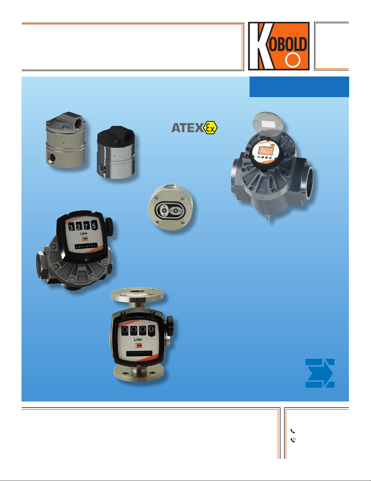
Oval Gear Flowmeter
for Low and High Viscosity Liquids
measuring
•
monitoring
•
analyzing
DON
●● Measuring Range:
0.13 … 9.5 GPH to 40 … 660 GPM
●● Viscosity Range: up to 1000 cP
(Higher upon Request)
●● Accuracy: ± 0.2% …1% of Reading
●● Material: Aluminum or Stainless Steel
●● p
: 1450 PSI; t
max
●● Pulse Output, LCD Display, 4…20 mA,
max
Alarms, Mechanical Totalizer
KOBOLD companies worldwide:
ARGENTINA, AUSTRALIA, AUSTRIA, BELGIUM, BULGARIA, CANADA, CHILE, CHINA, COLOMBIA,
CZECH REPUBLIC, EGYPT, FRANCE, GERMANY, HUNGARY, INDIA, INDONESIA, ITALY, MALAYSIA,
MEXICO, NETHERLANDS, PERU, POLAND, REPUBLIC OF KOREA, ROMANIA, SINGAPORE, SPAIN,
SWITZERLAND, TAIWAN, THAILAND, TUNISIA, TURKEY, UNITED KINGDOM, USA, VIETNAM
05/07-30-2019
: 300 °F
KOBOLD Instruments, Inc.
1801 Parkway View Drive
Pittsburgh, PA 15205
Main Ofce:
1.800.998.1020
1.412.788.4890
info@koboldusa.com
www.koboldusa.com
Page 2
Oval Gear Flowmeter Model DON
Description
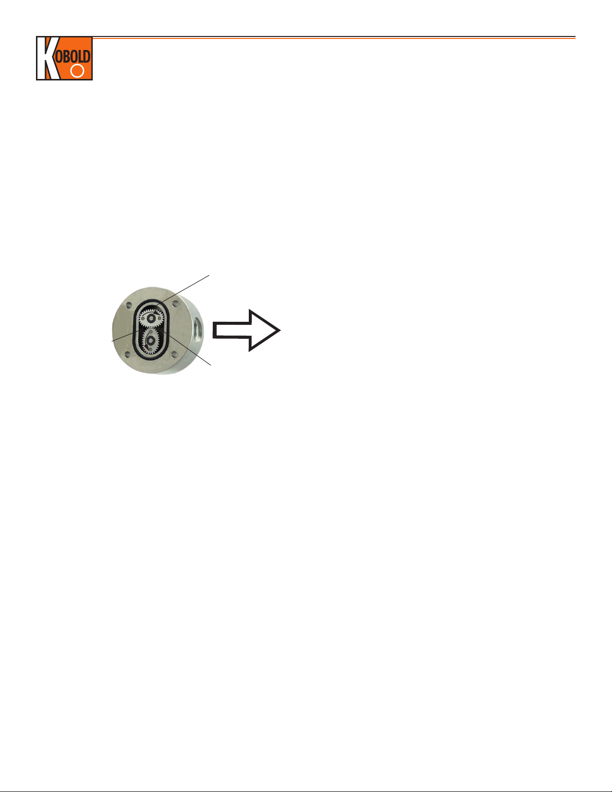
Oval gear flowmeters are categorized as positive displacement
flow technology. When liquid flows through this type of positive
displacement flowmeter, two oval geared rotors measure a constant
volume per rotation within a precisely machined measuring chamber.
With each rotation, a constant volume of liquid is measured. The
rotation of the oval gears is sensed via magnets embedded within
the rotors. These magnets transmit a high resolution pulse output.
The output signal can be processed externally via a remote display
controller or PLC or via a variety of output/display options available
as accessories attached to the flowmeters.
Operation:
Liquid travels around
the crescent shaped
chambers created by
the rotational movement
of the rotors
Liquid in transit
Flow
Liquid entering the
measuring chamber
The positive displacement flow technology allows for precise flow
measurement of most clean liquids regardless of the media's
conductivity. Other liquid properties also have a minimal effect on
the performance of this type of meter. Flow profile conditioning is
not required, as with alternative flow technology options, making
oval gear installations simple to install in tight spaces and at a
economical price.
Areas of Application
Suitable for viscous, non abrasive, clean liquids like:
Petroleum
Grease
Pastes
●
●
Oil
Fuels
●
●
Aluminum body meters are compatible with fuels, fuel oils, & other
lubricating liquids. In addition to lubricating media, stainless steel
flowmeters are suitable for most products and chemicals.
Technical Data
Materials
DON-1
Body: Aluminum
Gears: PPS GF 30 / PTFE
Axles: 316L Stainless Steel
DON-2
Body
DON-x05 ... DON-x15: 316L Stainless Steel
(DON-205 Body Cover is 316LN SS)
DON-x20 ... DON-x60: 316L/301* Stainless Steel
2
Liquid exits
the measuring
chamber
Chemicals
Ink
www.koboldusa.com
Gears
DON-x05 ... DON-x40: 316L Stainless Steel
DON-x45 ... DON-x60: 301* Stainless Steel
Bearing: Carbon Graphite
Axles: 316L Stainless Steel
DON-8
Body
DON-x05 ... DON-x15: 316L Stainless Steel
(DON-805 Body Cover is 316LN SS)
DON-x20 ... DON-x60: 316L/301* Stainless Steel
Gears: PPS GF 30 / PTFE
Axles: 316L Stainless Steel
O-Rings (Media Temperature Limits)
FKM: -4 ... 300 °F
NBR: -4 ... 212 °F
FEP-Clad EPDM: 5... 266 °F
Electrical Cover (for Cable Connection)
Standard: Polyamide PA6 GF35 UL94 HB/VO
Optional: 316L Stainless Steel
Cable Entry: M 20 x 1.5 or ½" NPT Adapter
Screw Material
for Aluminum Housing: Stainless Steel (Standard)
Steel Coated with GEOMET® 321
(for DON-225 and DON-825)
for Stainless Steel
Housing: Stainless Steel (Standard)
Steel Coated with GEOMET®321
(optional) for Higher Pressure Rating
(See Order Details)
Accuracy**
DON-x05...DON-x15: ± 1% of Reading
DON-x20...DON-x60
SS Rotors: ± 0.5% of Reading; ± 0.2% of Reading
with Optional Z3/E3 Electronics with
Linearization Function
PPS Rotors: ± 1% of Reading; ± 0.5% of Reading
with Optional Z3/E3 Electronics with
Linearization Function
Option M4: ± 1% of Reading
Additional Inaccuracy
for Analog Outputs: ± 0.15% of Full Scale
(Better Accuracies for Higher Viscosities Available upon Request)
Repeatability: ± 0.03 % Typical
Protection Class: IP 66/67 (IP 65 for M4)
Media Temperature
Options ..Lx, ..Zx, ..M4: -4...176 °F
DON-1/DON-8 Max: 176 °F (PPS Rotors)
Pulse Out or Option ..Zx
with Cooling Fins: -4...250 °F
Option ..T0: -4...300 °F
Ambient Temperature -4 ... 176 °F,
Option M4: 32...140 °F
Cable Entry: M20 x 1.5 or 1/2" NPT Adapter
* Closest AISI Equivalent to 1.3955 Stainless Steel
** Reference Conditions: DON-x05...x20 (Mineral Oil, 10 cSt, 68 °F, 75 PSIG)
DON-x25...x60 (Mineral Oil, 3 cSt, 68 °F, 14 PSIG)
Accuracy data is valid for given viscosities and higher
No responsibility taken for errors;
subject to change without prior notice.
Page 3
Oval Gear Flowmeter Model DON
ATEX-Approval
(Options E1/E2/E3/E4/E5): II 2G Ex ia IIC T4 Gb (-20 °C ≤ Ta ≤ +60 °C)
(Options HE, DE, BE,
KE, GE, LE, RE): II 2G Ex db IIC T4/T6 Gb
I M2 Ex db I Mb
IECEx-Approval
(Options E1/E2/E3/E4/E5): Ex ia llC T4 Gb
(Options HE, DE, BE, KE,
GE, LE, RE): Ex db llC, Ex db l Mb
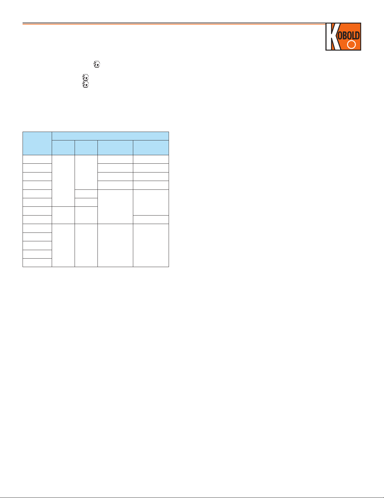
Maximum Pressure (Threaded Models)
Maximum Pressure (PSI)
Model
DON-x05
DON-x06 - -
DON-x10 - -
DON-x15 - -
DON-x20 1000*
DON-x30
DON-x35 435
DON-x40
DON-x45
DON-x50
DON-x55
DON-x60
With flanges: Maximum pressure rating as above or as per flange rating,
whichever is lower.
* Max pressure of 1450 psi possible with steel screws (see order details)
DON-1
925
580 725
230 230 230 230
DON-
2/8
1450
DON-1 (Op-
tion-M4)
- -
580
DON-2/8
(Option–M4)
580DON-x25 870*
Output Types
Reed Switch Pulse Output (.. R0 / RE)
The reed switch output is a two wire, normally open, SPST, voltage
free contact ideal for installations without power or for use in
hazardous area locations where Intrinsically Safe (I.S.) is required.
Note: when using the reed switch output, the liquid temperature must
not change at a rate greater than 18 °F per minute.
Average switching life of reed contact (MTTF):
Max. Load (100 V / 10 mA) 5 x 10⁵ switching cycles
Min. Load (<5 V / 10 mA) 5 x 10⁸ switching cycles
Power supply: max. 30 VDC, max. 200 mA
Hall Sensor Pulse Output (.. H0/HE)
In the electronics options H0/HE, a Hall Effect sensor is combined
with an active push-pull output. The signal output is actively switched
either to +Vs or to ground. No additional external circuit is required
(e.g. pull-up resistor). The "high" signal is approximately equal to the
supply voltage +Vs and the "low" signal is approximately 0 V. The
electronic utilizes a 3-wire connection with an external supply voltage
of 8 ... 30 VDC. The electrical load may be optionally connected to
the supply voltage or to GND. Maximum output current (current
source or sink): 100 mA (short circuit protected). In addition to the
Hall sensor, this option is equipped with a Reed switch which works
the same as option R0/RE.
No responsibility taken for errors;
subject to change without prior notice.
www.koboldusa.com
Hall Sensor Pulse Output (.. HU)
Like option H0, except an NPN output in place of the
push-pull output and a supply voltage of 5-30 V
DC.
Hall Sensor Pulse Output, (.. B0/BE)
Like options H0/HE; however with bipolar sensors and
alternating polarized magnets. This option is used for
pulsating flow, but is not equipped with a Reed switch and
has half the k-factor value as compared to H0/HE.
High-Resolution Hall Sensor Pulse Output, (..G0/GE,
..K0/KE)
Like options H0/HE; the models DON-x05 and DON-x10 can
be supplied with four times the pulse count per volume unit
and models DON-x05...x20 with double the amount of pulses
(K0/KE) (see table «Output Pulse Resolution» on the following
pages).
Quadrature Hall Effect Pulse Output (..D0/DE)
The DON with option D0/DE provides two independent Hall
sensors. They are arranged to give separate outputs out of
phase with one another.
The QUAD output is mostly suitable for detecting bidirectional
flows (detection of flow direction) or where a redundant signal
is desirable. Maximum output current per channel (current
source or sink): 100 mA (short circuit protected).
Analog Output (..L0/LE)
The options L0 and LE (Ex) are available with a loop-powered
4-20 mA output. The loop must be powered with an external,
16...32 VDC power supply. The maximum resistance of the
series loads (PLC analog input / display electronics) depends
on the magnitude of the supply voltage and can be calculated
as follows:
Max. load [Ohm] = (+Vs – 9 VDC) / 0.02 A [Ω]
Example: +Vs = 32 VDC = > max. load = 1150 Ω
+Vs = 16 VDC => max. load = 350 Ω
The load can be inserted at any point in the current loop,
observing correct polarity.
Mechanical Totalizer (..M4)
The DON-x20 .. through DON-x60 .. are available with a 4-digit
resettable totalizer and indication of accumulated total value.
The motion of the rotors is transmitted to the mechanical
register totalizer via an interfacing reduction gear train and
dynamic seal assembly. Option M4 is also optionally available
in liters.
Body Material: Enameled Die-cast Aluminum,
Powder-coated
Protection: IP 65
Ambient Temp: 32...140 °F
Media Temp: -4...176 °F
Recommended Filtration Requirements:
DON-x05 ... DON-x15 < 75 μm (200 mesh)
DON-x20 ... DON-x35 < 150 μm (100 mesh)
DON-x40 ... DON-x60 < 350 μm (45 mesh)
3
Page 4

Electronic with LCD Display
Model ..Z1 ..Z2 ..Z3 ..ZE ..ZB ..E1 ..E2 ..E3 ..E4 ..E5
Oval Gear Flowmeter Model DON
Function
Dual
Totalizer
Batching
Unit
Rate/Totalizer
Dual
Totalizer
Batching Unit Rate /Totalizer Rate /Totalizer Rate /Totalizer
Power Supply
External
(also for Backlighting)
Battery-Operation
(Outputs Inactive)
Battery Included
in Shipment
2)
3)
5 - 28 VDC12 - 28 VDC5 - 28 VDC9 - 28 V
DC
-
yes no yes yes yes yes no yes no no
yes
-
yes no yes yes
-
Ui = 28 V
Ii = 100 mA
Pi = 0.7 W
yes
- -
LCD Display
Selectable Units yes yes yes yes yes yes yes yes yes yes
Decimal Point yes yes yes yes yes yes yes yes yes yes
Accumulative Total yes yes yes yes yes yes yes yes yes yes
Resettable Total yes yes yes yes yes yes yes yes yes yes
Linearization yes no yes yes yes yes no yes yes yes
Rate Display yes yes yes yes yes yes yes yes yes yes
Backlighting yes yes yes yes no no no no no no
Input
Sensors Hall Sensor/Reed Switch Reed Switch
Outputs
4-20 mA no no yes no no no no yes yes (HART®) yes
Flow Rate
Alarm Min./Max.
no
no
NPN/PNP/
Push-Pull
no no no no no no
optocoupler
Batch End & Control no yes no no no no yes no no no
Pulse Output no no Push-Pull Push-Pull no no no no no
2 x SPDT Relays
1)
no yes option no no no
with
optocoupler
no no
optocoupler
Installation
IP 65 yes yes yes IP 66/67 IP 66/67 yes yes yes yes yes
with
with
Cable Entries M20x1.5 or ½" NPT
Media Temperature
Range
(Cooling Fin Option: max.
250 °F)
Ambient Temperature
Range
-4... 176 °F 32 ... 140 °F
-4...176 °F
Housing Material PA6 GF35 UL94 HB/VO / PC UL94 V-2
ATEX Approval no yes
1)
Replaces solid state outputs, for details see ZOK Datasheet
2)
Battery operation only acceptable with reed switch sensor "Rx"
3)
Options Z6, Z7, Z8, and Z9 are shipped without batteries
4
www.koboldusa.com
No responsibility taken for errors;
subject to change without prior notice.
Page 5

DON Pressure Drop Versus Viscosity Curves
Oval Gear Flowmeter Model DON
1 Standard Rotors 100 % of Full Scale
2 Standard Rotors 50 % of Full Scale
Special Cut Rotors 100 % of Full Scale
3 Standard Rotors 25 % of Full Scale
Special Cut Rotors 50 % of Full Scale
4 Special Rotors 25 % of Full Scale
5 Special Rotors 10 % of Full Scale
2 Standard Rotors 50 % of Full Scale
Special Cut Rotors 100 % of Full Scale
3 Standard Rotors 25 % of Full Scale
Special Cut Rotors 50 % of Full Scale
4 Special Cut Rotors 25 % of Full Scale
5 Special Cut Rotors 10 % of Full Scale
6 Special Cut Rotors 5 % of Full Scale
Pressure Drop Limit Versus Flowrate
The curves above represent the pressure drop for standard cut oval rotors. Special cut rotors, option "Y" have alternate tooth relief
which effectively reduces the pressure drop by 50%. When sizing a meter, be sure your selection falls below the 1 bar (14.5 PSI)
maximum allowable pressure drop line on the graph.
No responsibility taken for errors;
subject to change without prior notice.
www.koboldusa.com
5
Page 6

Oval Gear Flowmeter Model DON
Maximum Flowrate Multiplier (for Higher Viscosities)
Viscosity
(cPs)
≤ 1,000 1 1
≤ 2,000 0.5 1
≤ 4,000 0.42 0.84
≤ 6,000 0.33 0.66
≤ 8,000 0.25 0.5
≤ 30,000 0.15 0.3
≤ 60,000 0.12 0.25
≤ 150,000 0.1 0.2
≤ 250,000 0.05 0.1
≤ 1,000,000 0.025 0.05
Standard
Rotor
Special Cut
Rotor
Special Cut Rotors for Higher Viscosities
For viscosities > 1000 cP, special cut rotors (option: "Y") are
normally required to keep the maximum pressure drop from
exceeding acceptable levels. This option applies to DON-x15
and larger sizes. For higher viscosities, the flowmeter max.
flowrate is derated according to the table above.
Example:
DON-x25G measuring viscous oil at 8000 cP:
max. flow of 40 GPM x 0.5 = 20.0 GPM new max. flow rate.
Noise Level (in dB) at Full Scale
Size PPS Gears SS Gears
x25 83 91
x30 84 93.1
x35 83.5 95
x40 85.4 96
x45 87.5 98
x50 86.1 99.4
x55 86.1 98.1
x60 85 99
Information Required for Order:
To ensure proper operation, this product requires a
completed application guide form to be submitted with
any order. Please refer to the ‘documentation’ tab on
the bottom of the product page for this product on our
website in order to obtain the correct form. You can
also contact your KOBOLD representative for this form.
Nominal Output Pulse Resolution*
Model
DON-x05 0.13...9.5 GPH 10107 10107
DON-x06 0.5...9.5 GPH 10107 10107
DON-x10 0.5...27 GPH 4020 4020
DON-x15 4...145 GPH 1329 2657
DON-x20 0.26...10.6 310 617
DON-x25 2.6...40 98 394
DON-x30 4.0...66 51 208
DON-x35 8.0...120 24.2 96.5
DON-x40 13...150 18.5 74.2
DON-x45 10...200 9.7 39.0
DON-x50 13...260 5.7 22.3
DON-x55 20...400 3.97 15.9
DON-x60 40...660 2.12 8.71
Flow Range
(GPM)
Reed Switch
Rx
Hall Sensor
Hx
Pulse per Gallon
Hall Sensor
Bx
---
---
---
1329
310
98
51
24.2
18.5
9.7
5.7
3.97
2.12
QuadratureHall Sensor
Dx
10107 42851 20214
- - -
4020 16080 8040
2657 --- 5315
617 --- ---
197 --- ---
102 --- ---
51.1 --- ---
37.1 --- ---
19.5 --- ---
11.4 --- ---
7.95 --- ---
4.35 --- ---
Hall Sensor,
High-Resolution
Gx
*The output resolution values listed in the above table are only approximate values. The exact output resolution value is
noted within the calibration certificate delivered with each flowmeter.
Hall Sensor,
High-Resolution
Kx
6
www.koboldusa.com
No responsibility taken for errors;
subject to change without prior notice.
Page 7

Oval Gear Flowmeter Model DON
Order Details (Example: DON-105G N1 1 L0 N 0)
Housing / Rotor Material
Measuring
Range
0.13...9.5
GPH
0.5...9.5
GPH
0.5...27
GPH
4...145
GPH
0.26...10.6
GPM
2.6...40
GPM
4.0...66
GPM
8.0...120
GPM
13...150
GPM
10...200
GPM
13...260
GPM
20...400
GPM
40...660
GPM
1)
Only for DON-x35; 2) Only for DON-x05 and DON-x10; 3) Without Backlighting; 4) Replace 'G' with 'H' to Order LPM (LPH); 5) With Steel Screws, Only for DON-2... and
DON-8...;
Ordering, (Possible Flow Directions: Bottom to Top, Left to Right, or Right to Left);
9)
Only for DON-x05, -x10, -x15 Without Reed Switch;
Aluminum
with PPS
Rotor
Stainless
Steel
DON-105G.. - -
- DON-206G.. DON-806G..
DON-110G.. DON-210G.. DON-810G..
DON-115G.. DON-215G.. DON-815G..
DON-120G.. DON-220G.. DON-820G..
DON-125G.. DON-225G.. DON-825G..
DON-130G.. DON-230G.. DON-830G..
DON-135G.. DON-235G.. DON-835G..
DON-140G.. DON-240G.. DON-840G..
DON-145G.. DON-245G.. DON-845G..
DON-150G.. DON-250G.. DON-850G..
DON-155G.. DON-255G.. DON-855G..
DON-160G.. DON-260G.. DON-860G..
10)
6)
Only for DON-x20...DON-x60; see M4 Option Description for Details on Minimum Incremental Volume Unit per Model Number; Please Specify Flow Direction when
Option(s) to Add. Special Cut Rotors for Higher Viscosities: Not for DON-x05...DON-x10, Check Valve: From DON-x30..., and any other Non-Standard Request
No responsibility taken for errors;
subject to change without prior notice.
4)
Stainless
Steel with
Connection
O-ring
Material
PPS Rotor
..N1.. = ⅛
" NPT
..R1.. = G ⅛
..N1.. = ⅛
" NPT
..R1.. = G ⅛
N2.. =
..
..R2.. =
..N3.. = ⅜
¼" NPT
G ¼
" NPT
..R3.. = G ⅜
N4.. =
..
..R4.. =
P45).. =
..
..H45).. =
N6.. =
..
..R6.. =
A6.. =
..
½" NPT
G ½
½" NPT (1450 psi)
G ½ (1450 psi)
1" NPT
G 1
1" 150 lb
ANSI Flange
B6.. =
..
1" 300 lb
ANSI Flange
F6.. =
..
DN25 PN40
DIN Flange
P65).. =
..
..H65).. =
N8.. =
..
..R8.. =
A8.. =
..
ANSI Flange
B8.. =
..
ANSI Flange
F8.. =
..
1" NPT (1450 psi)
G 1 (1450 psi)
1½" NPT
G 1½
1½" 150 lb
1½" 300 lb
DN40 PN40
..1.. = FKM
..3.. = FEP
Coated
EPDM
..4.. = NBR
DIN Flange
N9.. =
..
..R9.. =
A9.. =
..
2" NPT
G 2
2" 150 lb
ANSI Flange
B91).. =
..
2" 300 lb
ANSI Flange
F9.. =
..
DN50 PN16
DIN Flange
..C9.. = DN50 PN40
DIN Flange
NB.. =
..
..RB.. =
AB.. =
..
3" NPT
G 3
3" 150 lb
ANSI Flange
FB.. =
..
DN80 PN16
DIN Flange
NC.. =
..
..RC.. =
AC.. =
..
4" NPT
G 4
4" 150 lb
ANSI Flange
FC.. =
..
DN100 PN16
DIN Flange
7)
10)
Calibrated up to 500 GPM. Higher Flow Rate Calibration on Request;
Only for Electronic Options -Zx/-Ex, not for DON-1.. and DON-8..; 8) Only for DON-2;
www.koboldusa.com
Electronic/ Display Cable Entry Option
..R0..
= Reed Switch Pulse
Output
..RE..
= Reed Switch Pulse
Output ATEX (Exd)
.H0.. = Hall Sensor (Push-Pull) /
Reed Switch Pulse
Output
..HE..
= as H0 + ATEX
..HU..
= NPN Pulse Output
(Hall / Reed),5-30 V
DC
..B03).. = For Pulsating Flow
..BE3).. = B0 + ATEX (Exd)
..K09).. = High Resolution Hall
Sensor (x2)(Push-Pull)
..KE9).. = as K0 + ATEX (Exd)
..G02).. = High Resolution Hall
Sensor (x4)(Push-Pull)
..GE2).. = as G0 + ATEX (Exd)
11)
..D0
.. = Quad. Hall Sensor
..M.. = M20
2 Phased Outputs
(Push-Pull)
11)..
..DE
= as D0 + ATEX (Exd)
..N.. = ½" NPT
..L0.. = 4 ... 20 mA Loop
Powered Analog Output
..LE.. = as L0 + ATEX (Exd)
..T08).. = Hall Sensor (Push-Pull) /
High-Temp 300 °F Max.
..S7).. = M20
with
Cooling
Fin
..Z1.. = Dual LCD Totalizer
(ZOK-Z1)
..Z2.. = Batching Unit LCD
(ZOK-Z2)
..Z3.. = LCD Totalizer, Rate,
Outputs: 4-20 mA, Alarm,
Pulse (ZOK-Z3) (Impulses
..T7).. = ½" NPT
with
Cooling
Fin
not for Battery Supply)
..Z6.. = Z1 + B0
..Z7.. = Z3 + B0
..Z8.. = Z1 + D0
..Z9.. = Z3 + D0
..ZE.. = LCD Rate / Total
(ZOE with External
Supply / with Battery)
..ZB3).. = LCD Rate / Total (ZOE
Without External Supply /
with Battery)
..E13).. = as Z1 + ATEX/IECEx (Exi)
..E23).. = as Z2 + ATEX/IECEx (Exi)
..E33).. = as Z3 + ATEX/IECEx (Exi)
(Without Switching or
Pulse Outputs)
..E43).. = E3 + HART
®
..E53).. = E3 + Pulse or Switching
Outputs with 4-20 mA
..M46).. = Mechanical Totalizer,
4-Digit
11)
Not for DON-x06;
..0.. = Without
12)
Specify in Writing which
..0 = Without
12)
..Y
= Special
Request
7
Page 8

42,4
13
115
6,5
21,6
61
42,4
13
115
6,5
42,4
13
6,5
Dimensions DON-1(2/8)...
DON-x05...DON-x15
Mounting Surface
Oval Gear Flowmeter Model DON
DON-x45...DON-x60
Pulse Output
Zx/Ex
Zx/Ex with
Cooling Fin
Mech. Totalizer M4
2.0"
Pulse Output
Zx/Ex
DON-x20...DON-x40
Zx/Ex with
Pulse Output
Zx/Ex
Cooling Fin
Zx/Ex with
Cooling Fin
Mech. Totalizer
M4
B
Electronic with LCD Display Zx / Ex
0.9"
21,6
2.4"
0.9"
61
2.4"
52
2.1"
0.9"
with optional Cooling Fins
32
Dimensions* DON-1(2/8)… (± 0.08")
1.3"
2.6"
66
131
5.2"
134
5.3"
A B C
Model
Thread
Connection
Flange
Connection
Pulse Output Zx/Ex
Mechanical
Totalizer M4
Pulse
Output/Lx
Zx/Ex
DON-x05 2.67" - 3.62" 5.16" - 2.83" 5.28" -
DON-x06 (2.67") - (3.62") (5.16") - (2.83") (5.28") -
DON-x10 2.67" - 3.62" 5.16" - 2.83" 5.28" -
DON-x15 2.67" - 3.89" 5.43" - 2.83" 5.28" -
DON-x20 4.33" - 4.13" (3.98") 5.28" (5.12") 7.17" (7.01") 4.41" 5.28" 6.50"
DON-x25 6.93" 9.33" 5.36" 6.50" 7.64" 4.72" 5.28" 6.69"
DON-x30 7.40" 9.92" 6.54" 7.68" 8.78" 6.42" 6.42" 7.88"
DON-x35 8.34" 10.90" 6.77" 7.92" 9.61" 7.09" 7.09" 7.88"
DON-x40 8.34" 10.90" 9.69" 10.83" 11.77" 7.09" 7.09" 7.88"
DON-x45 10.50" 13.90" 9.13" 10.28" 11.18" 9.37" 9.37" 9.41"
DON-x50 11.60" 15.00" 9.02" 10.16" 11.89" 11.41" 11.41" 11.41"
DON-x55 11.60" 15.30" 10.80" 11.93" 13.66" 11.41" 11.41" 11.41"
DON-x60 12.60" 16.30" 13.80" 14.96" 16.70" 13.03" 13.03" 13.03"
*
Dimensions for DON-2/8... are specified in ( ) only when they are different from DON-1...
8
www.koboldusa.com
Mechanical
Totalizer M4
No responsibility taken for errors;
subject to change without prior notice.
 Loading...