

Page 1

Operating Instructions
for
Oscillation Flowmeter
Model: DOG-4...
Transducer and Electronic Options A/B…O/P
Page 2

DOG-4
page 2 DOG-4 K08/0818
1. Contents
1. Contents ....................................................................................................... 2
2. Note .............................................................................................................. 4
3. Information on operating the device in potentially explosive environments
(Ex, A0/D0/F0/H0/K0/N0/P0 option) ........................................................... 4
3.1 General requirements .......................................................................... 5
3.2 Startup, installation .............................................................................. 6
3.3 Application ........................................................................................... 6
3.4 Repair, maintenance (for applications in Ex areas) ............................. 7
3.1 Disposal .............................................................................................. 7
4. Instrument Inspection ................................................................................... 8
5. Regulation Use ............................................................................................. 8
6. Operating Principle ....................................................................................... 9
7. Mechanical Connection .............................................................................. 10
8. Identification (Ex version) ........................................................................... 11
9. Electrical connections ................................................................................. 12
9.1 General ............................................................................................. 12
9.2 Measuring cable in Ex areas ............................................................. 12
9.3 Connection to the measuring sensor ................................................. 12
9.4 Terminal assignment of the DOG-4… reader/transducer .................. 13
9.5 Terminal assignment of the electronic option
G0/H0/I0/K0/M0/N0/O0/P0 ................................................................ 15
9.6 Connections of DOG-4 Transmitter with KOBOLD Evaluation
Electronics ZED-X and ZOK-Zx ......................................................... 17
10.Startup ........................................................................................................ 20
11.Setup and operation of the flow controller/flow computer (option
G0/H0/I0/K0/M0/N0/L0/O0/P0) ................................................................ 20
12.Transmitter error message ......................................................................... 21
12.1 Status display not illuminated ............................................................ 21
12.2 OPERATING illuminated green but no output signal ......................... 21
12.3 RANGE illuminated yellow................................................................. 21
12.4 ERROR illuminated red ..................................................................... 21
13.Maintenance ............................................................................................... 22
13.1 Replacing the sensor ......................................................................... 22
13.2 Disassembly and cleaning the Flowmeter ......................................... 22
14.Technical Data ............................................................................................ 24
14.1 Electronic options .............................................................................. 25
15.Order Details .............................................................................................. 29
16.Pressure Loss/Flow .................................................................................... 31
17.Dimensions ................................................................................................. 32
18.EU Declaration of Conformance ................................................................. 34
19.ATEX-Certificate ......................................................................................... 35
20.IECEx-Certificate ........................................................................................ 41
Page 3

DOG-4
DOG-4 K08/0818 page 3
Manufactured and sold by:
Kobold Messring GmbH
Nordring 22-24
D-65719 Hofheim
Tel.: +49(0)6192-2990
Fax: +49(0)6192-23398
E-Mail: info.de@kobold.com
Internet: www.kobold.com
Page 4
DOG-4
page 4 DOG-4 K08/0818
2. Note
Please read these operating instructions before unpacking and putting the unit into
operation. Follow the instructions precisely as described herein.
The devices are only to be used, maintained and serviced by persons familiar with
these operating instructions and in accordance with local regulations applying to
Health & Safety and prevention of accidents.
as per machine-guidelines 2006/42/EC
CE mark acc. ATEX-guideline 2014/34/EU
When used in machines, the DOG-4 should be used only when the machines fulfil
the EC-machine guidelines.
as per PED 2014/68/EU
Model Connection PN
no dangerous gases
(diagr. 7, 2)
dangerous gases
(diagr. 6, 1)
DOG-4
DN 25 10 article 4, § 3 I
DN 40 until DN 50 10 I II
DN 80 until DN 150 10 I II
DN 200 10 I II
Funded by the Federal Ministry of Economics and Technology based on a decision
of the German Bundestag.
3. Information on operating the device in potentially
explosive environments (Ex, A0/D0/F0/H0/K0/N0/P0
option)
The devices can be used in the following way:
1. DOG-4S Flowmeter: In zones 0, 1 and 2 (gas Ex, category 1G, 2G, 3G) in
explosion groups IIA, IIB and IIC
2. DOG-4A Reader/Transducer Reader: Outside the EX area
Here the following ambient temperatures must be adhered to
-20 °C ≤ Ta ≤ 60 °C
The DOG-4 is suitable for use with gases of the explosion group IIC and temperature
class ≥ T4.
Further important details can be found in the EC Type Examination Certificate.
Page 5

DOG-4
DOG-4 K08/0818 page 5
3.1 General requirements
In the event of failure to comply with this information or unauthorized tampering with
the device, the manufacturer's liability will no longer apply. Moreover, the guarantee
for the device and accessory parts will become void.
Comply with the information in these operating instructions and adhere to the
conditions of use and permissible data printed on each device / type plates.
Follow the generally accepted rules of technology when selecting and
operating a device.
Take appropriate measures to prevent unintentional activation or inadmissible
impairments.
The devices may be used only in the correct way and for the intended
purpose in a normal industrial environment. Use for unsuitable purposes, will
render all guarantees and liability of the manufacturer void!
Ensure that only devices with ignition protection suitable for the operating
zones are installed.
All electronic operating resources connected must be suitable for the
respective use.
The operator is obligated to provide lightning protection according to local
regulations.
Page 6

DOG-4
page 6 DOG-4 K08/0818
3.2 Startup, installation
The devices are intended for installation in a higher-level system. The intervals for
cleaning the operating resources (dust deposits) are specified depending on the
degree of IP protection. It is extremely important to ensure that only devices with
suitable ignition protection for the zones/categories are installed! It is essential that
the installation regulations applicable at the national level, e.g. EN 60079-14, are
adhered to during installation. Other important factors:
In the event of adverse environmental conditions, it is necessary to ensure
that the devices are accordingly protected.
Follow the operating instructions for the respective device and adhere to any
special conditions described there.
The device may only be used for the purpose for which it was intended.
It is essential to avoid electrostatic charges.
Any possible metal parts in the device/lines (e.g. shielding) must be
incorporated in the potential equalization PA in compliance with the user’s
country regulations.
Parts that have jammed (e.g. as the result of frost or corrosion) may not be
loosened by force in hazardous atmospheres.
Operate the device only in the completely assembled state and enclosed in
undamaged housing. Operating with a damaged housing is prohibited.
At ambient temperatures of less than -5°C the connecting lines must be
securely laid.
Do not allow the outside of the device to come into contact with strongly
corrosive media.
Do not subject the system to excessive vibrations, bending or torsion.
The devices may not – or only with the manufacturer's permission, and then
only using special measures – be used in systems with electric corrosion
protection. Parasitic currents must not be fed in via the shielding.
Installations in Ex areas may be carried out only in compliance with the local
installation regulations.
Installation and maintenance only in ex-free atmospheres in compliance with
the user’s national regulations.
Additional precautionary measures must be taken if there is a possibility that
hydrogen sulfide, ethylene oxide and/or carbon monoxide could be present. These
compounds have very low ignition power!
Only non-arcing tools may be used for these compounds as well as all compounds
included in explosion group IIC – if explosive atmospheres are still to be expected!
3.3 Application
The devices may be used only in the correct way and for the intended purpose in a
normal industrial environment. Use for unsuitable purposes, will render all
guarantees and liability of the manufacturer void!
See Chapter 4, 5, 7 and 9.
Page 7

DOG-4
DOG-4 K08/0818 page 7
3.4 Repair, maintenance (for applications in Ex areas)
Definition of terms as defined in IEC 60079-17:
Repair and maintenance: A combination of all activities carried out to maintain an
item or restore the object to a state in which it is able to meet the requirements of the
relevant specification and ensure the execution of its required functions.
Inspection: An activity comprising the careful examination of an item carried out
either without demounting or, if necessary, with partial demounting through such
steps as measurement in order to reliably determines the condition of the item.
Visual inspection: An inspection in which visible faults, e.g. missing bolts, are
detected without the use of equipment or tools.
Close inspection An inspection which comprises the aspects of a visual inspection
in addition to identifying defects, e.g. loose bolts, apparent only by access with the
use of equipment, e.g. steps (when necessary) and tools. Close inspections do not
normally require an open enclosure or the de-energizing of the equipment.
Detailed inspection An inspection which encompasses those aspects covered by a
close inspection and, in addition, identifies those defects, e.g. loose connections
which are only be apparent by opening the enclosure and/or using tools and test
equipment where necessary.
Maintenance work may be performed only by qualified personnel with the
equivalent of or qualification according to TRBS 1203 (German Technical
Rules for Industrial Safety).
Only accessory parts which fulfill all European regulations and national laws
may be used in hazardous areas.
The replacement of components may only take place using original spare
parts approved for use in Ex areas as well.
The devices in Ex areas must be cleaned regularly. The intervals must be
specified by the operator according to the environmental load.
After maintenance and/or repair, replace all barriers and notices removed in
the process in their original positions.
Uninstall the device if any faults are detected. The customer may not repair
internal parts. Send the device to the manufacturer for inspection.
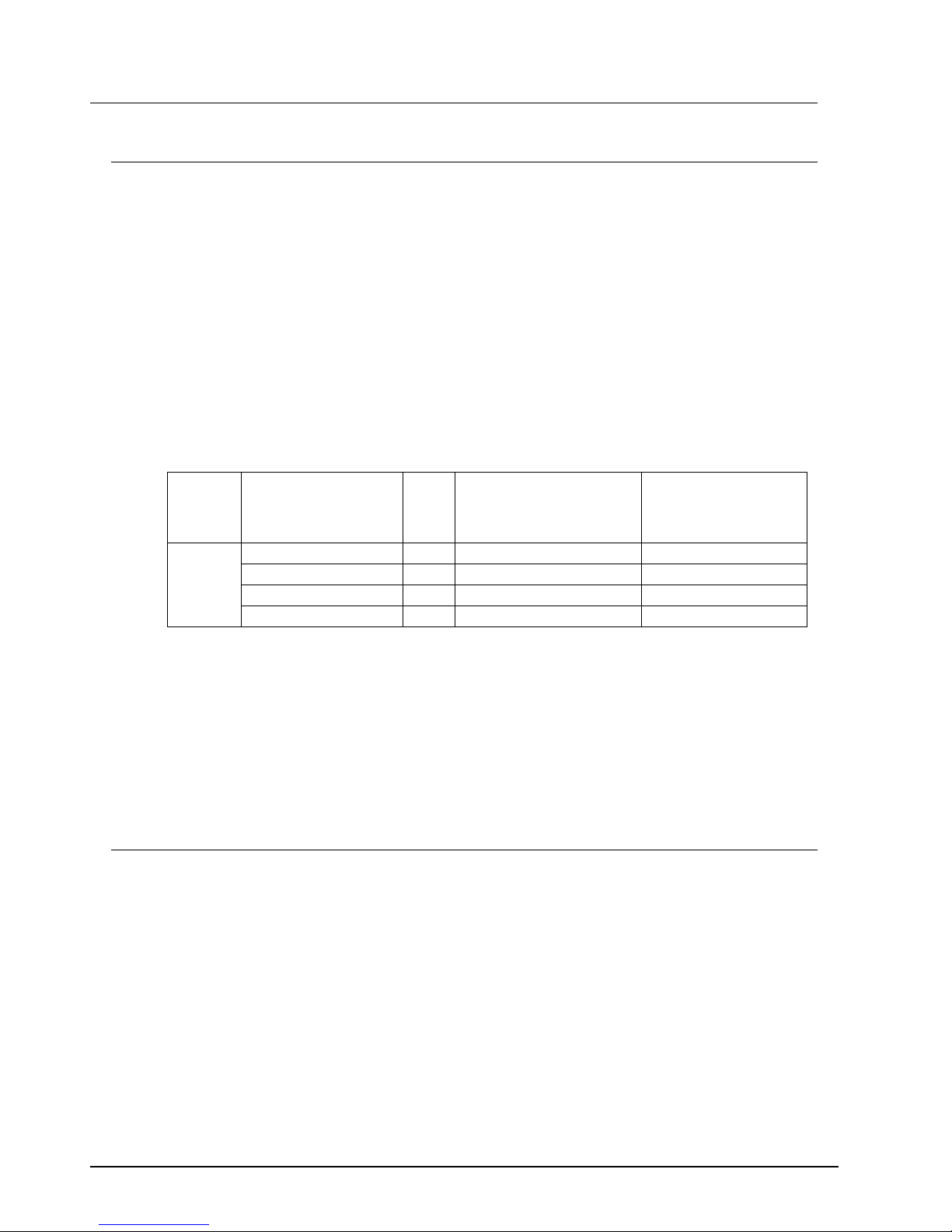
Task
Visual inspection
monthly
Check
every 6 months
Detailed inspection
every 12 months
Visual inspection of the device for
integrity, remove dust residues
● ●
Inspection of the entire system Responsibility of the operator
3.1 Disposal
Disposal of the packaging and the used parts must be carried out according to the
regulations of the country in which the device is installed.
Page 8

DOG-4
page 8 DOG-4 K08/0818
4. Instrument Inspection
Instruments are inspected before shipping and sent out in perfect condition.
Should damage to a device be visible, we recommend a thorough inspection of the
delivery packaging. In case of damage, please inform your parcel service /
forwarding agent immediately, since they are responsible for damages during transit.
Scope of delivery:
The standard delivery includes:
DOG-4S Flowmeter including flange housing, measuring head, thermal wire
sensor and connection box.
Measuring cable from the Flowmeter to the measuring converter (optional).
DOG-4A/B…O/P reader/transducer.
Operating instructions.
5. Regulation Use
DOG-4 type devices are used for measuring and monitoring the rate of flow. Only
clean media may be measured, against which the materials used are resistant. Dirt
particles and other impurities can impair the measurement results, in spite of the fact
that the continuous change in direction of the flow ensures a self-cleaning effect. The
measuring sensor may be used only with the corresponding transducer.
Connectioon box
Measuring cable
Reader/
Transducer
Flowmeter
Flange housing
Measuring head
Direction
Page 9

DOG-4
DOG-4 K08/0818 page 9
6. Operating Principle
This device is a oscillating beam device and works without any movable parts. An
orifice plate in the base creates flow resistance, which forces a partial flow to be
directed into the measurement head. The gas in the measuring head begins to
oscillate. The frequency of oscillation is proportional to the flow of volume. As the
ratio between the flow through the measuring head and the flow through the
measuring housing is constant, the frequency of oscillation is directly proportional to
the entire flow of volume through the device. A platinum sensor determines the
oscillation in the measuring head. The measuring converter normalises the
measured oscillation to 0 Hz (without flow) and to 150 Hz for the end of the
measuring range.
View from underneath
Platinum sensor
View from above
Page 10

DOG-4
page 10 DOG-4 K08/0818
7. Mechanical Connection
The measuring sensor should be installed in a horizontal position with the measuring
head facing upwards. A slight inclination in the direction of flow is permitted. The
arrow on the flange housing must point in the direction of flow. The recommended
minimum inlet path is 10 times the diameter of the pipe and the maximum outflow
zone 5 times the diameter of the pipe. To prevent any possible rotational flow, it is
recommended that a flow straightener be fitted upstream of the counter. For damp
media, slightly inclined installation in the direction of flow is recommended in order to
ensure the removal of condensate from the oscillator.
Direction of flow
It is also recommended to install a condensate separator, preferably in a vertical pipe
in front of the flow meter (see figure below). The condensate can thus be removed
before entering the flow meter.
Should the temperature difference between ambient and medium be +20 °C or
greater, the pipeline and the flow meter should be thermally insulated to prevent
condensation.
Page 11

DOG-4
DOG-4 K08/0818 page 11
8. Identification (Ex version)
Flowmeter (DOG-4S) type plate
(flange housing, measurement tube)
There is a warning label on the plastic housing “WARNING – DANGER Of
ELECTROSTATIC DISCHARGE – SEE OPERATING INSTRUCTIONS”
Transducer (DOG-4A) type plate
(see left)
Page 12

DOG-4
page 12 DOG-4 K08/0818
9. Electrical connections
9.1 General
Install the measuring sensor near the transducer (max. 100 m cable length,
depending on the electrical interference zone).
The measuring cable must be laid well away from strong sources of electrical
interference and not parallel to power cables.
The measuring cable of several DOG-4s must not be laid over long distances
next to one another or bundled together.
The DOG-4A transducer must be installed outside of the Ex zone.
Lay the electrical cabling according to the following wiring diagram.
Each transducer is matched specifically to the respective measuring sensor
and must not be swapped over.
The pipelines and the flange housing must be grounded.
9.2 Measuring cable in Ex areas
An Ölflex EP (without shield) or Ölflex EBCY (with shield) may be used as measuring
cable between the sensor and transmitter. Alternatively a cable with comparable
properties may be used.
Ölflex EB Li=0.65 mH/km Cisy=110 nF/km
Ölflex EBCY Li=0.65 mH/km Cisy=135 nF/km Ciasy=185 NF/km
The length of the cable may not exceed 100 m. The maximum permitted cable
inductance is Limax=65 µH and the maximum capacitance Cimax=32 nF.
9.3 Connection to the measuring sensor
To connect the measuring cable, first unscrew the lid of the connection box and
remove the lid. Feed the cable through the cable gland and connect it to the
connecting terminal (independent of polarity). When using a shielded cable, the
shield must be connected to the grounding screw.
Page 13
DOG-4
DOG-4 K08/0818 page 13
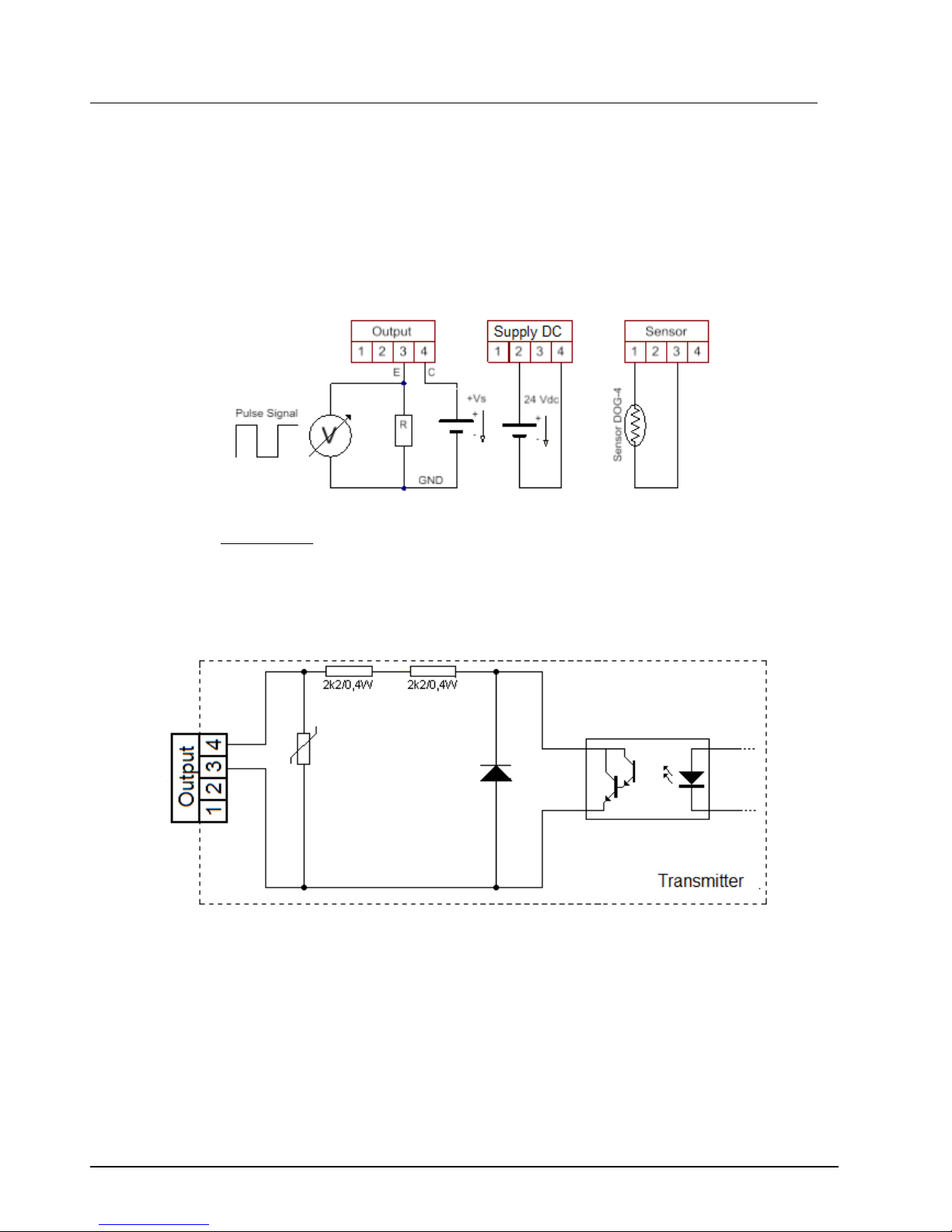
9.4 Terminal assignment of the DOG-4… reader/transducer
230 V
AC
110 VAC
24 VAC
24 V
DC
Output
Sensor
L = 230 V/110 V/24 V outer conductor + = supply DC+
N= 230 V/110 V/24 V neutral conductor - = supply DC-
E = emitter optical coupler
C = collector optical coupler
I-= sensor conductor
I+= sensor conductor
Supply
black
1 2 3 4
L N
+ -
Output
orange
1 2 3 4
E C
Sensor
blue
1 2 3 4
+ -
for AC
for DC
Page 14
DOG-4
page 14 DOG-4 K08/0818
U
HIGH
= ; U
LOW
< 0.5 V
Example: Vs = 24 VDC: U
HIGH
=17 VDC@ R=10 kOhm, U
HIGH
=23 VDC@R=80 kOhm,
R
R+4.4 kΩ
Optical coupler output, external supply max. 30 VDC, I
max
= 50 mA
Page 15

DOG-4
DOG-4 K08/0818 page 15
9.5 Terminal assignment of the electronic option
G0/H0/I0/K0/M0/N0/O0/P0
With the electronic option G0/H0/M0/N0, the reader/transducer is located together
with the flow controller/flow computer prewired in the plastic wall housing. The
connection terminal strip is located underneath the terminal cover. This must be
removed for the electrical connection.
Note:
Additional pressure and temperature sensors are required for the electronic options
M0/N0/O0/P0 (flow computer). These sensors are not included in the scope of delivery.
Page 16

DOG-4
page 16 DOG-4 K08/0818
Wiring diagram electronic option DOG-4 G0/H0/I0/K0
Wiring diagram electronic option DOG-4 L0
Wiring diagram electronic option DOG-4 M0/N0/00/P0
Note:
There is installation space for 2 additional Zener barriers in the housing if the
pressure/temperature sensors do not have the required certification. Establishing
contact in Ex areas can take place via terminals 17 to 20. The required cabling is the
responsibility of the installer.
Page 17

DOG-4
DOG-4 K08/0818 page 17
9.6 Connections of DOG-4 Transmitter with KOBOLD Evaluation
Electronics ZED-X and ZOK-Zx
DOG-4 connection with ZED-Zx
1,2 kOhm
Page 18

DOG-4
page 18 DOG-4 K08/0818
DOG-4 connection with ZOK-ZxP
Notes:
* The sensor supply from ZOK-ZxP must be set to 8 VDC.
From the software menu of ZOK-Zx, the ‘Sensor type’ must be set to ‘PNP’
(For details please see the operating manual of ZOK-Zx electronics).
Page 19

DOG-4
DOG-4 K08/0818 page 19
Connection example for DOG-4 with ZOK-ZxK
The sensor type must be set to "PNP" in the ZOK-ZX software menu (see operating
manual ZOK-Zx electronics).
Page 20

DOG-4
page 20 DOG-4 K08/0818
10. Startup
During startup, ensure that the shut-off valves upstream and downstream of the
device are opened slowly. Avoid increasing the flow velocity to prevent the discharge
rate from damaging the sensor.
The output frequency of the DOG-4 is proportional to the measuring range.
In the event of a sensor fault (breakdown or short circuit) the transistor output is
permanently connected. During self-diagnosis, the transistor output is switched to the
high-resistance state.
11. Setup and operation of the flow controller/flow
computer (option G0/H0/I0/K0/M0/N0/L0/O0/P0)
The integrated flow controller/flow computer are preset and calibrated at the factory.
See the separate operating instructions for the DOG-4G0/H0 and the DOG-4M0/N0
for details.
Page 21

DOG-4
DOG-4 K08/0818 page 21
12. Transmitter error message
12.1 Status display not illuminated
Check terminal “230 VAC” of the terminal assignment.
Check supply voltage
12.2 OPERATING illuminated green but no
output signal
Check terminal “Output” of the terminal assignment
12.3 RANGE illuminated yellow
Measuring range overflows or underflows, decrease
or increase flow
12.4 ERROR illuminated red
Short circuit or interruption of the sensor circuit from
the sensor to the transmitter.
Check terminal “Sensor” of the terminal assignment
Defective platinum sensor (target value: 40-60 Ohm)
Page 22

DOG-4
page 22 DOG-4 K08/0818
13. Maintenance
13.1 Replacing the sensor
To replace the sensor, turn off the flow of medium and discharge the pressure in the
lines. For versions with ball valves, it is
sufficient to simply shut these.
Demounting (see diagram) is carried out in
the following order:
1) Open the connection box (4 x screws)
2) Unclamp the sensor from the strip terminal
(2 screws)
3) If necessary (due to lack of space or tight
cable arrangement), also unclamp from the
strip terminal, loosen the cable gland and pull
out the cable
4) Loosen the connection box from the plate
(2 x screws)
5) Slowly release the sensor screws and
carefully pull out the sensor. Take care that
no sensor parts remain in the device and also
that no foreign parts fall into the device (2
screws).
Reassembly is in the reverse order. Replac the O-rings with the new ones supplied
with the sensor. Uniformly tighten the sensor screws crosswise.
13.2 Disassembly and cleaning the Flowmeter
In the event that the internal section of
the oscillator is dirtied by the medium or
foreign particles fall into this during
replacement of the sensor, the device
must be demounted and cleaned (see
figure at left).
Before the device can be demounted, the
connection box and the sensor must be
unscrewed. For this, see point 13.1.
Then unscrew the screws in the upper
plate, separate the parts and clean the
flow channel of the oscillator on both
sides.
Gasket
above
Gasket
below
2) Order of disassembly
2x Number of screws
NM Requires tightening torque
1) 4x – 1.2-1.5 Nm
2) 4x – 0.3 – 0.5 Nm
5) 4x – 1 – 1.2 Nm
4) 2x – 3 – 4Nm
3) 1x – 4 – 5Nm
Page 23

DOG-4
DOG-4 K08/0818 page 23
Do not use any sharp objects or
aggressive cleaning agents. These
could damage the oscillator, causing
measurement inaccuracies or
breakdown of the device. Check the
inflow and discharge channel and
clean if necessary.
Reassembly takes place in the
reverse order. The two gaskets must
be replaced and are included in the
repair set.
Tighten the screws uniformly with a
torque of 24 to 27 Nm. The figure at
the lower left shows the required
order when tightening. Otherwise the
device may leak or be damaged.
Flow channel top
Flow channel
bottom
Page 24

DOG-4
page 24 DOG-4 K08/0818
14. Technical Data
Measuring accuracy: 1,5% of meas. value (at Qt-100%*)
5% of measured value (at 1%-Qt*)
*The lower limit Qt depends on the density.
Qt = 8% at density 1 kg/m³
Qt = 4% at density 2 kg/m³
Qt = 2% at density 4 kg/m³
Qt = 1% at density 8 kg/m³
Repeatability: 0,1% of measured value
Media temperature: -20 ...+120 °C (non ATEX version)
-20 ...+60 °C (ATEX version)
Ambient temperature: -25 …+80 °C (non ATEX version)
-25…+60 °C (ATEX version)
Operating pressure: DOG-42xxx25…DOG-42xxx50…: PN 40
DOG-42xxx80…DOG-42xxx1F…: PN 16
Span: 1:100
Sensor: platinum sensor
Protection: IP 65
Materials (Transmitter)
Housing: stainless steel 1.4404/316L
Orifice: stainless steel 1.4404/316L
Measuring head: polyphenylene sulfide (PPS)
Sensor: platinum
Gaskets: Klingersil® C-4265, NBR
Ball valves: stainless steel
Page 25

DOG-4
DOG-4 K08/0818 page 25
14.1 Electronic options
Electronics DOG-…A0/B0
(Transducer with/without ATEX certification)
Power supply A/B: 230 V
AC
± 10 %, 50…60 Hz
Power supply C/D: 110 V
AC
± 10 %, 50…60 Hz
Power supply E/F: 24 V
AC
± 20 %, 50…60 Hz
Power supply R: 24 V
DC
± 20 %
Input: Platinum sensor (Allowed distance:
max. 50 m to transmitter)
Output: Opto coupler, frequency linear to flow
V
CE
: 12-24 V (recommended),
max. 30 V
I
C
: max. 50 mA
P
tot
: 100 mW at 25 °C
Derating: 0.91 mW/°C
Ambient temperature: -25…+60 °C
Protection: IP20
Ex-version(A):
ATEX
Transducer: II (1)G [Ex ia Ga] IIC
Sensor: II 1 G Ex ia IIC T4 Ga
IECEx
Transducer: [Ex ia Ga] IIC
Sensor: Ex ia IIC T4 Ga
Mounting: DIN Rail
Dimensions:
Width: 45 mm
Heigth: 105.6 mm
Depth: 113.6 mm
Weight: approx. 200 g
Page 26

DOG-4
page 26 DOG-4 K08/0818
Electronics DOG-…G0/H0
(Transducer without/with ATEX certification and Flow rate/Unit counter, with
current/pulse output)
Display: alphanumeric LCD, UV-resistant, with displayed
functions:
Compensated flow rate
(7 digits, 17 mm high)
Compensated total
(7 digits, 17 mm high)
resettable
Accumulated total
(11 digits, 8 mm high)
not resettable
Units: Flow: m3, cf, scf, Nm
3
Time units: /sec, /min, /hr, /day
Total: m3
Accumulated total: m3
Decimal places: Flow: 0, 1, 2 or 3
Total: 0, 1, 2 or 3
Accumulated total: according to selection for total
Backlightning: yes
Signal input: Flow: DOG-4 sensor
Power supply:
G/H: 230 V
AC
± 10 %, 50…60 Hz
I0/K0: 110 VAC ± 10 %, 50…60 Hz
L0: 24 VDC ± 20 %
Electrical connection: 4 x M16 x 1.5 cable gland
Housing material: ABS with PC cover
Weight: approx. 1800 g
Analogue output: 4…20 mA (active)
10-Bit resolution, 3-wire
Pulse output: PNP, 24 V
DC
active max. 50 mA,
scaled according to linearised accumulated total
(e.g. pulse every 12 liters)
Pulse duration: user defined 0.008 s…2 s
max. frequency: 64 HZ
Protection: IP65
Mounting: Wall mounting
Data protection: EEPROM backup, backup of running totals every
minute, Data retention at least 10 years
Communication: Modbus RTU RS485 2-wire
(optional, other Modbus versions on request)
Page 27

DOG-4
DOG-4 K08/0818 page 27
Electronic Options DOG-…M0/N0/O0/P0
(Transducer without/with ATEX certification and Flow computer)
Display: Alphanumeric LCD, UV-resistant with
Displayed functions:
Compensated Flow rate
(7 digits, 17 mm high)
Compensated total:
(7 digits, 17 mm high)
resettable
Accumulated total
(11 digits, 8 mm high)
not resettable
Actual line temperature (6 digits)
Actual line pressure (6 digits)
Units: Flow: m3, cf, scf, Nm3
Time units: /sec, /min, /hr, /day
Total: m3
Accumulated total: m3
Temperature: °C, °F, or K
Pressure: mbar, bar PSI
Decimals: Flow: 0, 1, 2 or 3
Total: 0, 1, 2 or 3
Accumulated total: according to selection for total
Temperature/Pressure: 1
Backlightning: yes
Signal input: Flow: DOG-4 sensor
Temperature: PT100, 2- or 3-wire
Pressure: 0(4)…20 mA (passive),
14-Bit resolution, 2- or 3-wire
Power supply:
M/N: 230 V
AC
± 10 %, 50…60 Hz
O/P: 110 VAC ± 10 %, 50…60 Hz
Electrical Connection: 5 x M16 x 1.5 cable gland
Housing material: ABS with PC cover
Weight: approx. 1800 g
Analogue output: 4…20 mA (active),
10-Bit resolution, 3-wire
Pulse output: PNP, 24 VDC active max. 50 mA,
scaled according to linearised accumulated total
(e.g. pulse every 12 liters)
Pulse duration: user defined
0.001 s…10 s
max. frequency 500 Hz
Protection: IP65
Mounting: Wall mounting
Data protection: EEPROM backup, backup of running totals every
minute, Data retention at least 10 years
Communication: Modbus RTU RS485 2-wire
(optional, other Modbus versions on request)
Page 28

DOG-4
page 28 DOG-4 K08/0818
Display
Note: Temperature and pressure sensors are not included in scope of delivery.
Page 29

DOG-4
DOG-4 K08/0818 page 29
15. Order Details
Order details for DOG-4 (Example: DOG-4200 S 50 0 A0 0)
Measuring
range air
[m
3
/h]
Model
Material
st.steel
Pressure
rating
[PN]
Connection
flange
[size/type]
Ball valve
Electronics
Options
0,12...12
DOG-42S0S25..
10…40 bar
DN25
0 = without
ball valve
1 = with ball
valve
B0 = Frequency output,
230 V
AC
A0 = as ‘B’, with ATEX/IECEx
G0 = Unit counter, pulse
output, analogue output,
230 V
AC
H0 = as ‚G‘, with ATEX/IECEx
M0 = Flow computer, pulse
output, analogue output,
230 V
AC
N0 = as ‚M‘, with ATEX/IECEx
C0 = as ‘B0’, 110 V
AC
D0 = as ‘A0’, 110 VAC
E0 = as ‘B0’, 24 V
AC
F0 = as ‘A0’, 24 V
AC
R0 = as ‘B0’, 24 VD
C
I0 = as ‘G0’, 110 V
AC
K0 = as ‘I0’, 110 V
AC
L0 = as ‘G0’, 24 VD
C
O0 = as ‘M0’, 110 V
AC
P0 = as ‘N0’, 110 V
AC
Y0 = Special (specify in clear
text)
0 = without
Y = Special option
(specify in
clear text)
DOG-42S0S40..
DN40
DOG-42S0S50..
DN50
DOG-42S0B25..
Klasse 300
ANSI 1“
DOG-42S0B40..
ANSI 1½“
DOG-42S0B50..
ANSI 2“
0.2…20
DOG-4200S25..
10…40 bar DN25
DOG-4200S40..
DN40
DOG-4200S50..
DN50
DOG-4200B25..
Class 300 ANSI 1“
DOG-4200B40..
ANSI 1½“
DOG-4200B50..
ANSI 2“
0.35…35
DOG-4250S25..
10…40 bar DN25
DOG-4250B25..
Class 300 ANSI 1“
0.7…70
DOG-42A0S25..
10…40 bar DN25
DOG-42A5B25..
Class 300 ANSI 1“
0.9…90
DOG-42A5S40..
10…40 bar DN40
DOG-42A5B40..
Class 300 ANSI 1½“
1.1…110
DOG-42B0S50..
10…40 bar DN50
DOG-42B0B50..
Class 300 ANSI 2“
1.4…140
DOG-42B5F80..
16 bar DN80
DOG-42B5S80..
40 bar DN80
DOG-42B5A80..
Class 150 ANSI 3“
DOG-42BFB80..
Class 300 ANSI 3“
2…200
DOG-42C0S40..
10…40 bar DN40
DOG-42C0B40..
Class 300 ANSI 1½“
2.5…250
DOG-42C5S50..
10…40 bar DN50
DOG-42C5B50..
Class 300 ANSI 2“
2.7…270
DOG-42D0F1H..
16 bar DN100
DOG-42D0S1H..
40 bar DN100
DOG-42D0A1H..
Class 150 ANSI 4“
DOG-42D0B1H..
Class 300 ANSI 4“
4.5…450
DOG-42D5F80..
16 bar DN80
DOG-42D5S80..
40 bar DN80
DOG-42D5A80..
Class 150 ANSI 3“
DOG-42D5B80..
Class 300 ANSI 3“
6.0…600
DOG-42E0F1F..
16 bar DN150
DOG-42E0S1F..
40 bar DN150
DOG-42E0A1F..
Class 150 ANSI 6“
DOG-42E0B1F..
Class 300 ANSI 6“
6.5…650
DOG-42E5F1H..
16 bar DN100
DOG-42E5S1H..
40 bar DN100
DOG-42E5A1H..
Class 150 ANSI 4“
DOG-42E5B1H..
Class 300 ANSI 4“
Page 30

DOG-4
page 30 DOG-4 K08/0818
Order details for DOG-4 (Example: DOG-4200 S 50 0 A0 0) (continuation)
Measuring
range air
[m
3
/h]
Model
Material
st. steel
Pressure
rating
[PN]
Connection
flange
[size/type]
Ball valve
Electronics
Options
8.0…800
DOG-42F0F80..
16 bar DN80
0 = without
ball valve
1 = with ball
valve
B0 = Frequency output,
230 V
AC
A0 = as ‘B’, with ATEX/IECEx
G0 = Unit counter, pulse
output, analogue output,
230 V
AC
H0 = as ‚G‘, with ATEX/IECEx
M0 = Flow computer, pulse
output, analogue output,
230 V
AC
N0 = as ‚M‘, with ATEX/IECEx
C0 = as ‘B0’, 110 V
AC
D0 = as ‘A0’, 110 VAC
E0 = as ‘B0’, 24 V
AC
F0 = as ‘A0’, 24 V
AC
R0 = as ‘B0’, 24 VD
C
I0 = as ‘G0’, 110 V
AC
K0 = as ‘I0’, 110 V
AC
L0 = as ‘G0’, 24 VD
C
O0 = as ‘M0’, 110 V
AC
P0 = as ‘N0’, 110 V
AC
Y0 = Special (specify in clear
text)
0 = without
Y = Special
option
(specify in
clear text)
DOG-42F0S80..
40 bar DN80
DOG-42F0A80..
Class 150 ANSI 3”
DOG-42F0B80..
Class 300 ANSI 3”
10…1000
DOG-42F5F1H..
16 bar DN 100
DOG-42F5S1H..
40 bar DN 100
DOG-42F5A1H..
Class 150 ANSI 4“
DOG-42F5B1H..
Class 300 ANSI 4“
12…1200
DOG-42G0F1F..
16 bar DN 150
DOG-42G0S1F..
40 bar DN 150
DOG-42G0A1F..
Class 150 ANSI 6“
DOG-42G0B1F..
Class 300 ANSI 6“
DOG-42G0E2H..
10 bar DN 200
DOG-42G0F2H..
16 bar DN 200
DOG-42G0S2H..
40 bar DN 200
DOG-42G0A2H..
Class 150 ANSI 8“
DOG-42G0B2H..
Class 300 ANSI 8“
25…2500
DOG-42G5E2H..
10 bar DN 200
DOG-42G5F2H..
16 bar DN 200
DOG-42G5S2H..
40 bar DN 200
DOG-42G5A2H..
Class 150 ANSI 8“
DOG-42G5B2H..
Class 300 ANSI 8“
30…3000
DOG-42H0F1F..
16 bar DN 150
DOG-42H0S1F..
40 bar DN 150
DOG-42H0A1F..
Class 150 ANSI 6“
DOG-42H0B1F..
Class 300 ANSI 6“
60…60001)
DOG-42H5E2H..
10 bar DN200
DOG-42H5F2H..
16 bar DN 200
DOG-42H5S2H..
40 bar DN 200
DOG-42H5A2H..
Class 150 ANSI 8“
DOG-42H5B2H..
Class 300 ANSI 8“
Special
DOG-42YYYYY.. Sonder Sonder
1)
Calibrated up to 4000 m3/h. Higher flow rate calibration on request.
Page 31

DOG-4
DOG-4 K08/0818 page 31
16. Pressure Loss/Flow
The diagram applies for gases with a density of air at NPT (0 °C and 1013.25 mbar).
The pressure loss is always proportional to the density of the gas. For example, the
pressure loss doubles at 100% higher operating pressure.
Calculating the Actual Density
The actual density can be calculated with the following formula:
D0 = density at 1 bar abs. and 0 °C (= 273 K) T = temperature in K
(= °C + 273 for example 20 °C = 273 + 20 = 293 K) T0 = 273 K
P = operating pressure in bar (absolute pressure)
Calculating the Norm Flow
QN = norm flow at 1.013 bar abs. and 0 °C
Q = operating flow
P = operating pressure in bar (absolute pressure)
T = operating temperature in K
Pressure drop [mbar]
Page 32

DOG-4
page 32 DOG-4 K08/0818
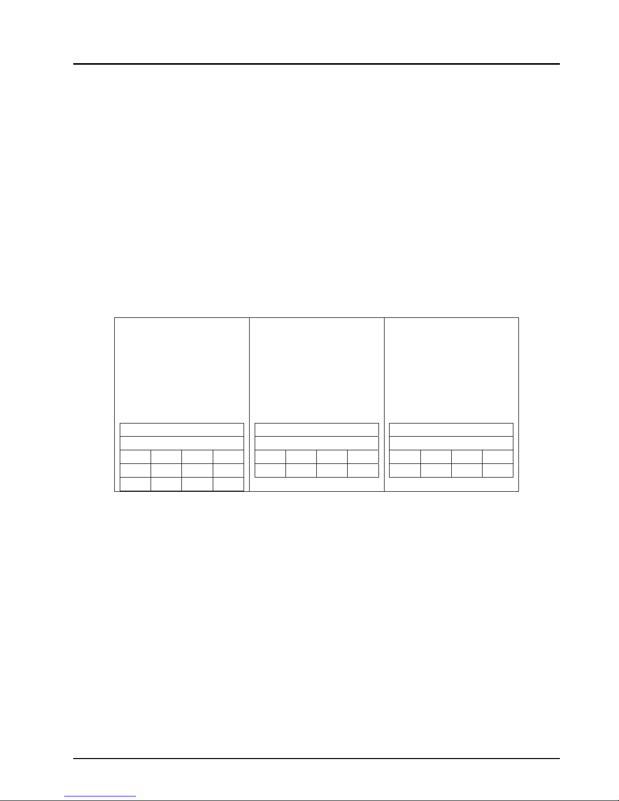
17. Dimensions
Dimensions and Weights DOG-4 (without ball valve)
Dimensions and Weights DOG-4 (with ball valve)
Dimensional details without ball valve
DN
[mm] L (Length)
[mm]
H
(Height)
[mm]
øD
(outer ø)
[mm]
øK
(pitch circle)
[mm]
øL
(hole ø)
[mm]
Ød1
(sealing surface)
[mm]
No. of
screws
Screw size Weight
[kg]
25 300 150 115 85 14 68 4 M12 8,1
40 300 158 150 110 18 88 4 M16 10
50 300 164 165 125 18 102 4 M16 11,6
80 300 178 200 160 18 138 8 M16 14,4
100 320 191 220 180 18 58 8 M16 16,6
150 320 218 285 240 22 212 8 M20 24,8
200 320 243 340 295 22 268 8 M20 35,8
Page 33

DOG-4
DOG-4 K08/0818 page 33
Dimensions Electronics DOG-…A/B
Dimensions Electronics DOG-…G/H/M/N
Accessories (optional)
Replacement sensor
Sealing for oscillator
Recalibration set for transmitter
Dimensional details with ball valve
DN
[mm] L (Length)
[mm]
H
(Height
)
[mm]
øD
(outer ø)
[mm]
øK
(pitch circle)
[mm]
øL
(hole ø)
[mm]
Ød1
(sealing surface)
[mm]
No. of
screws
Screw size Weight
[kg]
25 300 166 115 85 14 68 4 M12 8,5
40 300 174 150 110 18 88 4 M16 10,4
50 300 180 165 125 18 102 4 M16 12
80 300 194 200 160 18 138 8 M16 14,8
100 320 207 220 180 18 58 8 M16 16,9
150 320 234 285 240 22 212 8 M20 25,3
200 320 259 340 295 22 268 8 M20 36,3
Page 34

DOG-4
page 34 DOG-4 K08/0818
18. EU Declaration of Conformance
We, KOBOLD Messring GmbH, Hofheim-Ts, Germany, declare under our sole
responsibility that the product:
Oscillation Flowmeter Model: DOG-4
to which this declaration relates is in conformity with the standards noted below:
EN 61326:2013-07 Electrical equipment for measurement, control and laboratory
use - EMC requirements - Part 1: General requirements
EN 13480-1:2013-11 Metallic industrial piping - Part 1: General
EN 50581:2012 Technical documentation for the assessment of electrical and
electronic products with respect to the restriction of hazardous
substances
zusätzlich DOG-4…A/H/N/D/F/P:
EN 60079-0:2014-06 Explosive atmospheres - Part 0: Equipment –
General requirements
EN 60079-11:2012 Explosive atmospheres - Part 11: Equipment protection by
intrinsic safety "i"
EN 60079-26:2007 Explosive atmospheres - Part 26: Equipment with equipment
protection level (EPL) Ga
Also the following EU guidelines are fulfilled:
2014/30/EU EMC Directive
2014/35/EU Low Voltage Directive
2011/65/EU RoHS (category 9)
2014/68/EU PED
Category III (IV) Diagram 1, vessel, group 1 dangerous fluids
Module D, marking CE0575
Notified body: DNV GL
Certificate No. PEDD000000R
additional DOG-4…A/H/N/D/F/P:
2014/34/EU Equipment and protective systems intended for use in
potentially explosive atmospheres (ATEX 100a)
Production quality assurance
Certification no.: BVS 15 ATEX ZQS / E 110
Notified body: DEKRA EXAM
Identification no.: 0158
Hofheim, 31. July 2018
H. Peters M. Wenzel
General Manager Proxy Holder
Page 35

DOG-4
DOG-4 K08/0818 page 35
19. ATEX-Certificate
Page 36

DOG-4
page 36 DOG-4 K08/0818
Page 37

DOG-4
DOG-4 K08/0818 page 37
Page 38

DOG-4
page 38 DOG-4 K08/0818
Page 39

DOG-4
DOG-4 K08/0818 page 39
Page 40

DOG-4
page 40 DOG-4 K08/0818
Page 41

DOG-4
DOG-4 K08/0818 page 41
20. IECEx-Certificate
Page 42

DOG-4
page 42 DOG-4 K08/0818
Page 43

DOG-4
DOG-4 K08/0818 page 43
Page 44

DOG-4
page 44 DOG-4 K08/0818
 Loading...