

Page 1
Operating Instructions
for
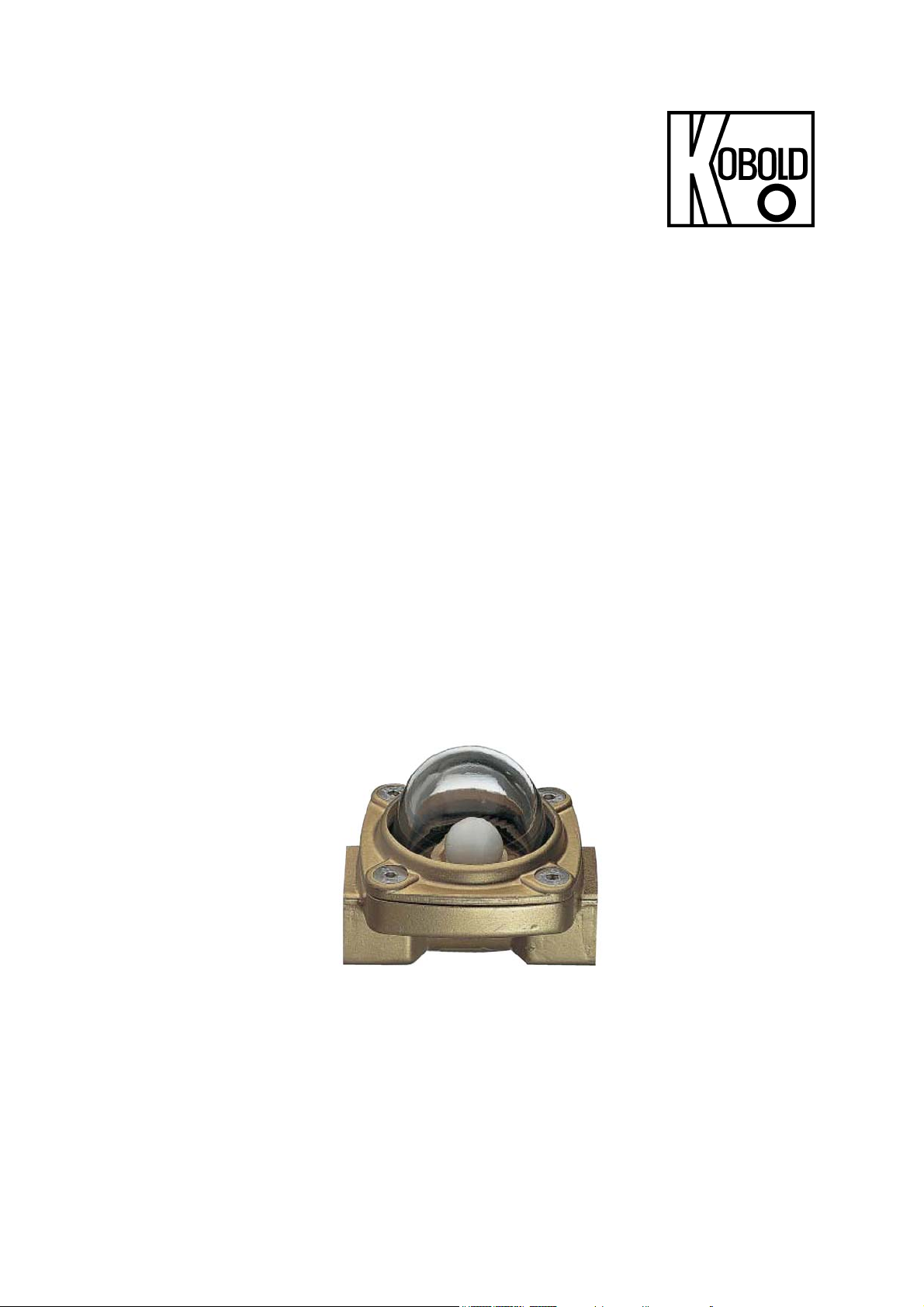
Ball Type Flow Indicator
Model: DKB
Page 2

DKB
1. Contents
Contents ........................................................................................................ 2
1.
2. Note .............................................................................................................. 3
3. Instrument Inspection .................................................................................... 3
4. Regulation Use .............................................................................................. 3
5. Operating Principle ........................................................................................ 4
6. Mechanical Connection ................................................................................. 4
7. Technical Information .................................................................................... 4
8. Order Codes ................................................................................................. 5
9. Dimensions ................................................................................................... 6
10.ATEX - Declaration of the Manufacturer ....................................................... 8
10.1 General ................................................................................................ 8
10.2 Areas of use ......................................................................................... 8
10.3 Evaluation ............................................................................................ 8
Manufactured and sold by:
Kobold Messring GmbH
Nordring 22-24
D-65719 Hofheim
Tel.: +49(0)6192-2990
Fax: +49(0)6192-23398
E-Mail: info.de@kobold.com
Internet: www.kobold.com
page 2 DKB K01/1115
Page 3

DKB
2. Note
Please read these operating instructions before unpacking and putting the unit
into operation. Follow the instructions precisely as described herein.
The devices are only to be used, maintained and serviced by persons familiar
with these operating instructions and in accordance with local regulations
applying to Health & Safety and prevention of accidents.
When used in machines, the measuring unit should be used only when the
machines fulfil the EC-machine guidelines.
as per PED 2014/68/EU
In acc. with Article 4 Paragraph (3), "Sound Engineering Practice", of the
PED 2014/68/EU no CE mark.
Diagram 8, Pipe, Group 1 dangerous fluids
3. Instrument Inspection
Instruments are inspected before shipping and sent out in perfect condition.
Should damage to a device be visible, we recommend a thorough inspection of
the delivery packaging. In case of damage, please inform your parcel service /
forwarding agent immediately, since they are responsible for damages during
transit.
Scope of delivery:
The standard delivery includes:
Ball Type Flow Indicator model: DKB
Operating Instructions
4. Regulation Use
Any use of the Ball Type Flow Indicator, model: DKB, which exceeds the
manufacturer’s specification may invalidate its warranty. Therefore, any resulting
damage is not the responsibility of the manufacturer. The user assumes all risk
for such usage.
DKB K01/1115 page 3
Page 4

DKB
5. Operating Principle
During flow the plastic ball heaves out of its seat and indicates a flow movement
in the pipeline. If the flow stops the ball will fall back into its seat.
6. Mechanical Connection
Before installation
Remove all transport restraints and make sure that none of the packing
remains in the instrument.
Make sure that the maximum allowed operating pressures and service
temperatures are not exceeded (see 7. Technical Information)
Mount the Flow Indicator horizontally with the glass dome on top and tension-
free into the pipe.
Avoid water hammer in the measuring tube e.g. caused through a sudden shut
off the flow.
If possible, check after mechanical installation that the threaded joint/pipe
connection is tight.
7. Technical Information
DKB-11...
Housing: brass (MS-58)
Glass dome: Borosilicate glass
Ball: POM
Sealing: EPDM
Rings: brass (MS-58)
Screws: st. steel
DKB-21...
Housing: brass (MS-58)
Glass dome: Borosilicate glass
Ball: PTFE
Sealing: FPM
Rings: brass (MS-58)
Screws: st. steel
page 4 DKB K01/1115
Page 5

DKB
DKB-22...
Housing: stainless steel 1.4436, 1.4410
Glass dome: Borosilicate glass
Ball: PTFE
Rings: Klinger SIL® C4400, FPM
Screws: st. steel, rust-proof
Connection DKB-x1
G 1/8
R06
1/8” NPT
N06
Connection DKB-22
G 1/4
R08
G 1/4
R08
1/4” NPT
N08
G 3/8
R10
G 3/8
R10
3/8” NPT
N10
G 1/2
R15
G 1/2
R15
1/2” NPT
N15
G 3/4
R20
G 3/4
R20
3/4” NPT
N20
G 1
R25
G 1
R25
1” NPT
N25
G 1 1/2
R40
8. Order Codes
Order example: DKB-1101H R06
Indication range Model Connection
Water
[L/min]
0.05 - 15 1
0.05 - 20 1
0.06 - 45 1
0.07 - 50 1
0.18 - 105 0.5
0.14 - 105 0.5
* max. flow
Order example: DKB-2202H R08
Indication range Model Connection
Water
[L/min]
0.3 – 4 0.1
0.3 - 8 0.1
0.3 – 12 0.1
2.5 – 25 0.2
4 – 40 0.2
11 - 60 0.3
* at 2m/s
∆ P*
[bar]
∆ P*
[bar]
DKB-11.. DKB-21.. G-thread NPT-thread
DKB-1101H.. DKB-2101H.. R06 N06
DKB-1102H.. DKB-2102H.. R08 N08
DKB-1103H.. DKB-2103H.. R10 N10
DKB-1104H.. DKB-2104H.. R15 N15
DKB-1105H.. DKB-2105H.. R20 N20
DKB-1106H.. DKB-2106H.. R25 N25
DKB-22.. G-thread
DKB-2202H.. R08
DKB-2203H.. R10
DKB-2204H.. R15
DKB-2205H.. R20
DKB-2206H.. R25
DKB-2207H.. R40
DKB K01/1115 page 5
Page 6

DKB
9. Dimensions
Model P
DKB-..01H
DKB-..02H
DKB-..03H
DKB-..04H
DKB-..05H
DKB-..06H
T
max
6 bar 120 °C G ⅛ ⅛” 8 56 41 50 0,3
6 bar 120 °C G ¼ ¼” 10 56 41 50 0,28
6 bar 120 °C G ⅜ ⅜” 14 73 53 67 0,57
6 bar 120 °C G ½ ½” 14 73 53 67 0,54
6 bar 120 °C G ¾ ¾” 16 109 72 94 1,41
6 bar 120 °C G 1 1” 18 109 72 94 1,30
G NPT L1
max
[mm] L [mm] A [mm] B [mm]
Weight
[kg]
page 6 DKB K01/1115
Page 7

DKB
Model P
DKB-2202H
DKB-2203H
DKB-2204H
DKB-2205H
DKB-2206H
DKB-2207H
T
max
16 bar 200 °C G ¼ 28 12 76 67 60 0,8
16 bar 200 °C G ⅜ 28 16 76 67 60 0,7
16 bar 200 °C G ½ 28 14 76 67 60 0,7
16 bar 200 °C G ¾ 45 18 89 78 60 1,4
16 bar 200 °C G 1 45 18 89 78 60 1,3
16 bar 200 °C G 1½ 62 30 118 95 77 2,5
G SW X
max
[mm] L [mm] H [mm] B [mm]
Weight
[kg]
DKB K01/1115 page 7
Page 8

DKB
10. ATEX - Declaration of the Manufacturer
10.1 General
Risk analysis report pursuant to EN 13463 (positive list) for use in category
2 Explosion Risk Area was done.
When used properly, and being a piece of mechanical equipment, the ball type
flow indicator type DKB-x1****** does not have its own potential source of
ignition; it is not assigned an ID in the sense of the ATEX Directive.
10.2 Areas of use
The units can be used as follows:
In the Zone 2 (Gas-Ex, Cat. 3G) into explosion group of IIA, IIB and IIC
In the Zone 22 (Dust-Ex, Category 3D) at non-conductive dusts with a
minimum igniting energy of > 3 mJ
In the Zone 1 (Gas-Ex, Cat. 2G) into explosion group of IIA, IIB and IIC
In the Zone 21 (Dust-Ex, Category 2D) at non-conductive dusts with a
minimum igniting energy of > 3 mJ
In normal use, the flow indicators are completely filled with medium. Zone 2
– or Zone 1 – conditions may prevail for a short time.
10.3 Evaluation
Adherence to EN 13463, Parts 1 to 8 (Mechanical Explosion Prevention)
When used properly, the flow indicator does not have its own potential source of
ignition as per the conditions of Categories 2 and 3. It does however fulfil the
following requirements:
The manufacturer has subjected all exposed parts of the device to the impact
and environmental strain tests pursuant to EN 13463-1.
When installed, the device must be protected against external
energy impact – or measures should be taken to take into account
any possible zone violations in the system.
The outer casing of the device is made of brass and borosilicate glass; there
are no light metal parts.
Hofheim, 12. Nov. 2015
H. Peters M. Wenzel
General Manager Proxy Holder
page 8 DKB K01/1115
 Loading...