

Page 1

Operating Instruction
for
Flow Transmitter
Model: DF-MA
Page 2

DF-MA
Page 2 DF-MA K03/0118
1. Contents
1. Contents ........................................................................................................ 2
2. Note .............................................................................................................. 3
3. Instrument Inspection .................................................................................... 3
4. Regulation Use .............................................................................................. 4
5. Operating Principles ...................................................................................... 5
6. Mechanical Connection ................................................................................. 5
7. Electrical Connection .................................................................................... 6
8. Electrical Commissioning of the Instruments ................................................ 7
9. Mechanical Commissioning of the Instrument ............................................... 7
10.Maintenance ................................................................................................. 7
11.Technical Information .................................................................................... 8
12.Order Codes ................................................................................................. 8
13.Dimensions ................................................................................................... 9
14.Recommended Spare Parts .......................................................................... 9
15.EU Declaration of Conformance .................................................................. 10
Manufactured and sold by:
Kobold Messring GmbH
Nordring 22-24
D-65719 Hofheim
Tel.: +49(0)6192-2990
Fax: +49(0)6192-23398
E-Mail: info.de@kobold.com
Internet: www.kobold.com
Page 3
DF-MA
DF-MA K03/0118 Page 3
2. Note
Please read and take note of these operating instructions before unpacking and
setting the unit for operation, and follow the instructions precisely as described
herein.
The devices are only to be used, maintained and serviced by persons familiar
with these operating instructions and with the prevailing regulation applying to
procedural safety and the prevention of accidents.
By usage in machines, the measuring unit should be used only then when the
machines fulfil the EC-machine guide lines.
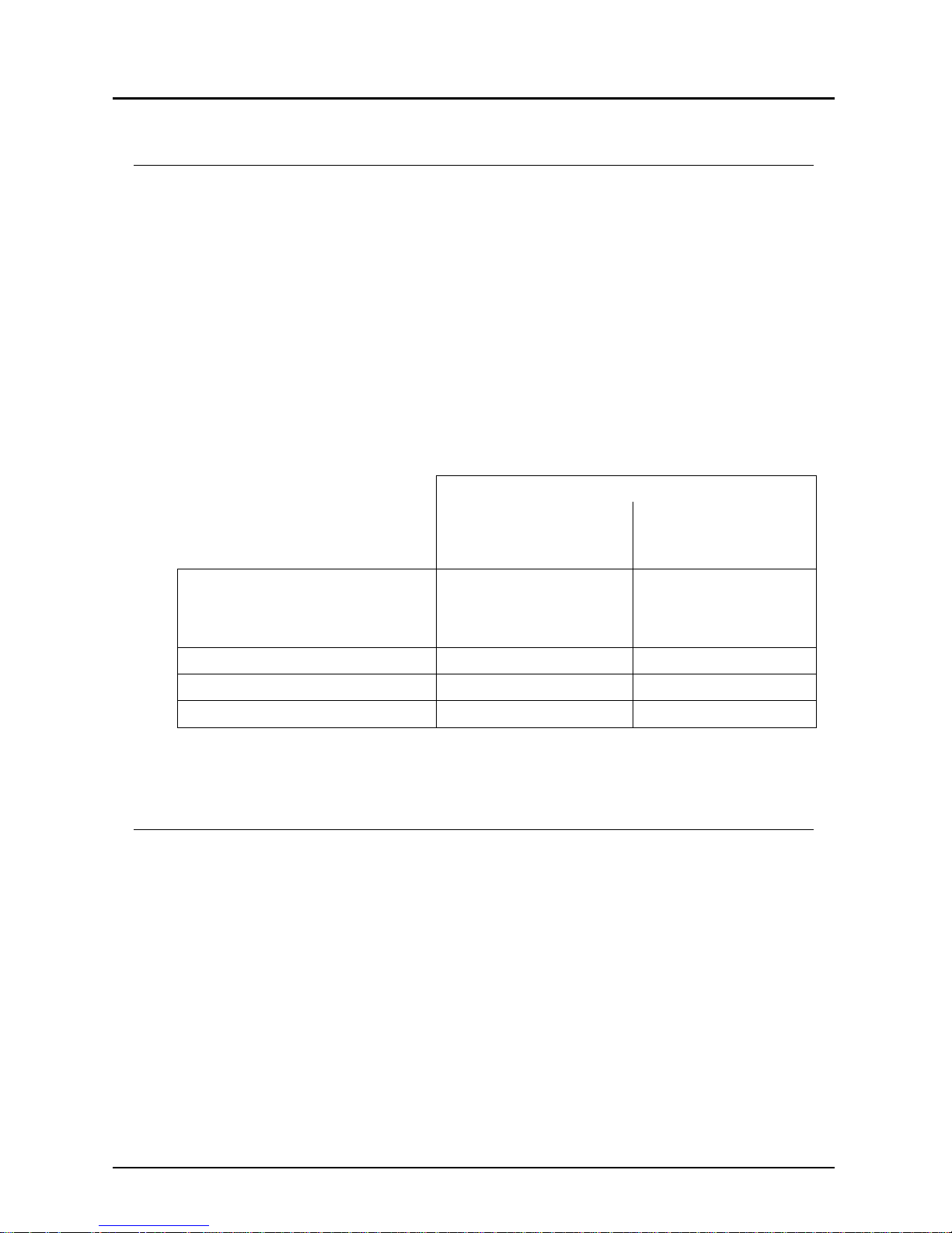
PED 2014/68/EU
In acc. with Article 4 Paragraph (3), "Sound Engineering Practice", of the
PED 2014/68/EU no CE mark.
Pipe
Diagram 8
Group 1
dangerous fluids
Diagram 9
Group 2
no dangerous fluids
All DF-models except
DF-xxG(H)R32
DF-xxG(H)R40
Art. 4, § 3 Art. 4, § 3
DF-xxGR32../DF-xxGR40 not deliverable Art. 4, § 3
DF-xxHR32../DF-xxHR40.. Kat. II Art. 4, § 3
DF-xxHF50.. Kat II Art. 4, § 3
3. Instrument Inspection
These devices are checked before dispatch and sent away in perfect condition.
Should the damage to a device be visible, we recommend a thorough inspection
of the delivery packing. In case of damage, please inform your parcel service/
forwarding agent immediately, since they are responsible for damages during
transit.
Scope of delivery:
Flow Transmitter DF-MA
Operating Instructions
Page 4

DF-MA
Page 4 DF-MA K03/0118
4. Regulation Use
The model DF-MA is installed to measure the flow of liquids.
The instrument provides the following facilities:
Analogue Output
For the remote transmission of measured flow rates, the instrument is provided
with an analogue output (DIN IEC 381) with 0-20 mA or 4-20 (see label).
lt is suitable for low viscosity fluids which have no effects on the instrument materials used. If using higher viscosity media large deviations will occur from the flow
range as given in the catalogue. Long threads can lead to the seizure of the rotor.
Likewise, ferritic particles can build up on the rotating vane and lead to faulty
operation or destruction of the rotor. In cases of doubt, please contact the supplier.
Material Combinations
Standard version
High-pressure
version
Material
combination
I II III IV
1)
VI
1)
VII
1)
Order code ..A.. ..B.. ..D.. ..E.. ..G.. ..H..
Connection
types
Pipe thread Pipe thread Pipe thread
Pipe thread
flange
Pipe
thread
Pipe
thread
flange
Case Trogamide Polysulfone
Brass
nickel-plated
St.steel4)
Brass
nickelplated
St.steel
4)
Cover Trogamide Polysulfone Polysulfone Polysulfone
Brass
nickelplated
St.steel
4)
Connection
Brass
nickel-plated
St.steel
4)
Brass
nickel-plated
St.steel
4)
Brass
nickelplated
St.steel
4)
Locking pins Brass Brass Brass - - -
O-rings NBR FPM NBR FPM NBR FPM
Vane POM PTFE POM PTFE POM PTFE
Axle
3)
St.steel
4)
St.steel
4)
St.steel
4)
St.steel
4)
St.steel
4))
St.steel
4)
Bearing
3)
PTFE PTFE PTFE PTFE PTFE PTFE
Screen PTFE
2)
PTFE
2)
PTFE
2)
PTFE
2)
PTFE
2)
PTFE
2)
Max.
operating
pressure
10 bar 10 bar 16 bar 16 bar 100 bar
100 bar
flange
PN 40
Max.
operating
temperature
60 °C 80 °C 80 °C 80 °C 80 °C 80 °C
1) Connection cannot be rotated 2) Stainless St. for model DF 0.5 3) Special version upon request
4) Stainless St.1.4571, 1.4404
Page 5

DF-MA
DF-MA K03/0118 Page 5
5. Operating Principles
A plastic rotating vane rotates on an axle when a flow throughput occurs. A ring
shaped magnet hermetically sealed in the rotating vane transmits this rotary
motion to a Hall sensor mounted outside of the instrument housing. The electronics mounted on the housing converts the frequency signal into an analogue
output.
6. Mechanical Connection
Before installation
Please ascertain whether the actual flow throughput
matches the flow range of the instrument. The flow
range may be obtained from the label.
Warning! If the measuring range is exceeded by more than 20%,
bearing damage may occur.
Please ascertain whether the allowable maximum
operating pressure and operating temperature of the
instruments will not be exceeded.
Make sure that the electrical supply to the instrument
conforms with the equipment operating data.
Remove all transport packing and ascertain that no
packing material is left in the instrument.
The instrument may be installed in any position.
However, the flow must always take place in the
direction of the arrow, while the front face of the
instrument must always be in the vertical plane.
It must be ensured that the instrument housing is continuously filled with the
flow medium, especially for flows from top to bottom. No straight pipe lengths
are necessary at inlet and outlet connections.
Sealing of the connection threads should be carried out with PTFE tape or
similar.
During installation of the instrument, it must be checked that no stress is
applied to the connections. We recommend that the inlet and outlet pipes are
mechanically fixed approximately 50 mm from each instrument connection.
When using material combination IIB,IV,V,VI and VII the instrument connec-
tions may not be rotated.
Check that the connection thread to pipe is fully sealed.
Warning! The threaded connections of the instrument must be
tightened with a suitably sized open ended spanner. Otherwise,
the housing may be stressed which could lead to breakage of the
equipment.
wrong!
right!
Page 6

DF-MA
Page 6 DF-MA K03/0118
7. Electrical Connection
Warning! Make sure that the supply
voltage to the instrument conforms with
the value given on the equipment label.
Ensure that the power is disconnected
during connection of the cable.
For equipment with plug connection solder the
ends of your supply cables in accordance with the
connection plan supplied with the coupling plug.
For equipment with cable connection simply
connect the instrument cable to your supply cable.
Supply cable cross-section: 0.75 mm².
Warning! Incorrect wiring of the connection in the coupling plug or
incorrect wiring of the connection cable can lead to the electronics
being destroyed.
Plug the coupling plug in the socket provided on the equipment (in the case of
instruments with plug connections).
After connection of your external equipment at the connection points the
instrument is ready for operation.
Page 7

DF-MA
DF-MA K03/0118 Page 7
8. Electrical Commissioning of the Instruments
The instrument is delivered ready to operate. The electronics
are matched and calibrated against the signal transmitter.
The calibration screws ('ZERO' and 'RANGE') found behind
the adhesive foil must not be adjusted by the customer. If
they are adjusted, a re-calibration will be required involving
new calculations. Should the electronics be opened any
warranty will become invalid.
As soon as the external power supply to the instrument is
switched on, a green LED will indicate that the unit is ready
for operation. #
9. Mechanical Commissioning of the Instrument
To avoid pressure surges, the flow medium should be slowly introduced into the
instrument.
Warning! Pressure surges from solenoid valves, ball valves or
similar may lead to breakage of the instrument (water hammer). In
the operating condition it must be checked that the instrument
housing is continuously filled with the flow medium.
Warning! Large air bubbles in the instrument housing may lead to
measuring errors or destruction of the bearings.
10. Maintenance
For measured media without contamination, the DF-MA instrument is almost
maintenance-free. As the rotating vane contains magnets, any ferritic particles
present in the medium may lead to problems. In order to avoid such problems we
recommend the installation of a magnet filter e.g.: model filter MF-R.
Should cleaning of the instrument become necessary, the housing cover may
easily be removed to provide access to the internals. After cleaning, the instrument may just as easily be reassembled. Any work on the electronics may only
be undertaken by the supplier; otherwise the warranty will become invalid.
Page 8

DF-MA
Page 8 DF-MA K03/0118
11. T echnical Information
Power input: 3.5 W max.
Power supply: 24 VDC +15% / -10%
24, 110, 230 VAC ±20%
Output: (DIN IEC 381) current source 0(4)-20 mA
floating, 0-10 V (24 V
DC
non-isolated)
Output load: 0-500 Ω (load)
Protection type: IP 65, all-insulated
Ambient temperature: - 25 °C to +80 °C
Accuracy: ± 2.5 % f. s
12. Order Codes
Example: DF-05 A R 06 MAK 0 0
Flow rate
L/min
Model Material
combination
(see trans-
ducer)
Connec-
tion*
Connection sizes
(see measuring sen-
sor for recommended
size)
Electronics Auxiliary
power
Analogue
output
0.08 - 0.50
0.20 - 1.40
0.20 - 2.50
0.30 - 2.60
0.40 - 5.00
0.25 - 6.00
0.50 - 6.00
1.00 - 12.5
1.00 - 24.0
2.00 - 48.0
2.50 - 60.0
5.00 - 120
40.0 - 160
DF-05...
DF-14...
DF-25...
DF-26...
DF-50...
DF-06...
DF-12...
DF-13...
DF-24...
DF-48...
DF-60...
DF-H2...
DF-H6...
A = Trogamide/
Brass
B = PSO/VA
D= Brass
E = St. steel
G = Brass,
100 bar
H = St. steel,
100 bar
R= G female
N = NPT
female
F= Flange
DIN 2527,
PN 40
06= G 1/8
08= G1/4
10= G 3/8
15= G 1/2, DN 15
20= G 3/4
25= G 1, DN 25
32= G 1 1/4
40= G 11/2, DN 40
50= DN 50
MAK= remote sensor with
1,5 m cable connec tion
MAS= remote sensor with
connector
MAG= remote sensor with
connector and
mating connector
0= 230 V
AC
1= 110 V
AC
2= 24 V
AC
3= 24 V
DC
0= 0 - 20 mA
4= 4 - 20 mA
1= 0 - 10 V
Page 9

DF-MA
DF-MA K03/0118 Page 9
13. Dimensions
14. Recommended Spare Parts
1.1) Rotating vane PTFE
1.2) Rotating vane POM
1.3) Rotating vane PTFE with saphire bearings
2.1) Stainless Steel axle / PTFE bearings
2.2) Ceramic axle / PTFE bearings
2.3) Saphire axle with saphire bearings (only for rotating vane 1.3)
3.1.) Cover for instrument housing, Trogamide, including seal
3.2.) Cover for instrument housing, Polysulphone, including seal
4.1.) Transparent cover for electronics housing
5.1) Set of NBR 0-rings
5.2) Set of FPM 0-rings
For spare part ordering we need the serial no. of the instrument.
Page 10

DF-MA
Page 10 DF-MA K03/0118
15. EU Declaration of Conformance
We, KOBOLD-Messring GmbH, Hofheim-Ts, Germany, declare under our sole
responsibility that the product:
Flow Monitor / Transmitter: DF-MA
to which this declaration relates is in conformity with the standards noted below:
EN 61000-6-2:2005
Electromagnetic compatibility (EMC) - Part 6-2: Generic standards - Immunity for
industrial environments
EN 61010-1:2010
Safety requirements for electrical equipment for measurement, control and
laboratory use - Part 1: General requirements
EN 50581:2012
Technical documentation for the assessment of electrical and electronic products
with respect to the restriction of hazardous substances
Also the following EC guidelines are fulfilled:
2014/30/EU EMC Directive
2014/35/EU Low Voltage Directive
2011/65/EU RoHS (category 9)
for DF-xxHR32../DF-xxHR40, Edelstahl, 1 1/4"
2014/68/EU PED
Category III (IV) Diagram 1, vessel, group 1 dangerous fluids
Module D, marking CE0575
Notified body: DNV GL
Certificate No. PEDD0000002
Hofheim, 11. Jan. 2018
H. Peters M. Wenzel
General Manager Proxy Holder
 Loading...