

Page 1
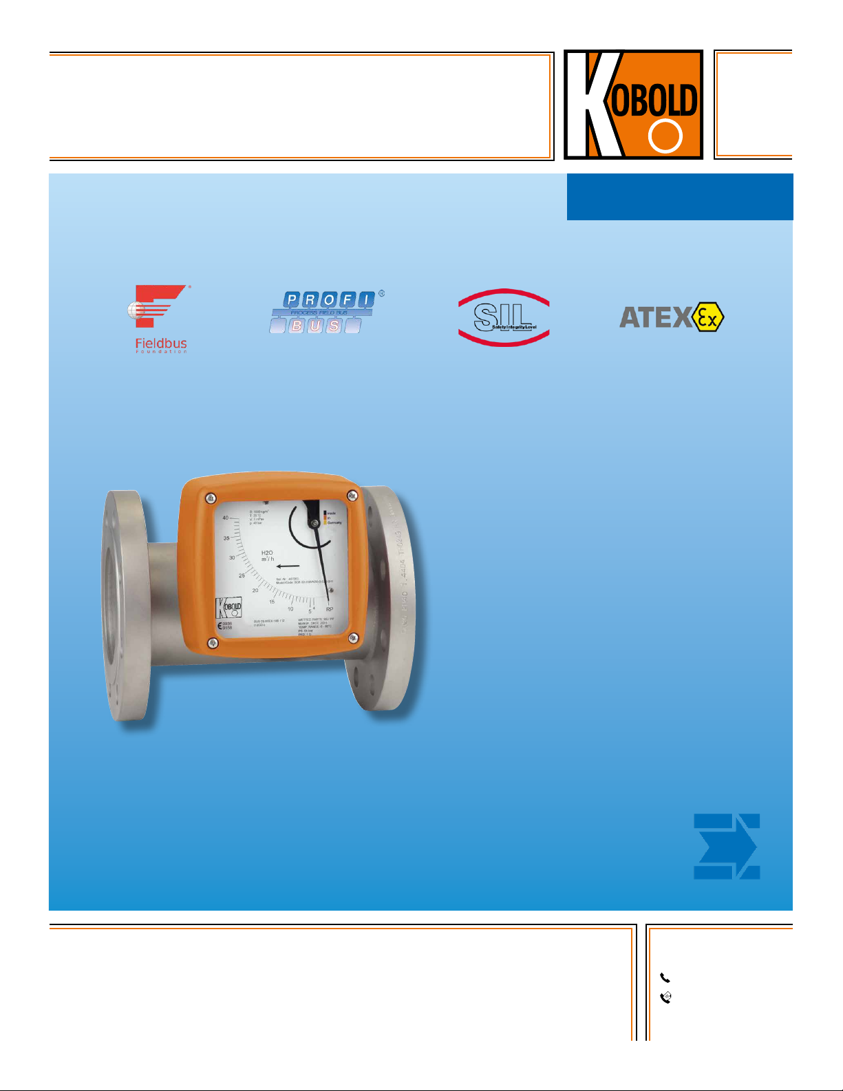
All-Metal Armored Variable Area
Flowmeter and Totalizer
for Horizontal or Vertical Mounting
measuring
•
monitoring
•
analyzing
BGF
●● Measuring Range:
0.044...0.44 to 26.4...264 (Water)
0.176...1.76 to 100...1000 SCFM (Air)
●● Accuracy: ± 2% of Full Scale
●● p
: 580 PSIG
max
(Option: up to 5,800 PSIG)
●● t
: -40 ... 390 °F
max
●● Connection: 1/2" ... 3" ANSI,
1/4"...2" NPT
●● Material: 316L /316-Ti Stainless
Steel, PTFE
●● Options:
Contacts, Analog Output with
HART®, Profibus®-PA, Foundation™
Fieldbus®, Totalizer Module
KOBOLD companies worldwide:
ARGENTINA, AUSTRALIA, AUSTRIA, BELGIUM, BULGARIA, CANADA, CHILE, CHINA, COLOMBIA,
CZECH REPUBLIC, EGYPT, FRANCE, GERMANY, HUNGARY, INDIA, INDONESIA, ITALY, MALAYSIA,
MEXICO, NETHERLANDS, PERU, POLAND, REPUBLIC OF KOREA, ROMANIA, SINGAPORE, SPAIN,
SWITZERLAND, TAIWAN, THAILAND, TUNISIA, TURKEY, UNITED KINGDOM, USA, VIETNAM
01/03-18-2019
KOBOLD Instruments, Inc.
1801 Parkway View Drive
Pittsburgh, PA 15205
Main Ofce:
1.800.998.1020
1.412.788.4890
info@koboldusa.com
www.koboldusa.com
Page 2
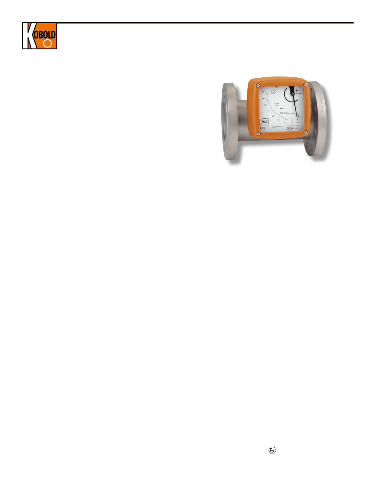
All-Metal Armored Variable Area Flowmeter and Totalizer Model BGF
Description
The KOBOLD BGF metal-armored variable area flowmeter is ideal
for difficult applications requiring high pressure, high temperature
operation or low pressure loss. Its all-metal, armored design
is available in stainless steel or PTFE-clad stainless steel. This
flowmeter is unique in that its design employs a guided float and
spring return mechanism that allows the BGF to be installed into
both horizontal and vertical pipes. In standard configuration,
the flowmeter is a purely mechanical meter suited for water and
compressed gases in line sizes up to 3 inches. Electronic limit
switches and/or an analog flow transmitter may be added if
desired. Analog output is supplied standard with HART® protocol.
Profibus-PA® is also available as an option. Available switches
and analog outputs include those that operate via intrinsically
safe methods of protection and may be used in hazardous areas
where intrinsically safe installations are permitted. Foundation
Fieldbus® is also available as an option. Custom designs for
high pressure operation, special fittings and special materials of
construction are available upon request.
Special Advantages
●● Ideal for Difficult Operating Conditions
●● Can be Used for All Directions of Flow
●● A Large Spectrum of Wetted Materials
●● Magneto-resistive Signal Transmission
●● Special Design for High Pressure
and High Temperature Applications
Technical Details
Sensor
Wetted Materials
SS Meas. Body: 316 L / 316-Ti Stainless Steel,
316-Ti Spring
PTFE Meas. Body: Hastelloy C-22®, PTFE,
Special Materials on Request
Process Connection: ASME B16.5, NPT,
Other Connections on Request
Nominal Pressure: 580 PSIG, ASME Cl150 / 300
(Standard) (BGF-S)
230 PSIG, ASME Cl150
(Standard) (BGF-P)
Higher Pressures Upon Request
(Max. 5800 PSIG)
Process Temperature: -40...300 °F
(BGF-S with Electrical Output)
-40...390 °F
(BGF-S without Electrical Output)
-40...390 °F
(BGF-S with Option V / H / W)
-40...257 °F (BGF-P)
Ambient Temperature: -40...176 °F
Accuracy
Liquid/Gas: ± 2 % of Full Scale
Additional Inaccuracy
by Transmitter (ES): ± 0.2 %
Repeatability: ± 0.8 % of Full Scale
2
www.koboldusa.com
Protection: IP 65 (Aluminum Housing)
IP 67 (Stainless Steel Housing)
Certificate and Accreditation
Explosion Protection: BVS 03 ATEX H/B 112
Display
Material: Aluminum (Stove-Enameled)
Stainless Steel (as Option)
Electrical Outputs: Inductive Switch (Standard),
Inductive Switch (Safety Design),
Microswitch, Others on Request
Ambient Temperature: -40...176 °F (without Switch)
-40...150 °F (with Switch)
Transmitter
●• ES with HART
●• ES with HART
®
Protocol
®
Protocol and
2 NAMUR Switches
●• ES with HART
®
Protocol and
1 NAMUR Switch / 1 Pulse Output
●• ES with Profibus-PA
●• ES with HART
●• ES with Foundation Fieldbus
®
®
Protocol and Totalizer Module
®
Power Supply: 14 - 30 V
DC
Output: Passive, Galvanically Isolated
Current: 4-20 mA
Binary 1 and 2: Ui =30 V, Ii =20 mA, Pi = 100 mW
Input Binary: Counter Reset
(only for ES with Totalizer Module)
Ambient Temperature: -40...158 °F
Certification and Accreditation
Explosion Protection: DMT 00 ATEX E 075
Type of Protection: II 2G EEx ia IIC T6
No responsibility taken for errors;
subject to change without prior notice.
Page 3
All-Metal Armored Variable Area Flowmeter and Totalizer Model BGF
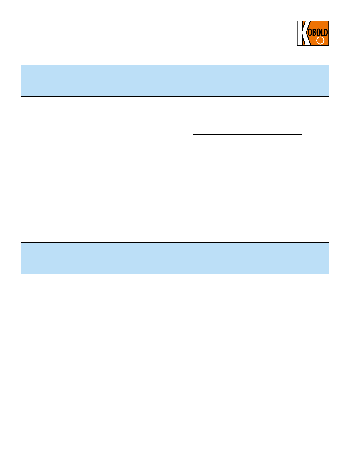
Order Details for DN15 Models: (Example: BGF-S15 201R H KO0 0 S1 0 0K)
DN15 Models
Measuring Ranges: 0.044...0.44 GPM to 0.264...2.64 GPM
Model
Measuring Tube
Material
Connection
Measuring Range*
Code Water Air
Part
Number
Continued
..S15.. = Stainless Steel,
Process Temp.
≤ 390 °F
..201R2).. = 1/2" Class 150 RF ASME
..221R2).. = 1/2" Class 300 RF ASME
..202R.. = 3/4" Class 150 RF ASME
..222R.. = 3/4" Class 300 RF ASME
..H.. 0.044..0.44 GPM 0.176...1.76 SCFM
..I.. 0.071...0.71 GPM 0.294...2.71 SCFM
..203R.. = 1" Class 150 RF ASME
..P15.. = Stainless Steel
BGF-..
Measuring Tube,
PTFE-Lining,
Process Temp.
≤ 257 °F,
Max. Pressure
230 PSIG
*Reference Conditions: Water at 68 °F @1 mPas, Air at 68 °F @ 0 PSIG (Range Values for Other Media Upon Request)
1)
NPT floats can not be removed
2)
Not for BGF-P PTFE Models
..223R.. = 1" Class 300 RF ASME
..204R2).. = 1-1/4" Class 150 RF ASME
..224R2).. = 1-1/4" Class 300 RF ASME
1)2)
..6010
.. = 1/4" NPT
1)2)
..6020
.. = 3/8" NPT
1)2)
..6030
.. = 1/2" NPT
1)2)
..6040
.. = 3/4" NPT
..J.. 0.11...1.1 GPM 0.412...4.12 SCFM
..K.. 0.176...1.76 GPM 0.589...5.88 SCFM
..L.. 0.264...2.64 GPM 1.0...10.0 SCFM
Order Details for DN25 Models: (Example: BGF-S25 202R M KO0 0 S1 0 0K)
DN25 Models
Measuring Ranges: 0.44...4.4 GPM to 1.76...17.6 GPM
Model
Measuring Tube
Material
Connection
Code Water Air
Measuring Range*
To
complete
part
number,
please go
directly to
order table
on page 6.
Part
Number
Continued
..202R3).. = 3/4" Class 150 RF ASME
..M.. 0.44...4.4 GPM 1.76...17.6 SCFM
..222R3).. = 3/4" Class 300 RF ASME
..S25.. = Stainless Steel,
Process Temp.
≤ 390 °F
..P25.. = Stainless Steel
BGF-..
Measuring Tube,
PTFE-Lining,
Process Temp.
≤ 257 °F,
Max. Pressure
230 PSIG
*Reference Conditions: Water at 68 °F @1 mPas, Air at 68 °F @ 0 PSIG (Range Values for Other Media Upon Request)
1)
NPT floats can not be removed
2)
Range not available for BGF-P (PTFE Casing), for BGF-S Only
3)
Not Available for BGF-P with PTFE Casing
No responsibility taken for errors;
subject to change without prior notice.
..203R.. = 1" Class 150 RF ASME
..223R.. = 1" Class 300 RF ASME
..204R3).. = 1-1/4" Class 150 RF ASME
..224R3).. = 1-1/4" Class 300 RF ASME
..205R3).. = 1-1/2" Class 150 RF ASME
..225R3).. = 1-1/2" Class 300 RF ASME
1)3)
..6010
.. = 1/4" NPT
1)3)
..6020
.. = 3/8" NPT
1)3)
..6030
.. = 1/2" NPT
1)3)
..6040
.. = 3/4" NPT
www.koboldusa.com
..N.. 0.705...7.05 GPM 2.35...27.1 SCFM
..P.. 1.1...11 GPM 4.12...41.2 SCFM
..Q 2).. 1.76...17.6 GPM 6.47...64.7 SCFM
To
complete
part
number,
please go
directly to
order table
on page 6.
3
Page 4

All-Metal Armored Variable Area Flowmeter and Totalizer Model BGF
Order Details for DN40 Models: (Example: BGF-S40 205R P KO0 0 S1 0 0K)
DN40 Models
Measuring Ranges: 1.1...11 GPM to 4.4...44 GPM
Model
BGF-..
Measuring Tube
Material
..S40.. = Stainless Steel,
Process Temp.
≤ 390 °F
Connection
..205R.. = 1-1/2" Class 150 RF ASME
..225R.. = 1-1/2" Class 300 RF ASME
..60401).. = 3/4" NPT
..60501).. = 1" NPT
..60601).. = 1-1/4" NPT
Measuring Range*
Code Water Air
..P.. 1.1...11 GPM 4.12...41.2 SCFM
..Q.. 1.76...17.6 GPM 6.47...64.7 SCFM
..R.. 2.64...26.4 GPM 10...100 SCFM
Part
Number
Continued
To
complete
part
number,
please go
directly to
order table
on page 6.
..S.. 4.4...44 GPM 17.0...170 SCFM
*Reference Conditions: Water at 68 °F @1 mPas, Air at 68 °F @ 0 PSIG (Range Values for Other Media Upon Request)
1)
NPT floats can not be removed
Order Details for DN50 Models: (Example: BGF-S50 206R Q KO0 0 S1 0 0K)
DN50 Models
Measuring Ranges: 1.76...17.6 GPM to 11...110 GPM
Model
BGF-..
Measuring Tube
Material
..S50.. = Stainless Steel,
Process Temp.
≤ 390 °F
..P50.. = Stainless Steel
Measuring Tube,
PTFE-Lining,
Process Temp.
≤ 257 °F,
Max. Pressure
230 PSIG
Connection
..206R.. = 2" Class 150 RF ASME
..226R.. = 2" Class 300 RF ASME
..207R2).. = 2-1/2" Class 150 RF ASME
..227R2).. = 2-1/2" Class 300 RF ASME
1)2)
..6060
..6070
..6080
.. = 1-1/4" NPT
1)2)
.. = 1-1/2" NPT
1)2)
.. = 2" NPT
Code Water Air
..Q.. 1.76...17.6 GPM 6.47...64.7 SCFM
..R.. 2.64...26.4 GPM 10...100 SCFM
..S.. 4.4...44 GPM 17.0...170 SCFM
..T.. 7.0...70 GPM 27.0...270 SCFM
..U.. 11...110 GPM 41...410 SCFM
Measuring Range*
Part
Number
Continued
To
complete
part
number,
please go
directly to
order table
on page 6.
*Reference Conditions: Water at 68 °F @1 mPas, Air at 68 °F @ 0 PSIG (Range Values for Other Media Upon Request)
1)
NPT floats can not be removed
2)
Not Available for BGF-P with PTFE Casing
4
www.koboldusa.com
No responsibility taken for errors;
subject to change without prior notice.
Page 5

All-Metal Armored Variable Area Flowmeter and Totalizer Model BGF
Order Details for DN80 Models: (Example: BGF-S80 208R T KO0 0 S1 0 0K)
DN80 Models
Measuring Ranges: 7.05...70.5 GPM to 26.42...264.2 GPM
Model
BGF-..
Measuring Tube
Material
..S80.. = Stainless Steel,
Process Temp.
≤ 390 °F
..P80.. = Stainless Steel
Measuring Tube,
PTFE-Lining,
Process Temp.
≤ 257 °F,
Max. Pressure
230 PSIG
Connection
..208R.. = 3" Class 150 RF ASME
..228R.. = 3" Class 300 RF ASME
Code Water Air
Measuring Range*
..T.. 7.0...70 GPM 27.0...270 SCFM
..U.. 11...110 GPM 41...410 SCFM
..V.. 17.6...176 GPM 64.7...647 SCFM
Part
Number
Continued
To
complete
part
number,
please go
directly to
order table
on page 6.
..W.. 26.4...264.2 GPM 100...1000 SCFM
*Reference Conditions: Water at 68 °F @1 mPas, Air at 68 °F @ 0 PSIG (Range Values for Other Media Upon Request)
No responsibility taken for errors;
subject to change without prior notice.
www.koboldusa.com
5
Page 6

All-Metal Armored Variable Area Flowmeter and Totalizer Model BGF
Continuation of Order Details (Example: BGF-S80 208R T K O 0 0 S 1 0 0K)
Magnet Bearer
..K.. = PP1)
(to
176 °F,
from
DN 50)
..P.. = PTFE
(BGF-S
to
300 °F)
(BGF-P
to
257 °F)
..S.. = St.
Steel
1)
Flow
Direction
..O.. = Top to
Bottom
..L.. = Left
to Right
..R.. = Right
to Left
..U.. = Bottom
to Top
Heating1) /
Cooling
..0.. = without
..1.. = with
Heating,
Ermeto
12 mm
..3.. = with
Heating,
ANSIFlange
½" Class
150
..4.. = with
Heating,
1/2" NPT
Certificates Display Scale
..S.. = Aluminum
..0.. = without
Certificate
..V.. = Aluminum,
Assembled at
..1.. = Certificate of
Compliance
Distance up
to 390 °F
with the Order
2.1
..2.. = Certificate of
Compliance
with the Order
2.2
..B.. = Inspection
Certificate
with Material
Certificate 3.1
..C.. = Inspection
Certificate
with Material
Certificate 3.2
..E.. = St. Steel
..H.. = St. Steel,
Assembled at
Distance up
to 390°F
..T..= Aluminum
with Pressure
Comp.
..W.. = Aluminum
with Pressure
Comp.,
Assembled
at Distance
up to 390 °F
Water
..1.. = %-Scale
..2.. = Measuring
Range
Media
..4.. = %-Scale
..5.. = Measuring
Range
..F2).. = Dual
Scale
**Please Specify
Media Data (See
Below)
Electrical
Output
..0.. = without
..1.. = 1 Inductive
Switch
..2.. = 2 Inductive
Switches
..C.. = 1 × Microswitch
..D.. = 2× Microswitches
..6.. = Transmitter ES
with HART®,
EEx ia, 4-20 mA,
SIL
..7.. = Transmitter ES
with HART®,
EEx ia, 4-20 mA
and 2 NAMURSwitches, SIL
..8.. = Transmitter ES
with HART®, EEx
ia, 4-20 mA, 1
NAMUR Switch
and 1 Pulse
Output
..9.. = Electrical
Transmitter ES
with Profibus®PA, EEx ia
..I.. = 4-20 mA with
HART® Totalizer
Module
..K.. = Electrical
Transmitters
ES with
Foundation™
®
Fieldbus
Accessories
..0K = without
..XK = Special
(Please
Spec.)
1)
Not for model BGF-P (PTFE-coating)
2)
Please specify ranges with units of measurement
*Additional Information Required for Order:
To ensure proper operation, this product requires a completed application guide form to be submitted with any order. Please refer to the
‘documentation’ tab on the bottom of the product page for this product on our website in order to obtain the correct form. You can also contact
your KOBOLD representative for this form.
6
www.koboldusa.com
No responsibility taken for errors;
subject to change without prior notice.
Page 7

Dimensions
A
A
155
1
5
5
2
5
0
A
A
1
9
6
2
5
0
Ø
All-Metal Armored Variable Area Flowmeter and Totalizer Model BGF
Aluminum Display
0
5
2
9.84" (11.81" for NPT Fittings)
Stainless Steel Display
*5.71"
145*
2.76"
70
3
5
1
6.02"
5
5
1
6.10"
0
5
2
,4
7
4
1.87"
9.84" (11.81" for NPT Fittings)
6.10"
155
Øl.W.
*6.22"
158*
3.19"
81
6
0
9
5
1
2
Ø
Ø 7.72"
9.84" (11.81" for NPT Fittings)
Size ANSI I. W. (Inner Width)
1/2" 150/300 1.02" 2.91" 3.94"
1" 150/300 1.26" 3.03" 4.06"
1-1/2" 150/300 1.81" 3.35" 4.33"
2" 150/300 2.76" 3.86" 4.84"
3" 150/300 4.02" 4.49" 5.51"
Dimensional Deviations:
* + 3.94" with forward advanced display
3
5
1
6.02"
0
5
2
8
6
2.68"
9.84" (11.81" for NPT Fittings)
Øl.W.
A
Aluminum Display Stainless Steel Display
No responsibility taken for errors;
subject to change without prior notice.
www.koboldusa.com
7
 Loading...